EP4012152A1 - Procédé de fixation d'un rail de roulement de store et rail de roulement de store fixé par encliquetage au store roulant associé à une fenêtre - Google Patents
Procédé de fixation d'un rail de roulement de store et rail de roulement de store fixé par encliquetage au store roulant associé à une fenêtre Download PDFInfo
- Publication number
- EP4012152A1 EP4012152A1 EP21213054.6A EP21213054A EP4012152A1 EP 4012152 A1 EP4012152 A1 EP 4012152A1 EP 21213054 A EP21213054 A EP 21213054A EP 4012152 A1 EP4012152 A1 EP 4012152A1
- Authority
- EP
- European Patent Office
- Prior art keywords
- roller shutter
- fitting
- rail
- locking
- fastening
- Prior art date
- Legal status (The legal status is an assumption and is not a legal conclusion. Google has not performed a legal analysis and makes no representation as to the accuracy of the status listed.)
- Granted
Links
Images


Classifications
-
- E—FIXED CONSTRUCTIONS
- E06—DOORS, WINDOWS, SHUTTERS, OR ROLLER BLINDS IN GENERAL; LADDERS
- E06B—FIXED OR MOVABLE CLOSURES FOR OPENINGS IN BUILDINGS, VEHICLES, FENCES OR LIKE ENCLOSURES IN GENERAL, e.g. DOORS, WINDOWS, BLINDS, GATES
- E06B9/00—Screening or protective devices for wall or similar openings, with or without operating or securing mechanisms; Closures of similar construction
- E06B9/02—Shutters, movable grilles, or other safety closing devices, e.g. against burglary
- E06B9/08—Roll-type closures
- E06B9/11—Roller shutters
- E06B9/17—Parts or details of roller shutters, e.g. suspension devices, shutter boxes, wicket doors, ventilation openings
- E06B9/17061—Connection of the box to the guides
-
- E—FIXED CONSTRUCTIONS
- E06—DOORS, WINDOWS, SHUTTERS, OR ROLLER BLINDS IN GENERAL; LADDERS
- E06B—FIXED OR MOVABLE CLOSURES FOR OPENINGS IN BUILDINGS, VEHICLES, FENCES OR LIKE ENCLOSURES IN GENERAL, e.g. DOORS, WINDOWS, BLINDS, GATES
- E06B9/00—Screening or protective devices for wall or similar openings, with or without operating or securing mechanisms; Closures of similar construction
- E06B9/56—Operating, guiding or securing devices or arrangements for roll-type closures; Spring drums; Tape drums; Counterweighting arrangements therefor
- E06B9/58—Guiding devices
Definitions
- the invention relates to a method for fastening a roller shutter rail relative to a roller shutter box and a window or door frame, the roller shutter rail for a first bracket, which can be displaced in the direction of a longitudinal extension of the roller shutter rail to accommodate a change in length, having a fixed part of the building Carrier, preferably a window frame, is locked.
- the invention relates to a roller shutter track rail which is positively fastened to a window with a window frame and associated with a roller shutter box by means of a form-fit projection and a form-fit receptacle, with a first form-fit fastening on the window frame causing a movement due to a change in length of the roller shutter track relative to the window frame in a longitudinal direction the roller shutter rail allows.
- roller shutter rails are already known in various configurations.
- the roller shutter running rail known from this has a chamber which is open on one side in cross-section to a contact surface on a window frame and has locking walls protruding on the open chamber wall.
- the roller shutter rail can be latched to a cap screw usually introduced in the window frame for positive connection by means of the latching walls in the rear grip.
- Such positive connections is also on the US 4,234,033A and the DE 298 15 381 U1 to refer.
- roller shutter rails are known, in which an inlet part of the roller shutter box can engage in order to align the rail relative to the roller shutter box.
- a combination of an inlet part of a roller shutter box with a roller shutter rail is also from the DE 20 2017 006 165 U1 known.
- the inlet part here has an insertion tongue with a latching element.
- a mechanically fixed connection is formed between the roller shutter rail in the direction of a longitudinal axis of the roller shutter rail.
- Such a design is also from FR 2 804 156 A1 known for a displaceability of the roller shutter rail in a depth direction of the roller shutter box.
- roller shutter rails are first installed when a window is installed, but then they often have to be dismantled again with a view to plastering and/or painting work later and then reinstalled.
- positive locking on the inlet part can be an obstacle here.
- Merely latching on the frame part of the window, as is often the standard afterwards, can lead to the run-in rail slipping down over time and thus to rolling problems with regard to the roller shutter armor at the transition from the run-in part to the roller shutter rail.
- the invention deals with the task of a method for fastening a roller shutter track relative to a roller shutter box and a window or door frame and also a roller shutter track that is positively fastened to a window with a window frame and assigned to a roller shutter box, which as a method enables advantageous assembly and with regard to the roller shutter track represents a form-locking fastening that has been tried and tested allows the change in length of the roller shutter track.
- this object is initially and essentially achieved with the subject matter of claim 1, whereby it is based on the fact that the roller shutter rail is also reversibly connected to the roller shutter box or the window frame in a form-fitting manner to prevent displacement of the roller shutter rail in the direction of the longitudinal extension .
- the roller shutter track is connected twice in a form-fitting manner, for example latched, with one of the form-fitting connections prevents a shift of the roller shutter rail in the direction of its longitudinal extent, the roller shutter rail can initially be easily installed and also removed again.
- Simple removal is often essential during the construction of a building because, as already mentioned, the roller shutter box with the roller shutter tracks is usually installed before the building has been plastered and, in order to prevent plastering, before removed again after plastering.
- the method according to the invention now enables a two-fold positive connection, which on the one hand enables simple (re) removal and (re) installation, but on the other hand nevertheless, due to the second positive connection to prevent displacement of the roller shutter track in the direction of its longitudinal extent, is prevented that the possible linear expansion, which is compensated for by the first form-fitting fastening, can lead to the roller shutter rail moving downwards over time, resulting in a gap in relation to the roller shutter box, which impedes free movement of a roller shutter of the roller shutter.
- the respective form-fitting connection can be a latching connection, for example, further formed, for example, by a latching projection which interacts with a latching recess.
- the objective design of the positively connected, for example latched, roller shutter running rail ensures that the form-fitting fastening can be easily detached and restored.
- the positive-locking openings can have a longitudinal extension directed transversely to one another.
- the form-fitting opening of the second form-fitting attachment can be limited in size only to the form-fitting projection.
- the procedure described and the embodiment described is further preferably designed such that manual intervention in a running opening of the roller shutter rail and pulling on the roller shutter rail removes the roller shutter rail both from the form-fitting connection with the carrier and from the form-fitting connection with the roller shutter box is solvable.
- the double positive connection can be made during installation by simply pressing in the direction of the carrier or in the direction of the roller shutter box.
- the form-fitting connection with the roller shutter box can be carried out first and then the form-fitting connection with the window frame.
- the design preferably also allows the form-fitting connection to be made with the window frame first and then, for example by pushing it up a certain way, the form-fitting connection to the roller shutter box.
- the form-fitting projection and/or the form-fitting receptacle has a pull-out bevel, which also allows the form-fitting connection to be released by a force acting on the roller shutter rail remote from the form-fitting connection.
- a pull-out bevel which also allows the form-fitting connection to be released by a force acting on the roller shutter rail remote from the form-fitting connection.
- the form-locking fastening which can be overridden as it were, thanks to the extraction bevel mentioned above, allows the preferred handling of the roller shutter track when removing or installing without directly affecting the parts of the form-locking fastening, the form-fitting projection or the form-fitting receptacle itself.
- the first form-fitting attachment can be achieved by an engagement of a form-fitting projection in a form-fitting receptacle that is longer in the direction of the longitudinal extension.
- a continuous opening over a length of the roller shutter track is usually and preferably provided. However, it can also be oblong holes.
- the second form-fitting attachment is achieved by engagement of a form-fitting projection in a form-fitting receptacle that is limited in the direction of the longitudinal extent to a dimension of the form-fitting projection.
- the form-fitting receptacle can be an opening in a wall of the roller shutter track when the form-fitting projection is attached to the roller shutter box.
- the form-fitting projection of the second form-fitting attachment is formed on a spring arm.
- a constant load can be achieved in the form-fitting position when the spring arm acts on the form-fitting projection with pretension in the form-fitting position.
- the spring arm is part of a spring clip. This can also advantageously a run-in slope for the spring arm be achieved even with regard to the roller shutter track.
- this spring clip is preferably a closed spring clip.
- the spring arm more preferably the spring clip described, can be formed or attached to a side or bottom part of the roller shutter box.
- the spring arm or the spring clip can also be formed or attached to an inlet part of the roller shutter box.
- the molding more preferably means that the spring arm or the spring clip is produced integrally and uniformly with the inlet part using the plastic injection molding process.
- the form-fitting projection is formed on the roller shutter track and the form-fitting receptacle on the roller shutter box, it is also preferable for the form-fitting projection to be connected to the roller shutter track via a spring, optionally a spring clip.
- the spring arm or the spring clip can be screwed to the roller shutter box or the roller shutter track or, in turn, can be latched again, for example.
- latching a non-detachable latching connection between the spring arm or the spring clip and the roller shutter track is preferred.
- the spring arm carrying the positive-locking projection or the spring clip can be attached to the window frame as a whole, in order to interact with a positive-locking receptacle of the running rail.
- the form-fit receptacle or the form-fit projection can be attached to a head piece of the roller shutter box.
- the spring arm or the spring clip having the spring arm can basically be provided as a separate part designed for attachment, for example consisting of a metal material or a plastic that may differ from the material of the roller shutter box and/or the running rail and/or the window frame.
- the proposed invention can also be used in so-called aluminum front-mounted boxes, for example during a renovation.
- the roller shutter box is preferably mounted with the slide bar attached.
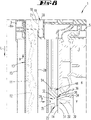
- a roller shutter box 1 for windows and/or doors.
- the roller shutter box 1 sits on a frame 6 .
- a roller shutter rail 13 is attached on the roller shutter box 1 and the frame 6, a roller shutter rail 13 is attached.
- the roller shutter box 1 is preferably made up of extruded plastic and/or injection-moulded plastic parts, more particularly hollow plastic profiles.
- the roller shutter box 1 has a rear wall 2 pointing to the inside of the room RI, a front wall 3 pointing to the outside of the room RA, as well as a ceiling wall 4.
- the front wall 3 and the rear wall 2 protrude perpendicularly from the horizontally aligned ceiling wall 4 in cross-section.
- the roller shutter box 1 can be placed on the frame 6 of the window or door and more preferably can be fastened to it.
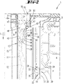
- the figure 1 shows the roller shutter box 1 in the seated and fixed configuration.
- the roller shutter box 1 is closed on both ends of its longitudinal extension by a side part 7 .
- the latter is preferably in the form of a plastic injection molded part.
- the roller shutter box 1 serves to accommodate a roller shutter shaft 8, which carries a roller shutter curtain 9 that can be wound up or unwound—shown only schematically in the drawings.
- the shaft axis x extends in the longitudinal direction of the roller shutter box 1, wherein the rotation of the roller shutter shaft 8 permitting mounting of the same in the area of the side parts 7 also takes place.
- a slot-shaped outlet opening 10 extending over the entire length of the roller shutter box 1 between the side parts 7 is assigned to the transition region of the bottom part 5 into the front wall 3 in the bottom part 5 .
- This serves to allow the roller shutter rods 11 of the roller shutter curtain 9 to exit into a guide groove 12 that is vertically aligned when installed.
- the latter is formed in the roller shutter guide rail 13, which is preferably formed as a plastic extrusion part.
- the roller shutter track 13 is preferably aligned in such a way that its inwardly pointing edge 14 is on the facing outer surface 31 of the frame 6 is supported.
- the edge surface 15 of the roller shutter runner 13 pointing outwards can essentially run in the vertical plane formed by the outer surface of the front wall 3 .
- the face of the roller shutter rail 13 pointing vertically upwards can come into contact with the facing lower surface of the associated side part 7 or base part 5 in the arrangement and use position, so that the roller shutter slats 11 can enter the guide groove 12 unhindered.
- the guide groove 12 also has two flanks which run parallel to one another and are aligned vertically when the roller shutter track 13 is installed, preferably an inner flank 16 on the frame side and an outer front flank 17.
- an inlet part 19 can be provided in the roller shutter box 1, each associated with a side part 7.
- Each inlet part 19 forms an inlet shoulder 20 pointing vertically upwards into the interior of the box, for guiding the roller shutter slats 11 sliding off the roller shutter shaft 8 into the guide groove 12 of the roller shutter guide rail 13.
- the effective, vertically aligned surface 21 of the inlet shoulder 20 or of the inlet part 19 preferably runs essentially in a vertical plane formed by the flank 16 of the guide groove 12 on the frame side.
- the inlet part 19 or the inlet shoulder 20 is preferably formed in one piece, made of the same material as the side part 7 , but in an alternative embodiment it can also be formed as an individual part that can be plugged into the side part 7 .
- roller shutter track 13 in the installed state shown, for example, figure 1 a longitudinal extension L in the vertical direction.
- roller shutter rail 13 is preferably fixed to the frame 6 via a first form-fitting fastening 22, preferably in the form of a snap-in fastening, with this form-fitting fastening 22 causing a movement of the roller shutter running rail 13 relative to the frame 6 in the longitudinal extension L of the running rail a change in length of the same, for example due to heat radiation, allowed.
- the roller shutter running rail 13 has a positive-locking receptacle 23, for example a snap-in receptacle, which opens toward the inwardly pointing edge 14, which is more preferably formed over the entire extent of the running rail in the longitudinal extent L when the roller shutter running rail 13 is designed as a plastic extrusion .
- a positive-locking receptacle 23 for example a snap-in receptacle, which opens toward the inwardly pointing edge 14, which is more preferably formed over the entire extent of the running rail in the longitudinal extent L when the roller shutter running rail 13 is designed as a plastic extrusion .
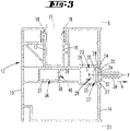
- the positive-locking receptacle 23 extends essentially in the plane of the edge 14 - with reference to the usual position of use - i.e. a vertically oriented plane in which the receiving opening 24 is also formed, with receiving flanks on both sides of the receiving flanks preferably running parallel to one another in the cross section according to Figure 3 25, 26 outgoing and facing each other, the slit-shaped receiving opening 24 delimiting Locking webs 27, 28, which can also be referred to as locking walls provided.
- a positive-locking projection 29 fixed on the frame side for example a latching projection, further for example, as is also preferred, in the form of a head or nipple screw provided with a preferably self-tapping thread 30 .
- a plurality of such form-fitting projections 29 are preferably provided over the length of the roller shutter runner 13, corresponding to an imaginary line in the vertical direction on the frame 6.
- Each positive-locking projection 29 can, as is also preferred, sit on the outer surface 31 of the frame 6 facing the roller shutter runner 13 or its edge 14 with a preferably circular-cylindrical support section 32 .
- the section having the thread 30 extends along the central axis y, while opposite the thread 30 there is a form-fitting section 33 which is radially expanded in relation to the support section 32 .
- the form-fitting section 33 is provided with a largest outer diameter, which is selected to be larger than the opening dimension of the receiving opening 24 viewed transversely to the longitudinal extent L, so that in the locked form-fitting position according to FIG figure 3 the form-fitting section 33 rests in the groove-like form-fitting receptacle 23 and catches behind the locking webs 27, 28 in a locking manner.
- the form-fitting section 33 is provided with both a push-on direction (see arrow a in figure 3 ) of the roller shutter running rail 13 acting on the form-fitting projection 29 insertion bevel 35 and with a counter extraction bevel 34 acting in this attachment direction a, and to enable the elastically resilient opening area between the locking webs 27 and 28 to be snapped on or released without the use of tools.
- a second form-fit fastening 36 is also provided, which in a preferred embodiment the roller shutter -Run rail 13 holds in its face contact position on the facing lower surface of the side part 7.
- this second positive-locking fastening 36 like the first positive-locking fastening 22, can preferably be removed without tools and also, more preferably, can be taken in without tools.
- the design is such that even if the actual form-fitting partners only manually intervene in the running groove, the roller shutter track 13 can be easily detached from both form-fitting connections without there being any direct action by hand or even with Tool on one of the form-fitting partners themselves requires.
- the roller shutter track 13 can, for example, as well as preferred and based on the Figures 1 to 5 illustrated embodiment, in the region of a chamber 37 formed adjacent to but separate from the guide groove 12 preferably have bore-like form-fit receptacles 38 .
- This can, as is also preferred, be formed in a chamber web 39 running essentially parallel to a flank 16 or 17 of the guide groove 12, more preferably in a chamber web 39 facing the inner peripheral edge 14.
- the form-fitting receptacle 38 which acts as a snap-in receptacle, is more preferably provided in the upper end region of the roller shutter track 13 facing the side part 7 in the normal state of use, more preferably in a region in lateral or horizontal overlap with a horizontally running, vertical upper frame part of the window or the door .
- a form-fitting projection 40 connected to the roller shutter box side is provided for form-fitting interaction with the above-described form-fitting receptacle 38 of the second form-fitting attachment 36 .
- This can, as further preferred, be a locking projection protruding in the manner of a pin or a cap relative to a base, more preferably with a cross-sectional geometry which is essentially adapted to the opening geometry of the positive-locking receptacle 38, so that in the resulting Locking form-fitting position preferably no or possibly only the proper function in the interaction of the roller shutter running rail 13 and the roller shutter curtain 9 running into the guide groove 12 further ensures that there is little play.
- the positive-locking projection 40 is also provided, in particular, with a pull-out bevel 51 which interacts with the edge of the bore-like positive-locking receptacle 38 in the course of a release of the second positive-locking fastening 36 .
- a pull-out bevel 51 which interacts with the edge of the bore-like positive-locking receptacle 38 in the course of a release of the second positive-locking fastening 36 .
- the pull-out slope 51 can also form a pull-in slope in the course of assuming the form-fitting position.
- the positive-locking projection 40 is preferably formed on a spring arm 41, more preferably formed in one piece with it and made of the same material.
- This spring arm 41 dips into the chamber 37 of the roller shutter track 13 for latching, so that the form-locking projection 40 deflecting outwards from the spring arm 41 can spring into the form-locking receptacle 38 .
- the spring arm 41 loads the form-fitting projection 40 in the direction of the locking form-fitting position, with the form-fitting projection 40 preferably initially sliding along the inside of the chamber web 39 during the course of immersion into the chamber 39, with the spring arm 41 correspondingly yielding in a resilient manner the form-fitting projection 40 automatically fits into the form-fitting receptacle 38 (compare the dash-dotted representation in figure 2 ).
- the spring arm 41 can also be part of a spring clip 42 .
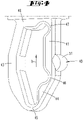
- this can be designed overall in the form of an O-ring, preferably with a rigid support bracket 43 running in the shape of a circular arc segment, to which an overall resilient area extends, mirrored about a vertical plane with reference to the usual position of use. which area is preferably connected to the support bracket 43 in one piece and of the same material at the end.
- the spring clip 42 designed in this way can be designed as a plastic injection-molded part.
- the springy area opposite the support bracket 43 is essentially made up of two sections, preferably of the above-described spring arm 41 with the form-fitting projection 40 formed thereon and an articulated arm 44 that can be pivoted to a limited extent relative thereto Joint section 45 is connected to the carrying bracket 43 and at the other end to the spring arm 41 via a further joint section 46.
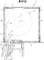
- the spring arm 41 is connected via a third joint section 47 to a base section 48 which also holds the carrying bracket 43 (compare in particular the illustration in figure 4 ).
- the extent of the spring clip 42 designed in this way transversely and perpendicularly to the longitudinal extent L of the running rail 13 in the usage position is essentially adapted to the clear extent of the chamber 37.
- the spring clip 42 can be formed in one piece and of the same material with the inlet part 19 and/or with the side part 7 via the base section 48 .
- a preferably non-detachable snap-in mount can alternatively be provided, such as that shown, for example, in figure 2 is shown schematically.
- a resilient locking section 49 which can be fixed in a locking manner in a chamber-like opening 50 , for example in the side part 7 .
- the roller shutter track 13 can be fixed without tools in a manner that is favorable in terms of handling both in the area of the first form-fitting attachment 22 and in the area of the second form-fitting attachment 36 , and can also be released without tools by removing the above-described form-fitting attachments will.
- roller shutter runner 13 For example, to loosen the roller shutter runner 13, it is sufficient to act on it, if necessary in a region of the runner rail 13 that is remote from the second positive-locking fastening 36, for example at the bottom, further, for example, as a result of pivoting and the associated cancellation of the first positive-locking fastening 22 and at the same time or subsequent removal of the roller shutter track 13 essentially vertically downwards against a direction b of the second form-fit fastening 36 directed essentially perpendicularly to the direction a of the first form-fit fastening 22 (cf figure 5 ).
- the respective extraction bevel 34, 51 is acted on via the form-fitting receptacle 23 or 38 in such a way that the corresponding form-fitting projection 29 or 38 is displaced from the form-fitting receptacle into a position that cancels the respective form-fitting position, this in particular with regard to the second form-fitting fastening 36 with the spring arm 41 carrying the form-fitting projection 40 being resiliently moved back.
- the resilient restoring force for aligning in particular the spring arm 41 with its form-fitting projection 40 in the basic position that preferably corresponds to the form-fitting position according to FIG figure 4 can, as further preferred, result from the elastically restorable joint sections 45 and/or 46 and/or 47.
- roller shutter rail 13 can also be attached both to the frame 6 and to the roller shutter box 1, in particular as a result of the vertically upper end of the rail 13 being slipped over the spring clip 42, so that it dips into the chamber 37 and in the course the slip-on movement in slip-on direction b assumes the form-fitting position, while at the same time or finally a slip-on movement transversely thereto in slip-on direction a creates a positive-locking connection between the groove-like form-fit receptacle 23 and the screw heads or form-fitting projections 29.
- the figure 6 shows a second embodiment for forming the second form-fit fastening 36.
- the positive-locking projection 40 is formed on a spring arm 41 of a spring clip 42, as described above with reference to the first exemplary embodiment.
- This spring clip 42 is also designed as a separate part here, but is held in place on the running rail 13 in contrast to the first embodiment.
- the latching sections 49 engage in openings 50 in the region of the chamber 37 on the running rail side.
- the area of the spring arm 41 that carries the form-fitting projection 40 protrudes into the area of the outlet opening 10 of the roller shutter box 1, with the form-fitting projection 40 engaging in a bore-like form-fitting receptacle 38 provided there in a latching manner.
- the spring clip 42 has a plate-like base 52 in the region of its support bracket 43, via which a fastening, for example screw fixing, of the spring clip 42 on the surface of the window frame facing the running rail 13 6 can be provided.
- a fastening for example screw fixing
- the spring arm 41 protrudes into the area of the form-fit receptacle 23 of the first form-fit fastening 22 .
- a bore-like positive-locking receptacle 38 is provided for latching interaction with the positive-locking projection 40 of the second positive-locking fastening 36 .
- the running rail 13 can be secured against slipping down solely by the spring loading on the receptacle base 53 by the spring clip 42 or by the spring arm 41 .
- the form-fitting projection 40 of the second form-fitting attachment 36 can be formed by a blocking part 54, which is fastened between the receiving flanks 25 and 26 and/or on the receiving base 53 of the groove-like form-fitting receptacle 23, for example is adhesively fastened (cf figure 8 ).
- the blocking part 54 sits on top of the form-fitting projection 29 of the first form-fitting fastening 22 and thus prevents the running rail 13 from slipping off.
- the form-fitting projection 29 of the first form-fitting attachment 22 accordingly forms the form-fitting receptacle 38 of the second form-fitting attachment at the same time.
- roller shutter rail 13 is additionally reversibly connected to the roller shutter box 1 or the window frame 6 in a form-fitting manner to prevent displacement of the roller shutter rail 13 in the direction of the longitudinal extension L.
- a roller shutter track which is characterized in that the roller shutter track 13 is attached to the roller shutter box 1 at the same time with a second positive-locking fastener 36, that the positive-locking projection 40 of the second positive-locking fastener 36 causes a movement by resting against a stop aligned transversely to the longitudinal extent L of the roller shutter rail 13 in the longitudinal direction L and that the form-fitting projections 29, 40 or form-fitting receptacles 23, 38 are designed in such a way that both the first and the second form-fitting fastening 22, 36 release the roller shutter running rail 13 from the first or second form-fitting fastening 22, 36 without affecting a form-fitting projection 29, 40 or a form-fitting receptacle 23, 38 itself.
- a roller shutter track which is characterized in that the form-fitting projection 29, 40 and/or the form-fitting receptacle 23, 38 has a pull-out bevel 34, 51, which also removes the loosening of the form-fitting fastening 22, 36 by a force acting on the roller shutter track 13 to the form-fitting attachment 22, 36 allows.
- a roller shutter track which is characterized in that the first form-fitting connection 22 by an engagement of a form-fitting projection 29 is reached in a form-fit receptacle 23 that is longer in the direction of the longitudinal extension L.
- a roller shutter track which is characterized in that the second form-fitting attachment 36 is achieved by engaging a form-fitting projection 40 in a form-fitting receptacle 38 that is limited in the direction of the longitudinal extension L to a dimension of the form-fitting projection 40 .
- a roller shutter track which is characterized in that the form-fitting projection 40 of the second form-fitting attachment 36 is formed on a spring arm 41.
- a roller shutter track which is characterized in that the spring arm 41 is formed on or attached to a side or bottom part 7, 5 of the roller shutter box 1.
- a roller shutter runner which is characterized in that the spring arm 41 is molded onto or attached to the runner 13 .
- a roller shutter track characterized in that the spring arm 41 is attached to the window frame 6.
- a roller shutter track which is characterized in that the spring arm 41 is molded onto or attached to an inlet part 19 of the roller shutter box 1 .
- a roller shutter track which is characterized in that the spring arm 41 is part of a spring clip 42.
- roller shutter box 29 form-fitting projection 2 back panel 30 thread 3 front wall 31 outer surface 4 ceiling wall 32 support section 5 bottom part 33 form fit section 6 frame 34 draft 7 side part 35 draft 8th shutter shaft 36 second 9 shutter armor Form-fit fastening 10 exhaust port 37 chamber 11 roller shutter rod 38 Form-fit recording 12 guide groove 39 chamber bar 13 Roller shutter track 40 form-fitting projection 14 border edge 41 spring arm 15 border edge 42 spring clip 16 flank 43 carrying handle 17 flank 44 articulated arm 18 seal brush 45 joint section 19 inlet part 46 joint section 20 entry shoulder 47 joint section 21 Surface 48 base section 22 first form-fit fastening 49 rest section 23 Form-fit recording 50 opening 24 receiving opening 51 draft 25 recording edge 52 Base 26 recording edge 53 recording floor 27 rest bar 54 blocking part 28 rest bar a mounting direction b mounting direction x shaft axis y central axis L longitudinal extent RI room inside RA room exterior
Landscapes
- Engineering & Computer Science (AREA)
- Structural Engineering (AREA)
- Architecture (AREA)
- Civil Engineering (AREA)
- Operating, Guiding And Securing Of Roll- Type Closing Members (AREA)
Applications Claiming Priority (2)
| Application Number | Priority Date | Filing Date | Title |
|---|---|---|---|
| DE102020132747 | 2020-12-09 | ||
| DE102021116832.5A DE102021116832A1 (de) | 2020-12-09 | 2021-06-30 | Verfahren zum Befestigen einer Rollladen-Laufschiene und an einem Fenster zugeordnet einem Rollladenkasten rastbefestigte Rollladen-Laufschiene |
Publications (2)
| Publication Number | Publication Date |
|---|---|
| EP4012152A1 true EP4012152A1 (fr) | 2022-06-15 |
| EP4012152B1 EP4012152B1 (fr) | 2023-05-03 |
Family
ID=78824720
Family Applications (1)
| Application Number | Title | Priority Date | Filing Date |
|---|---|---|---|
| EP21213054.6A Active EP4012152B1 (fr) | 2020-12-09 | 2021-12-08 | Procédé de fixation d'un rail de roulement de store et rail de roulement de store fixé par encliquetage au store roulant associé à une fenêtre |
Country Status (2)
| Country | Link |
|---|---|
| EP (1) | EP4012152B1 (fr) |
| PL (1) | PL4012152T3 (fr) |
Citations (9)
| Publication number | Priority date | Publication date | Assignee | Title |
|---|---|---|---|---|
| US4234033A (en) | 1978-03-08 | 1980-11-18 | Firmaframe Nominees Proprietary Limited | Roller door and frame combination |
| DE4445303C1 (de) * | 1994-12-19 | 1996-01-11 | Warema Renkhoff Gmbh & Co Kg | Sonnenschutzanlage |
| DE29815381U1 (de) | 1998-08-27 | 1999-02-25 | Friedrich, Hans, 56566 Neuwied | Vorrichtung zur lösbaren Verbindung von Rolladen-Profilführungen mit dem Fenster-Blendrahmen |
| FR2804156A1 (fr) | 2000-01-25 | 2001-07-27 | Deprat Jean Sa | Dispositif de connexion entre un caisson de volet roulant et une glissiere de guidage |
| EP1811120B1 (fr) | 2006-01-19 | 2011-08-10 | Veka AG | Coffre de store destiné au montage sur un dormant |
| FR2998608A1 (fr) * | 2012-11-29 | 2014-05-30 | France Fermetures | Volets roulants |
| DE202010018232U1 (de) | 2010-01-21 | 2014-11-19 | Exte-Extrudertechnik Gmbh | Rollladenkasten |
| EP2952669A1 (fr) * | 2014-06-02 | 2015-12-09 | Roma Kg | Dispositif pare-soleil de bâtiment et rails de guidage latéraux |
| DE202017006165U1 (de) | 2017-11-29 | 2017-12-11 | Alukon Kg | Rollladenkasten mit in Breitenrichtung verstellbarem Führungsprofil |
-
2021
- 2021-12-08 PL PL21213054.6T patent/PL4012152T3/pl unknown
- 2021-12-08 EP EP21213054.6A patent/EP4012152B1/fr active Active
Patent Citations (9)
| Publication number | Priority date | Publication date | Assignee | Title |
|---|---|---|---|---|
| US4234033A (en) | 1978-03-08 | 1980-11-18 | Firmaframe Nominees Proprietary Limited | Roller door and frame combination |
| DE4445303C1 (de) * | 1994-12-19 | 1996-01-11 | Warema Renkhoff Gmbh & Co Kg | Sonnenschutzanlage |
| DE29815381U1 (de) | 1998-08-27 | 1999-02-25 | Friedrich, Hans, 56566 Neuwied | Vorrichtung zur lösbaren Verbindung von Rolladen-Profilführungen mit dem Fenster-Blendrahmen |
| FR2804156A1 (fr) | 2000-01-25 | 2001-07-27 | Deprat Jean Sa | Dispositif de connexion entre un caisson de volet roulant et une glissiere de guidage |
| EP1811120B1 (fr) | 2006-01-19 | 2011-08-10 | Veka AG | Coffre de store destiné au montage sur un dormant |
| DE202010018232U1 (de) | 2010-01-21 | 2014-11-19 | Exte-Extrudertechnik Gmbh | Rollladenkasten |
| FR2998608A1 (fr) * | 2012-11-29 | 2014-05-30 | France Fermetures | Volets roulants |
| EP2952669A1 (fr) * | 2014-06-02 | 2015-12-09 | Roma Kg | Dispositif pare-soleil de bâtiment et rails de guidage latéraux |
| DE202017006165U1 (de) | 2017-11-29 | 2017-12-11 | Alukon Kg | Rollladenkasten mit in Breitenrichtung verstellbarem Führungsprofil |
Also Published As
| Publication number | Publication date |
|---|---|
| EP4012152B1 (fr) | 2023-05-03 |
| PL4012152T3 (pl) | 2023-09-11 |
Similar Documents
| Publication | Publication Date | Title |
|---|---|---|
| WO2017182286A1 (fr) | Système de porte coulissante | |
| WO2004104355A1 (fr) | Element profile servant a former un volet roulant a isolation acoustique | |
| DE102014109429A1 (de) | Beschlag für eine Schiebetür | |
| EP1091081B1 (fr) | Dispositif de guidage pour un volet roulant, un store enroulable ou similaire | |
| EP0352409B1 (fr) | Dispositif porteur d'espacement pour porteurs de lamelle des stores à lamelles verticales | |
| DE4407922C2 (de) | Rolladenanordnung | |
| DE3441444A1 (de) | Glashalteleiste | |
| DE202012000898U1 (de) | Eckverbindungsbeschlag | |
| EP4012152B1 (fr) | Procédé de fixation d'un rail de roulement de store et rail de roulement de store fixé par encliquetage au store roulant associé à une fenêtre | |
| DE102021116832A1 (de) | Verfahren zum Befestigen einer Rollladen-Laufschiene und an einem Fenster zugeordnet einem Rollladenkasten rastbefestigte Rollladen-Laufschiene | |
| DE10122637A1 (de) | Dichtungsanordnung für ein Kraftfahrzeugfenster | |
| DE29508686U1 (de) | Bausatz zum Erstellen von Umkleidekabinen, Trennwänden u.dgl. | |
| DE19513954A1 (de) | Schutzrollo | |
| CH580219A5 (en) | Hollow member for window frame - sealing strips for glass and retaining member fit into channels formed between ribs | |
| AT10391U1 (de) | Insektenschutzvorrichtung | |
| DE102010022078A1 (de) | Jalousie- oder Rolladeneinrichtung | |
| DE10304899A1 (de) | Rollladen | |
| EP1629173B1 (fr) | Element profile servant a former un volet roulant | |
| DE29804797U1 (de) | Fenster oder Tür | |
| EP2453097A2 (fr) | Dispositif de verrouillage pour une porte sectionnelle latérale | |
| DE102008034613A1 (de) | Vorbaurollladen | |
| EP3916191A1 (fr) | Système de fixation d'une unité fonctionnelle d'un dispositif d'ombrage de l'ouverture d'un bâtiment | |
| DE20214713U1 (de) | Rollo, insbesondere Fensterrollo, zum Einbau in ein Kraftfahrzeug | |
| DE2416567A1 (de) | Vorrichtung zur erneuerung von fenstern | |
| DE10050176B4 (de) | Einrastbare Führungsschiene |
Legal Events
| Date | Code | Title | Description |
|---|---|---|---|
| PUAI | Public reference made under article 153(3) epc to a published international application that has entered the european phase |
Free format text: ORIGINAL CODE: 0009012 |
|
| STAA | Information on the status of an ep patent application or granted ep patent |
Free format text: STATUS: THE APPLICATION HAS BEEN PUBLISHED |
|
| AK | Designated contracting states |
Kind code of ref document: A1 Designated state(s): AL AT BE BG CH CY CZ DE DK EE ES FI FR GB GR HR HU IE IS IT LI LT LU LV MC MK MT NL NO PL PT RO RS SE SI SK SM TR |
|
| STAA | Information on the status of an ep patent application or granted ep patent |
Free format text: STATUS: REQUEST FOR EXAMINATION WAS MADE |
|
| 17P | Request for examination filed |
Effective date: 20221014 |
|
| RBV | Designated contracting states (corrected) |
Designated state(s): AL AT BE BG CH CY CZ DE DK EE ES FI FR GB GR HR HU IE IS IT LI LT LU LV MC MK MT NL NO PL PT RO RS SE SI SK SM TR |
|
| GRAP | Despatch of communication of intention to grant a patent |
Free format text: ORIGINAL CODE: EPIDOSNIGR1 |
|
| STAA | Information on the status of an ep patent application or granted ep patent |
Free format text: STATUS: GRANT OF PATENT IS INTENDED |
|
| RIC1 | Information provided on ipc code assigned before grant |
Ipc: E06B 9/58 19900101ALI20230109BHEP Ipc: E06B 9/17 19680901AFI20230109BHEP |
|
| INTG | Intention to grant announced |
Effective date: 20230208 |
|
| GRAS | Grant fee paid |
Free format text: ORIGINAL CODE: EPIDOSNIGR3 |
|
| GRAA | (expected) grant |
Free format text: ORIGINAL CODE: 0009210 |
|
| STAA | Information on the status of an ep patent application or granted ep patent |
Free format text: STATUS: THE PATENT HAS BEEN GRANTED |
|
| AK | Designated contracting states |
Kind code of ref document: B1 Designated state(s): AL AT BE BG CH CY CZ DE DK EE ES FI FR GB GR HR HU IE IS IT LI LT LU LV MC MK MT NL NO PL PT RO RS SE SI SK SM TR |
|
| REG | Reference to a national code |
Ref country code: GB Ref legal event code: FG4D Free format text: NOT ENGLISH |
|
| REG | Reference to a national code |
Ref country code: DE Ref legal event code: R096 Ref document number: 502021000645 Country of ref document: DE |
|
| REG | Reference to a national code |
Ref country code: AT Ref legal event code: REF Ref document number: 1564724 Country of ref document: AT Kind code of ref document: T Effective date: 20230515 Ref country code: CH Ref legal event code: EP |
|
| REG | Reference to a national code |
Ref country code: IE Ref legal event code: FG4D Free format text: LANGUAGE OF EP DOCUMENT: GERMAN |
|
| P01 | Opt-out of the competence of the unified patent court (upc) registered |
Effective date: 20230523 |
|
| REG | Reference to a national code |
Ref country code: LT Ref legal event code: MG9D |
|
| REG | Reference to a national code |
Ref country code: NL Ref legal event code: MP Effective date: 20230503 |
|
| PG25 | Lapsed in a contracting state [announced via postgrant information from national office to epo] |
Ref country code: SE Free format text: LAPSE BECAUSE OF FAILURE TO SUBMIT A TRANSLATION OF THE DESCRIPTION OR TO PAY THE FEE WITHIN THE PRESCRIBED TIME-LIMIT Effective date: 20230503 Ref country code: PT Free format text: LAPSE BECAUSE OF FAILURE TO SUBMIT A TRANSLATION OF THE DESCRIPTION OR TO PAY THE FEE WITHIN THE PRESCRIBED TIME-LIMIT Effective date: 20230904 Ref country code: NO Free format text: LAPSE BECAUSE OF FAILURE TO SUBMIT A TRANSLATION OF THE DESCRIPTION OR TO PAY THE FEE WITHIN THE PRESCRIBED TIME-LIMIT Effective date: 20230803 Ref country code: NL Free format text: LAPSE BECAUSE OF FAILURE TO SUBMIT A TRANSLATION OF THE DESCRIPTION OR TO PAY THE FEE WITHIN THE PRESCRIBED TIME-LIMIT Effective date: 20230503 Ref country code: ES Free format text: LAPSE BECAUSE OF FAILURE TO SUBMIT A TRANSLATION OF THE DESCRIPTION OR TO PAY THE FEE WITHIN THE PRESCRIBED TIME-LIMIT Effective date: 20230503 |
|
| PG25 | Lapsed in a contracting state [announced via postgrant information from national office to epo] |
Ref country code: RS Free format text: LAPSE BECAUSE OF FAILURE TO SUBMIT A TRANSLATION OF THE DESCRIPTION OR TO PAY THE FEE WITHIN THE PRESCRIBED TIME-LIMIT Effective date: 20230503 Ref country code: LV Free format text: LAPSE BECAUSE OF FAILURE TO SUBMIT A TRANSLATION OF THE DESCRIPTION OR TO PAY THE FEE WITHIN THE PRESCRIBED TIME-LIMIT Effective date: 20230503 Ref country code: LT Free format text: LAPSE BECAUSE OF FAILURE TO SUBMIT A TRANSLATION OF THE DESCRIPTION OR TO PAY THE FEE WITHIN THE PRESCRIBED TIME-LIMIT Effective date: 20230503 Ref country code: IS Free format text: LAPSE BECAUSE OF FAILURE TO SUBMIT A TRANSLATION OF THE DESCRIPTION OR TO PAY THE FEE WITHIN THE PRESCRIBED TIME-LIMIT Effective date: 20230903 Ref country code: HR Free format text: LAPSE BECAUSE OF FAILURE TO SUBMIT A TRANSLATION OF THE DESCRIPTION OR TO PAY THE FEE WITHIN THE PRESCRIBED TIME-LIMIT Effective date: 20230503 |
|
| PG25 | Lapsed in a contracting state [announced via postgrant information from national office to epo] |
Ref country code: FI Free format text: LAPSE BECAUSE OF FAILURE TO SUBMIT A TRANSLATION OF THE DESCRIPTION OR TO PAY THE FEE WITHIN THE PRESCRIBED TIME-LIMIT Effective date: 20230503 |
|
| PG25 | Lapsed in a contracting state [announced via postgrant information from national office to epo] |
Ref country code: SK Free format text: LAPSE BECAUSE OF FAILURE TO SUBMIT A TRANSLATION OF THE DESCRIPTION OR TO PAY THE FEE WITHIN THE PRESCRIBED TIME-LIMIT Effective date: 20230503 |
|
| PG25 | Lapsed in a contracting state [announced via postgrant information from national office to epo] |
Ref country code: SM Free format text: LAPSE BECAUSE OF FAILURE TO SUBMIT A TRANSLATION OF THE DESCRIPTION OR TO PAY THE FEE WITHIN THE PRESCRIBED TIME-LIMIT Effective date: 20230503 Ref country code: SK Free format text: LAPSE BECAUSE OF FAILURE TO SUBMIT A TRANSLATION OF THE DESCRIPTION OR TO PAY THE FEE WITHIN THE PRESCRIBED TIME-LIMIT Effective date: 20230503 Ref country code: RO Free format text: LAPSE BECAUSE OF FAILURE TO SUBMIT A TRANSLATION OF THE DESCRIPTION OR TO PAY THE FEE WITHIN THE PRESCRIBED TIME-LIMIT Effective date: 20230503 Ref country code: EE Free format text: LAPSE BECAUSE OF FAILURE TO SUBMIT A TRANSLATION OF THE DESCRIPTION OR TO PAY THE FEE WITHIN THE PRESCRIBED TIME-LIMIT Effective date: 20230503 Ref country code: DK Free format text: LAPSE BECAUSE OF FAILURE TO SUBMIT A TRANSLATION OF THE DESCRIPTION OR TO PAY THE FEE WITHIN THE PRESCRIBED TIME-LIMIT Effective date: 20230503 Ref country code: CZ Free format text: LAPSE BECAUSE OF FAILURE TO SUBMIT A TRANSLATION OF THE DESCRIPTION OR TO PAY THE FEE WITHIN THE PRESCRIBED TIME-LIMIT Effective date: 20230503 |
|
| REG | Reference to a national code |
Ref country code: DE Ref legal event code: R097 Ref document number: 502021000645 Country of ref document: DE |
|
| PLBE | No opposition filed within time limit |
Free format text: ORIGINAL CODE: 0009261 |
|
| STAA | Information on the status of an ep patent application or granted ep patent |
Free format text: STATUS: NO OPPOSITION FILED WITHIN TIME LIMIT |
|
| 26N | No opposition filed |
Effective date: 20240206 |
|
| PG25 | Lapsed in a contracting state [announced via postgrant information from national office to epo] |
Ref country code: SI Free format text: LAPSE BECAUSE OF FAILURE TO SUBMIT A TRANSLATION OF THE DESCRIPTION OR TO PAY THE FEE WITHIN THE PRESCRIBED TIME-LIMIT Effective date: 20230503 |
|
| PG25 | Lapsed in a contracting state [announced via postgrant information from national office to epo] |
Ref country code: SI Free format text: LAPSE BECAUSE OF FAILURE TO SUBMIT A TRANSLATION OF THE DESCRIPTION OR TO PAY THE FEE WITHIN THE PRESCRIBED TIME-LIMIT Effective date: 20230503 Ref country code: IT Free format text: LAPSE BECAUSE OF FAILURE TO SUBMIT A TRANSLATION OF THE DESCRIPTION OR TO PAY THE FEE WITHIN THE PRESCRIBED TIME-LIMIT Effective date: 20230503 |
|
| PG25 | Lapsed in a contracting state [announced via postgrant information from national office to epo] |
Ref country code: LU Free format text: LAPSE BECAUSE OF NON-PAYMENT OF DUE FEES Effective date: 20231208 |
|
| PG25 | Lapsed in a contracting state [announced via postgrant information from national office to epo] |
Ref country code: MC Free format text: LAPSE BECAUSE OF FAILURE TO SUBMIT A TRANSLATION OF THE DESCRIPTION OR TO PAY THE FEE WITHIN THE PRESCRIBED TIME-LIMIT Effective date: 20230503 |
|
| REG | Reference to a national code |
Ref country code: BE Ref legal event code: MM Effective date: 20231231 |
|
| PG25 | Lapsed in a contracting state [announced via postgrant information from national office to epo] |
Ref country code: MC Free format text: LAPSE BECAUSE OF FAILURE TO SUBMIT A TRANSLATION OF THE DESCRIPTION OR TO PAY THE FEE WITHIN THE PRESCRIBED TIME-LIMIT Effective date: 20230503 Ref country code: LU Free format text: LAPSE BECAUSE OF NON-PAYMENT OF DUE FEES Effective date: 20231208 |
|
| REG | Reference to a national code |
Ref country code: IE Ref legal event code: MM4A |
|
| PG25 | Lapsed in a contracting state [announced via postgrant information from national office to epo] |
Ref country code: IE Free format text: LAPSE BECAUSE OF NON-PAYMENT OF DUE FEES Effective date: 20231208 |
|
| PG25 | Lapsed in a contracting state [announced via postgrant information from national office to epo] |
Ref country code: BE Free format text: LAPSE BECAUSE OF NON-PAYMENT OF DUE FEES Effective date: 20231231 |
|
| PG25 | Lapsed in a contracting state [announced via postgrant information from national office to epo] |
Ref country code: IE Free format text: LAPSE BECAUSE OF NON-PAYMENT OF DUE FEES Effective date: 20231208 Ref country code: BE Free format text: LAPSE BECAUSE OF NON-PAYMENT OF DUE FEES Effective date: 20231231 |
|
| PG25 | Lapsed in a contracting state [announced via postgrant information from national office to epo] |
Ref country code: BG Free format text: LAPSE BECAUSE OF FAILURE TO SUBMIT A TRANSLATION OF THE DESCRIPTION OR TO PAY THE FEE WITHIN THE PRESCRIBED TIME-LIMIT Effective date: 20230503 |
|
| PG25 | Lapsed in a contracting state [announced via postgrant information from national office to epo] |
Ref country code: BG Free format text: LAPSE BECAUSE OF FAILURE TO SUBMIT A TRANSLATION OF THE DESCRIPTION OR TO PAY THE FEE WITHIN THE PRESCRIBED TIME-LIMIT Effective date: 20230503 |
|
| PG25 | Lapsed in a contracting state [announced via postgrant information from national office to epo] |
Ref country code: CY Free format text: LAPSE BECAUSE OF FAILURE TO SUBMIT A TRANSLATION OF THE DESCRIPTION OR TO PAY THE FEE WITHIN THE PRESCRIBED TIME-LIMIT; INVALID AB INITIO Effective date: 20211208 |
|
| REG | Reference to a national code |
Ref country code: CH Ref legal event code: PL |
|
| PG25 | Lapsed in a contracting state [announced via postgrant information from national office to epo] |
Ref country code: GR Free format text: LAPSE BECAUSE OF FAILURE TO SUBMIT A TRANSLATION OF THE DESCRIPTION OR TO PAY THE FEE WITHIN THE PRESCRIBED TIME-LIMIT; INVALID AB INITIO Effective date: 20211208 |
|
| PG25 | Lapsed in a contracting state [announced via postgrant information from national office to epo] |
Ref country code: CH Free format text: LAPSE BECAUSE OF NON-PAYMENT OF DUE FEES Effective date: 20241231 |
|
| PG25 | Lapsed in a contracting state [announced via postgrant information from national office to epo] |
Ref country code: TR Free format text: LAPSE BECAUSE OF FAILURE TO SUBMIT A TRANSLATION OF THE DESCRIPTION OR TO PAY THE FEE WITHIN THE PRESCRIBED TIME-LIMIT Effective date: 20230503 |
|
| PGFP | Annual fee paid to national office [announced via postgrant information from national office to epo] |
Ref country code: DE Payment date: 20251219 Year of fee payment: 5 |
|
| PGFP | Annual fee paid to national office [announced via postgrant information from national office to epo] |
Ref country code: AT Payment date: 20260113 Year of fee payment: 5 |
|
| PGFP | Annual fee paid to national office [announced via postgrant information from national office to epo] |
Ref country code: FR Payment date: 20251208 Year of fee payment: 5 |
|
| PGFP | Annual fee paid to national office [announced via postgrant information from national office to epo] |
Ref country code: PL Payment date: 20251124 Year of fee payment: 5 |