EP4012157A1 - Machine d'expansion - Google Patents
Machine d'expansion Download PDFInfo
- Publication number
- EP4012157A1 EP4012157A1 EP21213938.0A EP21213938A EP4012157A1 EP 4012157 A1 EP4012157 A1 EP 4012157A1 EP 21213938 A EP21213938 A EP 21213938A EP 4012157 A1 EP4012157 A1 EP 4012157A1
- Authority
- EP
- European Patent Office
- Prior art keywords
- impellers
- pistons
- shaft
- expansion machine
- shafts
- Prior art date
- Legal status (The legal status is an assumption and is not a legal conclusion. Google has not performed a legal analysis and makes no representation as to the accuracy of the status listed.)
- Withdrawn
Links
- 230000005540 biological transmission Effects 0.000 claims abstract description 47
- 230000005611 electricity Effects 0.000 claims abstract description 10
- 230000002093 peripheral effect Effects 0.000 claims description 3
- 238000000034 method Methods 0.000 description 7
- 239000002918 waste heat Substances 0.000 description 7
- LFQSCWFLJHTTHZ-UHFFFAOYSA-N Ethanol Chemical compound CCO LFQSCWFLJHTTHZ-UHFFFAOYSA-N 0.000 description 2
- 238000004519 manufacturing process Methods 0.000 description 2
- 238000006243 chemical reaction Methods 0.000 description 1
- 125000004122 cyclic group Chemical group 0.000 description 1
- 230000001419 dependent effect Effects 0.000 description 1
- 238000009826 distribution Methods 0.000 description 1
- 238000005265 energy consumption Methods 0.000 description 1
- 238000005516 engineering process Methods 0.000 description 1
- 230000008020 evaporation Effects 0.000 description 1
- 238000001704 evaporation Methods 0.000 description 1
- 230000003203 everyday effect Effects 0.000 description 1
- 230000002349 favourable effect Effects 0.000 description 1
- 238000011835 investigation Methods 0.000 description 1
- 238000005461 lubrication Methods 0.000 description 1
Images



Classifications
-
- F—MECHANICAL ENGINEERING; LIGHTING; HEATING; WEAPONS; BLASTING
- F01—MACHINES OR ENGINES IN GENERAL; ENGINE PLANTS IN GENERAL; STEAM ENGINES
- F01B—MACHINES OR ENGINES, IN GENERAL OR OF POSITIVE-DISPLACEMENT TYPE, e.g. STEAM ENGINES
- F01B13/00—Reciprocating-piston machines or engines with rotating cylinders in order to obtain the reciprocating-piston motion
- F01B13/04—Reciprocating-piston machines or engines with rotating cylinders in order to obtain the reciprocating-piston motion with more than one cylinder
- F01B13/045—Reciprocating-piston machines or engines with rotating cylinders in order to obtain the reciprocating-piston motion with more than one cylinder with cylinder axes arranged substantially tangentially to a circle centred on main shaft axis
-
- F—MECHANICAL ENGINEERING; LIGHTING; HEATING; WEAPONS; BLASTING
- F01—MACHINES OR ENGINES IN GENERAL; ENGINE PLANTS IN GENERAL; STEAM ENGINES
- F01C—ROTARY-PISTON OR OSCILLATING-PISTON MACHINES OR ENGINES
- F01C1/00—Rotary-piston machines or engines
- F01C1/02—Rotary-piston machines or engines of arcuate-engagement type, i.e. with circular translatory movement of co-operating members, each member having the same number of teeth or tooth-equivalents
- F01C1/063—Rotary-piston machines or engines of arcuate-engagement type, i.e. with circular translatory movement of co-operating members, each member having the same number of teeth or tooth-equivalents with coaxially-mounted members having continuously-changing circumferential spacing between them
- F01C1/077—Rotary-piston machines or engines of arcuate-engagement type, i.e. with circular translatory movement of co-operating members, each member having the same number of teeth or tooth-equivalents with coaxially-mounted members having continuously-changing circumferential spacing between them having toothed-gearing type drive
-
- F—MECHANICAL ENGINEERING; LIGHTING; HEATING; WEAPONS; BLASTING
- F02—COMBUSTION ENGINES; HOT-GAS OR COMBUSTION-PRODUCT ENGINE PLANTS
- F02B—INTERNAL-COMBUSTION PISTON ENGINES; COMBUSTION ENGINES IN GENERAL
- F02B75/00—Other engines
- F02B75/26—Engines with cylinder axes coaxial with, or parallel or inclined to, main-shaft axis; Engines with cylinder axes arranged substantially tangentially to a circle centred on main-shaft axis
- F02B75/265—Engines with cylinder axes substantially tangentially to a circle centred on main-shaft axis
Definitions
- the invention relates to an expansion machine for converting heat from a working medium into mechanical work according to the preamble of patent claim 1 and a system for converting heat from a working medium into mechanical work according to the preamble of patent claim 9.
- the expansion unit comprises at least two impellers, in particular pairs of impellers, which are freely rotatably mounted coaxially to one another and are arranged rotatably in a common housing, with at least one torus segment-shaped piston, in particular two toroidal segment-shaped pistons, being arranged on each of the impellers, wherein the pistons are designed to be rotatable relative to one another along a toroidal track in the axis of rotation of the impellers, so that a number of, in particular four, impeller chambers corresponding to the number of pistons are formed between the pistons and the housing, the impellers each having a shaft, wherein the first shaft is designed as a hollow shaft and the second shaft is arranged coaxially in the first shaft, at least one inlet channel, in particular two inlet channels, and one outlet channel, in particular two outlet channels, being arranged in the housing in such a way that the working medium, in particular steam, can flow into the wing
- the expansion machine according to the invention is characterized by a completely new type of mechanical concept. Low complexity and few moving parts lead to significantly lower parts costs and significantly lower specific investment costs compared to the current known from the prior art Solutions.
- the technical concept of the present invention based on a 3 kW prototype that has already been tested, makes it possible to expect higher efficiencies compared to the technologies currently on the market
- impellers each have two toroidal segment-shaped pistons which are offset by 180 degrees and are arranged on the respective shaft. Due to the symmetrical arrangement of the pistons, an advantageous weight distribution on the shafts of the moving mass forces is also achieved.
- the pistons each have an extension, in particular kidney-shaped, which engages in a recess of opposite design, the recess being formed in a fastening extension which is arranged on the shafts and protrudes from the latter, and the extension being non-positively connected to the fastening extension. preferably with a screw connection.
- the inertial forces of the moving parts can be further reduced by the pistons being hollow and each being closed at the front with a piston cover.
- Torus half shells is formed, in particular the two torus half shells are arranged within a housing ring and centered by it.
- the intention of the vane chambers and smooth running of the pistons can be achieved in a particularly simple manner in that the inlet channel and the outlet channel are each formed by a number of slots arranged in the housing, in particular the torus half-shells, with the slots extending over a defined peripheral section of the toroidal raceway the piston extend.
- Another object of the invention is to provide a system for converting heat from a working medium, in particular steam, into mechanical work, in particular for generating electricity.
- the system comprises a heat source, at least one compressor, a heat exchanger and an expansion machine, with the expansion machine being designed as an expansion machine according to the invention.
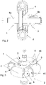
- 1 shows an expansion machine according to the invention in an isometric view
- 2 shows a sectional view of the impellers of the expander
- 3 shows an isometric view of the impellers according to FIG 2
- 4 shows an isometric view of the first impeller
- figure 5 shows an isometric view of the second impeller
- 6 shows an exploded view of the first impeller in isometric view
- 7 shows a view of the impellers, which are arranged in the housing
- 8 shows an isometric view of the torus half shells 17 with housing ring
- 9 shows a torus half shell in an isometric view
- 10 shows an isometric view of the transmission without showing the housing
- 11 shows a sectional view of the transmission
- 12 shows a sectional view through the expander with gear and in the 13 and 14 a schematic representation of an expansion process of the working medium.
- FIG. 1 1 is an isometric view of the expander 100 of the present invention.
- the expander 100 includes an expander unit 30 attached to a transmission 10 .
- the transmission 10 is in the Figures 1 to 12 preferred embodiment designed as a non-circular gear.
- Two feed lines 31 and two discharge lines 32 are arranged on the expansion machine 100 in each case.
- the working medium, in this embodiment hot, compressed steam, is introduced into the expansion machine 100 in the feed lines 31 , expanded in the expansion machine 100 and discharged from the expansion machine 100 as expanded steam or expanded working medium from the discharge lines 32 .
- the torque generated by the expansion of the steam is forwarded by the expansion unit 30 to the transmission 10 and used by it, for example, in a generator to generate electricity.
- the expansion machine 100 comprises two impellers 1, 2 ( 2 ).
- the first impeller 1 is mounted in the second impeller 2, so that the impellers 1, 2 are freely rotatable relative to one another.
- the shaft 6b of the second impeller 2 is designed as a hollow shaft, the first shaft 6a of the first impeller 1 being inserted into or arranged in the second shaft 6b of the second impeller 2 designed as a hollow shaft and being mounted together.
- the design of the impellers 1, 2 mounted one inside the other results in a particularly compact design that simply allows the first impeller 1 to move relative to the second impeller 2.
- the expansion machine 100 also has a housing 3 in which the impellers 1, 2 are mounted ( 1 , 8 ).
- the pistons 4 are designed in the shape of torus segments, i.e. have a circular cross section ( 2 ) and extend over a partial segment of the circumference of the respective impeller 1, 2.
- the pistons 4 are designed to be rotatable relative to one another along a toroidal raceway 16 in the axis of rotation of the impellers 1, 2.
- wing chambers 5 corresponding to the number of pistons 4 - ie four wing chambers 5 in this embodiment - are formed ( 7 ).
- the wing chambers 5 together with the pistons 4 and the housing 3 of the expansion machine 100 form a closed space in which the steam introduced through the supply line 31 via inlet channels 8 expands and applies a force or torque to the end face 45 of the pistons 4 .
- the expanded vapor then exits the expansion unit 3 of the expansion machine 100 again via the outlet channel 9 and the discharge lines 32 .
- the toroidal raceway 16 of the piston 4 is formed by two toroidal half-shells 17 ( 9 ), which are assembled one on top of the other and the raceway 16 of the pistons 4 ( 7 ) train.
- the torus half-shells 17 are held in position and centered by a housing ring 18 .
- the impeller chambers 5 are closed by housing covers 20 in the axial direction of the impellers 1 , 2 .
- Two inlet channels 8 and two outlet channels 9 are formed in each of the torus half-shells 17 and the housing ring 18 .
- Steam can flow into the respective vane chamber 5 via the inlet channels 8 , expand in the vane chamber 5 and then exit the expansion machine 100 again via the respective outlet channel 9 .
- the inlet channel 8 is designed to be smaller than the outlet channel 9 in accordance with the expansion ratio of the steam.
- the toroidal half-shell 17 has a toroidal depression which is designed to be the opposite of the piston 4 and which forms the raceway 16 of the piston 4 .
- the inlet channels 8 and the outlet channels 9 are arranged in the form of slots 19 formed in the circumference of the raceway 16 .
- the slots 19 run over a defined peripheral section of the toroidal raceway 16 of the pistons 4 corresponding to the inlet channels 8 and outlet channels 9 and are arranged parallel to one another and parallel to the plane formed by the pistons 4 .
- the transmission 10 shows a detailed view of the transmission 10 downstream of the expansion machine 100. Due to the relative rotatability of the impellers 1, 2 to one another, a torque generated by the steam expanding in the vane chambers 5 is transmitted to the transmission input shafts 11a, 11b of the transmission 10 via the shafts 6a, 6b. ( Fig.11 , 12 )
- the transmission 10 includes the same number of transmission input shafts 11a, 11b, which corresponds to the number of shafts 6a, 6b or the number of impellers 1, 2.
- the second transmission input shaft 11b is designed as a hollow shaft corresponding to the second shaft 6b and is connected to it in a torque-transmitting manner.
- the first transmission input shaft 11a is connected to the first shaft 6a of the first impeller 1 in a torque-transmitting manner and within it as a hollow shaft trained second transmission input shaft 11a arranged ( 12 ).
- An oval gear wheel 13, 14 is arranged on each of the transmission input shafts 11a, 11b, the oval gear wheels 13, 14 being oval in shape and offset from one another on the transmission input shafts 11a, 11b.
- the transmission 10 also has an output shaft 12, via which the torque introduced into the transmission 10 is output from the transmission 10, for example to a generator for generating electricity ( 11 , 12 ).
- On the output shaft 12 are two offset by 90 ° to each other and arranged eccentrically to the shaft axis of the output shaft 12 gears 15a, 15b.
- the gears 15a, 15b mesh with the oval gears 13, 14 and are in mesh with one of the oval gears 13, 14, respectively.
- the torque introduced at the second shaft 6b is delivered via the second oval gear 14 to the second gear 15b of the output shaft 12, summed with the torque of the first gear 15a and also derived via the output shaft 12 from the transmission 10.
- FIG. 12 a sectional view of the expander 100 according to the invention is shown.
- the transmission 10 is arranged on and connected to the expansion unit 30 .
- the shafts 6a, 6b are connected to the respective transmission input shafts 11a, 11b in a torque-transmitting manner via a toothing on the face side, in this embodiment a Hirth toothing, so that the torque introduced on the shafts 6a, 6b can be easily transmitted to the transmission input shafts 11a, 11b.
- the impellers 1, 2 each have two toroidal segment-shaped pistons 4, which are offset by 180 degrees with respect to the axis of rotation of the impellers 1, 2 on the respective shaft 6a, 6b.
- the pistons 4 are here via a non-positive connection - at this Embodiment via a screw - connected to the shafts 6a, 6b.
- the toroidal segment-shaped pistons 4 of the first impeller 1 have a kidney-shaped extension 41 which engages in a recess 42 of opposite design.
- the recess 42 is formed on a fastening extension 43 protruding from the first shaft 6a of the first impeller 1, the kidney-shaped extensions 41 of the pistons 4 being non-positively fastened to the fastening extension 43 via a screw connection.
- the pistons of the second impeller 2 can also be attached analogously to these.
- the pistons 4 of the expander 100 such as in 2 shown, hollow and are each closed at the front with a piston cover 44. Due to the hollow design of the pistons 4, a weight saving is achieved, which further leads to lower inertia forces on the impellers 1, 2.
- FIG. 1 to 12 a preferred embodiment of the expansion machine 100 with four pistons 4 is shown, whereby embodiments with one piston 4 arranged on the impellers 1, 2 or two pistons 4 of the expansion machine 100 in total or a higher number than four pistons 4, for example six, eight, ten or twelve pistons 4 can be provided.
- the expansion machine 100 is preferably used in a system for converting heat from a working medium, in particular steam, into mechanical work or is preferably arranged in such a system.
- the working medium compressed by a compressor is heated in a heat source and evaporated. This vapor is then conducted to the expansion machine 100 via lines.
- the working medium is then expanded in the expansion machine 100 and a force is applied to the end faces 45 of the pistons 4, which force is passed on to the shafts 6a, 6b as torque.
- This torque is then added together in the transmission 10 and delivered via the output shaft 12, for example to a generator or a downstream unit for generating electricity or further conversion.
- the expanded working medium is then condensed in a heat exchanger and returned to the compressor.
- other components such as superheaters or other heat exchangers can optionally also be provided.
- the transmission 10 may also have other configurations.
- the working medium can be ethanol or organic-based working media.
- FIG. 13 and 14 is a schematic representation during a working cycle of the working medium and the impellers 1, 2 are shown in two working positions.
- the angle between the pistons 4 of the impellers 1, 2 relative to one another is changed by the working medium that has flowed in via the inlet channels 8.
- the working medium that has entered the wing chambers 5 via the inlet channels 8 causes an angular change in the impellers 1, 2 relative to one another as a result of its expansion, so that the space between two wing chambers 5 is minimized and the space in the other two wing chambers 5, in which the working medium expands, is maximized ( 13 ).
- the wing chambers 5 overlap with the outlet channels 9 and the expanded working medium exits the wing chambers 5 and the previously compressed spaces of the other two wing chambers 5 expand again due to the working medium that has entered them via the inlet channels 8. This creates a cyclic change in the size of the vane chambers 5 due to the expansion of the working medium, and pressure is exerted on the pistons 4 or a torque is generated on the vane wheels 1, 2 and their shafts 6a, 6b.
Landscapes
- Engineering & Computer Science (AREA)
- Mechanical Engineering (AREA)
- General Engineering & Computer Science (AREA)
- Chemical & Material Sciences (AREA)
- Combustion & Propulsion (AREA)
- Hydraulic Motors (AREA)
- Structures Of Non-Positive Displacement Pumps (AREA)
- Wind Motors (AREA)
Applications Claiming Priority (1)
| Application Number | Priority Date | Filing Date | Title |
|---|---|---|---|
| ATA51085/2020A AT524617B1 (de) | 2020-12-14 | 2020-12-14 | Expansionsmaschine |
Publications (1)
| Publication Number | Publication Date |
|---|---|
| EP4012157A1 true EP4012157A1 (fr) | 2022-06-15 |
Family
ID=78844744
Family Applications (1)
| Application Number | Title | Priority Date | Filing Date |
|---|---|---|---|
| EP21213938.0A Withdrawn EP4012157A1 (fr) | 2020-12-14 | 2021-12-13 | Machine d'expansion |
Country Status (2)
| Country | Link |
|---|---|
| EP (1) | EP4012157A1 (fr) |
| AT (1) | AT524617B1 (fr) |
Citations (4)
| Publication number | Priority date | Publication date | Assignee | Title |
|---|---|---|---|---|
| US3398643A (en) * | 1965-07-30 | 1968-08-27 | Schudt Hans | Rotary piston engine, pump or other machine |
| US20070062482A1 (en) * | 2003-11-21 | 2007-03-22 | Anatoly Arov | Orbital engine/pump with multiple toroidal cylinders |
| US20110048370A1 (en) * | 2003-02-13 | 2011-03-03 | Vishvas Ambardekar | Revolving piston internal combustion engine |
| WO2014076637A1 (fr) * | 2012-11-15 | 2014-05-22 | I.V.A.R. S.P.A. | Dispositif d'expansion rotatif et centrale de cogénération d'énergie électrique et thermique comprenant le dispositif d'expansion rotatif |
Family Cites Families (1)
| Publication number | Priority date | Publication date | Assignee | Title |
|---|---|---|---|---|
| GB1068170A (en) * | 1963-01-22 | 1967-05-10 | Aero Commerce G M B H | Rotary piston machines |
-
2020
- 2020-12-14 AT ATA51085/2020A patent/AT524617B1/de active
-
2021
- 2021-12-13 EP EP21213938.0A patent/EP4012157A1/fr not_active Withdrawn
Patent Citations (4)
| Publication number | Priority date | Publication date | Assignee | Title |
|---|---|---|---|---|
| US3398643A (en) * | 1965-07-30 | 1968-08-27 | Schudt Hans | Rotary piston engine, pump or other machine |
| US20110048370A1 (en) * | 2003-02-13 | 2011-03-03 | Vishvas Ambardekar | Revolving piston internal combustion engine |
| US20070062482A1 (en) * | 2003-11-21 | 2007-03-22 | Anatoly Arov | Orbital engine/pump with multiple toroidal cylinders |
| WO2014076637A1 (fr) * | 2012-11-15 | 2014-05-22 | I.V.A.R. S.P.A. | Dispositif d'expansion rotatif et centrale de cogénération d'énergie électrique et thermique comprenant le dispositif d'expansion rotatif |
Also Published As
| Publication number | Publication date |
|---|---|
| AT524617B1 (de) | 2023-05-15 |
| AT524617A1 (de) | 2022-07-15 |
Similar Documents
| Publication | Publication Date | Title |
|---|---|---|
| DE112013006341T5 (de) | Abgas-Energierückgewinnungssystem | |
| DE102011083918A1 (de) | Drehmodulationsmotor | |
| DE102009038786A1 (de) | Verdichter | |
| WO2023237152A1 (fr) | Système d'entraînement pour aéronef | |
| DE102022115587A1 (de) | Antriebssystem für ein Luftfahrzeug | |
| DE3510492A1 (de) | Verfahren und vorrichtung zur kraftuebertragung | |
| EP0369991A1 (fr) | Moteur alternatif à pistons tournant | |
| DE102008050014A1 (de) | Zink'sche Tangential-Verbrennung Turbine | |
| EP3214262A2 (fr) | Unité moteur-compresseur | |
| AT524617B1 (de) | Expansionsmaschine | |
| WO2023237151A1 (fr) | Système de propulsion pour aéronef | |
| WO2015010780A2 (fr) | Machine à piston rotatif | |
| WO1995034750A1 (fr) | Moteur a combustion interne, compresseur ou pompe | |
| DE1426773A1 (de) | Drehantriebsvorrichtung | |
| CH664193A5 (de) | Abgasbetriebener rotationskolbenlader. | |
| DE102006018183A1 (de) | Drehkolbenmaschine | |
| EP0130436A1 (fr) | Machine à piston rotatif utilisée comme machine à expansion ou compresseur | |
| DE2619474A1 (de) | Leistungsgenerator | |
| DE69304310T2 (de) | Turbine | |
| DE4419616C1 (de) | Innenachsige achsenparallele Drehkolbenmalschine | |
| EP3717771B1 (fr) | Fixation d'un tube pour conduits | |
| DE102009052960B4 (de) | Freikolben-Brennkraftmaschine | |
| DE19827474C2 (de) | Wärmemaschinenvorrichtung | |
| DE2918369A1 (de) | Rotations-expansionsmaschine | |
| DE202009017893U1 (de) | Verbrennungsmotor |
Legal Events
| Date | Code | Title | Description |
|---|---|---|---|
| PUAI | Public reference made under article 153(3) epc to a published international application that has entered the european phase |
Free format text: ORIGINAL CODE: 0009012 |
|
| STAA | Information on the status of an ep patent application or granted ep patent |
Free format text: STATUS: THE APPLICATION HAS BEEN PUBLISHED |
|
| AK | Designated contracting states |
Kind code of ref document: A1 Designated state(s): AL AT BE BG CH CY CZ DE DK EE ES FI FR GB GR HR HU IE IS IT LI LT LU LV MC MK MT NL NO PL PT RO RS SE SI SK SM TR |
|
| STAA | Information on the status of an ep patent application or granted ep patent |
Free format text: STATUS: REQUEST FOR EXAMINATION WAS MADE |
|
| 17P | Request for examination filed |
Effective date: 20221215 |
|
| RBV | Designated contracting states (corrected) |
Designated state(s): AL AT BE BG CH CY CZ DE DK EE ES FI FR GB GR HR HU IE IS IT LI LT LU LV MC MK MT NL NO PL PT RO RS SE SI SK SM TR |
|
| STAA | Information on the status of an ep patent application or granted ep patent |
Free format text: STATUS: THE APPLICATION IS DEEMED TO BE WITHDRAWN |
|
| 18D | Application deemed to be withdrawn |
Effective date: 20221216 |