EP4012159B1 - Élément d'amortissement pour une aube de turbine à vapeur - Google Patents
Élément d'amortissement pour une aube de turbine à vapeur Download PDFInfo
- Publication number
- EP4012159B1 EP4012159B1 EP21209690.3A EP21209690A EP4012159B1 EP 4012159 B1 EP4012159 B1 EP 4012159B1 EP 21209690 A EP21209690 A EP 21209690A EP 4012159 B1 EP4012159 B1 EP 4012159B1
- Authority
- EP
- European Patent Office
- Prior art keywords
- coupling
- turbine
- coupling element
- turbine blades
- turbine blade
- Prior art date
- Legal status (The legal status is an assumption and is not a legal conclusion. Google has not performed a legal analysis and makes no representation as to the accuracy of the status listed.)
- Active
Links
Images

Classifications
-
- F—MECHANICAL ENGINEERING; LIGHTING; HEATING; WEAPONS; BLASTING
- F01—MACHINES OR ENGINES IN GENERAL; ENGINE PLANTS IN GENERAL; STEAM ENGINES
- F01D—NON-POSITIVE DISPLACEMENT MACHINES OR ENGINES, e.g. STEAM TURBINES
- F01D5/00—Blades; Blade-carrying members; Heating, heat-insulating, cooling or antivibration means on the blades or the members
- F01D5/12—Blades
- F01D5/22—Blade-to-blade connections, e.g. for damping vibrations
-
- F—MECHANICAL ENGINEERING; LIGHTING; HEATING; WEAPONS; BLASTING
- F01—MACHINES OR ENGINES IN GENERAL; ENGINE PLANTS IN GENERAL; STEAM ENGINES
- F01D—NON-POSITIVE DISPLACEMENT MACHINES OR ENGINES, e.g. STEAM TURBINES
- F01D5/00—Blades; Blade-carrying members; Heating, heat-insulating, cooling or antivibration means on the blades or the members
- F01D5/12—Blades
- F01D5/26—Antivibration means not restricted to blade form or construction or to blade-to-blade connections or to the use of particular materials
Definitions
- the invention relates to a turbine stage, comprising at least one turbine rotor and a plurality of turbine blades arranged around the circumference of the turbine rotor, and at least one coupling element, through-holes being formed in a first turbine blade and in a second turbine blade adjacent to the first, through which the coupling element protrudes and wherein the coupling element mechanically couples the turbine blades to one another.
- the permanently drivable operating range must be significantly restricted in some cases (e.g. lowering the pressure protection curve) in order to ensure the mechanical integrity of the blading and to avoid a functional failure or even more serious consequences due to blade loss.
- One way to avoid blade vibrations or at least to reduce them is to use coupling elements that are arranged between two turbine blades and mechanically couple them to each other. Energy, which causes the blades to vibrate, is withdrawn from the system by means of the coupling elements and dissipated by friction effects.
- Such coupling elements are, for example, from DE 10 2010 041 702 A1 known.
- the coupling of two or more turbine blades by means of coupling elements significantly reduces the vibration amplitude of the individual blades and thereby reduces the vibration load in the individual blades, so that fatigue fractures of the turbine blades can be effectively prevented.
- the DE 10 2017 203 308 A1 discloses a turbine stage in which the coupling elements are to be spatially arranged in such a way that they can be removed without dismantling the individual turbine blades of the turbine stage.
- a turbine blade has a through hole and the adjacent turbine blade to be coupled has a blind hole.
- the coupling element is pushed through the through hole until it is located with a first end in the blind hole.
- a closure element is then screwed into the through hole, which fixes the second end of the coupling element.
- screwing in the closure element results in notch stresses in the blade area due to the internal thread, which can lead to local stress increases and failure of the turbine blade.
- the outside of the respective turbine blade is the side of the turbine blade (turbine profile) that faces away from the second turbine blade to be coupled.
- the two turbine blades only have through holes and the two components (coupling pin with coupling sleeve) of the coupling element are only screwed to themselves, no special design or minimum thickness of the turbine blades is necessary. In principle, this means that any existing turbine stage can be easily retrofitted. Because the coupling element is only pushed through the through bores in the turbine blades, there are no notch stresses as in a solution with a closure element screwed into the turbine blade, which would not lead to any weakening of the turbine blade.
- An embodiment of the invention provides that the coupling sleeve protrudes through the through hole of both the first and the second turbine blade.
- the through bores in both turbine blades can be formed with the same diameter, which simplifies production and saves costs. In addition, this simplifies assembly, since all turbine blades are of identical design and a specific sequence does not have to be observed during assembly.
- a further embodiment of the invention provides that the end of the coupling pin opposite the second contact head is plastically deformed, so that there is a form fit between the coupling pin and the coupling sleeve. This prevents the screw connection between the coupling pin and the coupling sleeve from loosening during turbine operation.
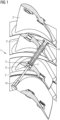
- FIG. 1 shows an embodiment of a turbine stage according to the invention.
- the figure does not show the complete turbine stage, but only a section necessary to illustrate the invention.
- the figure is shown as a development.
- the turbine stage 1 comprises a turbine rotor 2 and a plurality of turbine blades 3 arranged around the circumference of the turbine rotor 2. Two adjacent turbine blades 3', 3" are mechanically coupled to one another by means of a coupling element 4.
- the turbine blade has a corresponding through hole 5 through which
- the coupling element 4 comprises a coupling sleeve 6 and a coupling pin 10 which are screwed together in the assembled state.
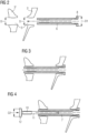
- the mechanical coupling ensures that the turbine blades 3′, 3′′ are not excited to vibrate, which can lead to damage to the turbine blades or a reduction in the service life of the components Figures 2-7 explained.
- the coupling sleeve 6 When mounting the coupling element 4, the coupling sleeve 6 is first pushed through the bores 5 in the first turbine blade 3' and the second turbine blade 3".
- the bores 5 preferably have the same diameter D in both turbine blades 3', 3".
- all turbine blades of a turbine stage can be of identical design.
- the coupling sleeve 6 has a contact head 8 at one end, the diameter D1 of which is larger than the diameter D of the bores 5 in the turbine blades 3', 3". As a result, the coupling sleeve 6 cannot be pushed through the bore when it is pushed into the bores 5 become.
- the coupling pin 10 is screwed into the coupling sleeve 6 .
- an internal thread 7 is formed in the coupling sleeve 6 and a complementary external thread 11 is formed on the coupling pin 10 .
- the coupling pin 10 has a contact head 12 whose diameter D2 is in turn larger than the diameter D of the bores 5. This ensures that the coupling element 4 after the coupling sleeve 6 has been screwed to the coupling pin 10 is mounted captively between the two turbine blades 3', 3".
- the coupling element After assembly and when the turbine stage is at a standstill, the coupling element has a certain amount of play and can thus be displaced both in the axial and in the radial direction. During operation of the turbine, it settles the coupling element 4 due to the centrifugal force to the bores 5 and ensures the mechanical coupling of the two turbine blades 3 'and 3' and thus for vibration damping.
- figure 5 shows the coupling element 4 in the assembled state.
Landscapes
- Engineering & Computer Science (AREA)
- Mechanical Engineering (AREA)
- General Engineering & Computer Science (AREA)
- Turbine Rotor Nozzle Sealing (AREA)
Claims (3)
- Étage de turbine (1), comprenant au moins un rotor de turbine (2) et plusieurs aubes de turbine (3) agencées sur la périphérie du rotor de turbine (2), ainsi qu'au moins un élément de couplage (4),dans lequel des alésages traversants (5) à travers lesquels fait saillie l'élément de couplage (4) sont formés dans une première aube de turbine (3') et dans une seconde aube de turbine (3") voisine de la première, etdans lequel l'élément de couplage (4) couple mécaniquement les aubes de turbine (3',3") l'une à l'autre,caractérisé en ce que l'élément de couplage (4)- présente un manchon de couplage (6) avec un filetage intérieur (7) et une première tête d'appui (8) formée à une extrémité du manchon de couplage (6), dans lequel la première tête d'appui (8) présente un diamètre (D1) supérieur au diamètre (D) de l'alésage traversant (5) à travers lequel l'élément de couplage (4) fait saillie, et dans lequel la première tête d'appui (8) est agencée sur le côté extérieur (9) de la première aube de turbine (3'),- présente une tige de couplage (10) avec un filetage extérieur (11) réalisé de manière complémentaire au filetage intérieur (7) du manchon de couplage (6) et une seconde tête d'appui (12) réalisée à une extrémité de la tige de couplage (10), dans lequel la seconde tête d'appui (12) présente un diamètre (D2) supérieur au diamètre (D) de l'alésage traversant (5) à travers lequel l'élément de couplage (4) fait saillie, et dans lequel la seconde tête d'appui (12) est agencée sur le côté extérieur (13) de la seconde aube de turbine (3"), et dans lequel le manchon de couplage (6) et la tige de couplage (10) sont vissés l'un à l'autre par l'intermédiaire du filetage interne (7) et du filetage externe (11).
- Étage de turbine selon la revendication 1, caractérisé en ce que le manchon de couplage (6) fait saillie à travers l'alésage traversant (5) des première et seconde aubes de turbine (3', 3").
- Étage de turbine selon la revendication 1, caractérisé en ce que l'extrémité de la tige de couplage (10) opposée à la seconde tête d'appui (9) est déformée de manière plastique de sorte qu'un verrouillage par complémentarité de forme est constitué entre la tige de couplage (8) et le manchon de couplage (5).
Applications Claiming Priority (1)
| Application Number | Priority Date | Filing Date | Title |
|---|---|---|---|
| DE102020215479.1A DE102020215479A1 (de) | 2020-12-08 | 2020-12-08 | Neuartiges Dämpfungselement für Dampfturbinenschaufeln |
Publications (2)
| Publication Number | Publication Date |
|---|---|
| EP4012159A1 EP4012159A1 (fr) | 2022-06-15 |
| EP4012159B1 true EP4012159B1 (fr) | 2023-06-07 |
Family
ID=78725380
Family Applications (1)
| Application Number | Title | Priority Date | Filing Date |
|---|---|---|---|
| EP21209690.3A Active EP4012159B1 (fr) | 2020-12-08 | 2021-11-22 | Élément d'amortissement pour une aube de turbine à vapeur |
Country Status (3)
| Country | Link |
|---|---|
| EP (1) | EP4012159B1 (fr) |
| DE (1) | DE102020215479A1 (fr) |
| PL (1) | PL4012159T3 (fr) |
Family Cites Families (4)
| Publication number | Priority date | Publication date | Assignee | Title |
|---|---|---|---|---|
| US4776764A (en) * | 1987-04-02 | 1988-10-11 | Ortolano Ralph J | Structure for an axial flow elastic fluid utilizing machine |
| DE3810537A1 (de) | 1988-03-28 | 1989-10-19 | Semm Tec Computerentwicklung V | Schwingungsdaempfung fuer axialbeschaufelungen |
| DE102010041702A1 (de) | 2010-09-30 | 2012-04-05 | Siemens Aktiengesellschaft | Koppelbolzen für Turbinenschaufeln |
| DE102017203308A1 (de) | 2017-03-01 | 2018-09-06 | Siemens Aktiengesellschaft | Turbinenstufe mit Koppelelement |
-
2020
- 2020-12-08 DE DE102020215479.1A patent/DE102020215479A1/de not_active Ceased
-
2021
- 2021-11-22 PL PL21209690.3T patent/PL4012159T3/pl unknown
- 2021-11-22 EP EP21209690.3A patent/EP4012159B1/fr active Active
Also Published As
| Publication number | Publication date |
|---|---|
| PL4012159T3 (pl) | 2023-10-16 |
| DE102020215479A1 (de) | 2022-06-09 |
| EP4012159A1 (fr) | 2022-06-15 |
Similar Documents
| Publication | Publication Date | Title |
|---|---|---|
| CH714160A2 (de) | Verschalung eines Turboladers und Turbolader. | |
| WO2000000719A1 (fr) | Rotor pour turbomachine | |
| DE69913625T2 (de) | Gasturbine | |
| WO2005093286A1 (fr) | Arbre d'equilibrage pour un moteur a plusieurs cylindres en ligne | |
| CH714607B1 (de) | Verschalung für einen Turbolader und Turbolader. | |
| DE3417555A1 (de) | Vibrationsanordnung mit einer mehrzahl von vibrationsamplituden | |
| EP1076184A2 (fr) | Dispositf de fixation | |
| WO2009043398A1 (fr) | Disque de frein | |
| EP4526563B1 (fr) | Carter de boîte de vitesses monté sur ressort | |
| EP3390784B1 (fr) | Turbomachine à plusieurs étages d'aubes directrices et procédé pour démonter en partie une telle turbomachine | |
| WO1985005420A1 (fr) | Accouplement rigide en torsion et flexible axialement | |
| EP3276197B1 (fr) | Dispositif de fixation de palier pour un palier monté en rotation sur un arbre | |
| EP4012159A1 (fr) | Élément d'amortissement pour une aube de turbine à vapeur | |
| EP2480791A1 (fr) | Turbomachine axiale-radiale | |
| EP3775532B1 (fr) | Pale de rotor d'éolienne et éolienne | |
| WO2018157958A1 (fr) | Étage de turbine muni d'un élément d'accouplement | |
| DE69517779T2 (de) | Elastische Kupplung für drehende Wellen | |
| EP2436878B1 (fr) | Boulons de couplage pour aubes de turbines | |
| DE102013017713B4 (de) | Turbomaschine | |
| DE102009053000B4 (de) | Fanrückhaltescheibe für ein Strahltriebwerk | |
| DE102010010712B4 (de) | Halter zur Montage von Anbauteilen am Gehäuse eines Triebwerks, insbesondere eines Strahltriebwerks | |
| EP1714007A1 (fr) | Dispositif de suspension d'aubes directrices | |
| EP4088010B1 (fr) | Procédé pour assurer provisoirement la capacité fonctionnelle d'un boîtier endommagé, et boîtier | |
| WO2020058104A1 (fr) | Système de palier de pale pour une éolienne, éolienne et procédé de fabrication d'un système de palier de pale | |
| DE202019102568U1 (de) | Turbolader und Träger zur Anbindung einer Baugruppe an einen Turbolader |
Legal Events
| Date | Code | Title | Description |
|---|---|---|---|
| PUAI | Public reference made under article 153(3) epc to a published international application that has entered the european phase |
Free format text: ORIGINAL CODE: 0009012 |
|
| STAA | Information on the status of an ep patent application or granted ep patent |
Free format text: STATUS: THE APPLICATION HAS BEEN PUBLISHED |
|
| STAA | Information on the status of an ep patent application or granted ep patent |
Free format text: STATUS: REQUEST FOR EXAMINATION WAS MADE |
|
| AK | Designated contracting states |
Kind code of ref document: A1 Designated state(s): AL AT BE BG CH CY CZ DE DK EE ES FI FR GB GR HR HU IE IS IT LI LT LU LV MC MK MT NL NO PL PT RO RS SE SI SK SM TR |
|
| 17P | Request for examination filed |
Effective date: 20220524 |
|
| RBV | Designated contracting states (corrected) |
Designated state(s): AL AT BE BG CH CY CZ DE DK EE ES FI FR GB GR HR HU IE IS IT LI LT LU LV MC MK MT NL NO PL PT RO RS SE SI SK SM TR |
|
| RIC1 | Information provided on ipc code assigned before grant |
Ipc: F01D 5/26 20060101ALI20221026BHEP Ipc: F01D 5/22 20060101AFI20221026BHEP |
|
| GRAP | Despatch of communication of intention to grant a patent |
Free format text: ORIGINAL CODE: EPIDOSNIGR1 |
|
| STAA | Information on the status of an ep patent application or granted ep patent |
Free format text: STATUS: GRANT OF PATENT IS INTENDED |
|
| INTG | Intention to grant announced |
Effective date: 20221223 |
|
| GRAS | Grant fee paid |
Free format text: ORIGINAL CODE: EPIDOSNIGR3 |
|
| GRAA | (expected) grant |
Free format text: ORIGINAL CODE: 0009210 |
|
| STAA | Information on the status of an ep patent application or granted ep patent |
Free format text: STATUS: THE PATENT HAS BEEN GRANTED |
|
| AK | Designated contracting states |
Kind code of ref document: B1 Designated state(s): AL AT BE BG CH CY CZ DE DK EE ES FI FR GB GR HR HU IE IS IT LI LT LU LV MC MK MT NL NO PL PT RO RS SE SI SK SM TR |
|
| REG | Reference to a national code |
Ref country code: GB Ref legal event code: FG4D Free format text: NOT ENGLISH |
|
| REG | Reference to a national code |
Ref country code: CH Ref legal event code: EP Ref country code: AT Ref legal event code: REF Ref document number: 1575701 Country of ref document: AT Kind code of ref document: T Effective date: 20230615 Ref country code: DE Ref legal event code: R096 Ref document number: 502021000827 Country of ref document: DE |
|
| REG | Reference to a national code |
Ref country code: LT Ref legal event code: MG9D |
|
| REG | Reference to a national code |
Ref country code: NL Ref legal event code: MP Effective date: 20230607 |
|
| PG25 | Lapsed in a contracting state [announced via postgrant information from national office to epo] |
Ref country code: SE Free format text: LAPSE BECAUSE OF FAILURE TO SUBMIT A TRANSLATION OF THE DESCRIPTION OR TO PAY THE FEE WITHIN THE PRESCRIBED TIME-LIMIT Effective date: 20230607 Ref country code: NO Free format text: LAPSE BECAUSE OF FAILURE TO SUBMIT A TRANSLATION OF THE DESCRIPTION OR TO PAY THE FEE WITHIN THE PRESCRIBED TIME-LIMIT Effective date: 20230907 Ref country code: ES Free format text: LAPSE BECAUSE OF FAILURE TO SUBMIT A TRANSLATION OF THE DESCRIPTION OR TO PAY THE FEE WITHIN THE PRESCRIBED TIME-LIMIT Effective date: 20230607 |
|
| PG25 | Lapsed in a contracting state [announced via postgrant information from national office to epo] |
Ref country code: RS Free format text: LAPSE BECAUSE OF FAILURE TO SUBMIT A TRANSLATION OF THE DESCRIPTION OR TO PAY THE FEE WITHIN THE PRESCRIBED TIME-LIMIT Effective date: 20230607 Ref country code: NL Free format text: LAPSE BECAUSE OF FAILURE TO SUBMIT A TRANSLATION OF THE DESCRIPTION OR TO PAY THE FEE WITHIN THE PRESCRIBED TIME-LIMIT Effective date: 20230607 Ref country code: LV Free format text: LAPSE BECAUSE OF FAILURE TO SUBMIT A TRANSLATION OF THE DESCRIPTION OR TO PAY THE FEE WITHIN THE PRESCRIBED TIME-LIMIT Effective date: 20230607 Ref country code: LT Free format text: LAPSE BECAUSE OF FAILURE TO SUBMIT A TRANSLATION OF THE DESCRIPTION OR TO PAY THE FEE WITHIN THE PRESCRIBED TIME-LIMIT Effective date: 20230607 Ref country code: HR Free format text: LAPSE BECAUSE OF FAILURE TO SUBMIT A TRANSLATION OF THE DESCRIPTION OR TO PAY THE FEE WITHIN THE PRESCRIBED TIME-LIMIT Effective date: 20230607 Ref country code: GR Free format text: LAPSE BECAUSE OF FAILURE TO SUBMIT A TRANSLATION OF THE DESCRIPTION OR TO PAY THE FEE WITHIN THE PRESCRIBED TIME-LIMIT Effective date: 20230908 |
|
| PG25 | Lapsed in a contracting state [announced via postgrant information from national office to epo] |
Ref country code: FI Free format text: LAPSE BECAUSE OF FAILURE TO SUBMIT A TRANSLATION OF THE DESCRIPTION OR TO PAY THE FEE WITHIN THE PRESCRIBED TIME-LIMIT Effective date: 20230607 |
|
| PG25 | Lapsed in a contracting state [announced via postgrant information from national office to epo] |
Ref country code: SK Free format text: LAPSE BECAUSE OF FAILURE TO SUBMIT A TRANSLATION OF THE DESCRIPTION OR TO PAY THE FEE WITHIN THE PRESCRIBED TIME-LIMIT Effective date: 20230607 |
|
| PG25 | Lapsed in a contracting state [announced via postgrant information from national office to epo] |
Ref country code: IS Free format text: LAPSE BECAUSE OF FAILURE TO SUBMIT A TRANSLATION OF THE DESCRIPTION OR TO PAY THE FEE WITHIN THE PRESCRIBED TIME-LIMIT Effective date: 20231007 |
|
| PG25 | Lapsed in a contracting state [announced via postgrant information from national office to epo] |
Ref country code: SM Free format text: LAPSE BECAUSE OF FAILURE TO SUBMIT A TRANSLATION OF THE DESCRIPTION OR TO PAY THE FEE WITHIN THE PRESCRIBED TIME-LIMIT Effective date: 20230607 Ref country code: SK Free format text: LAPSE BECAUSE OF FAILURE TO SUBMIT A TRANSLATION OF THE DESCRIPTION OR TO PAY THE FEE WITHIN THE PRESCRIBED TIME-LIMIT Effective date: 20230607 Ref country code: RO Free format text: LAPSE BECAUSE OF FAILURE TO SUBMIT A TRANSLATION OF THE DESCRIPTION OR TO PAY THE FEE WITHIN THE PRESCRIBED TIME-LIMIT Effective date: 20230607 Ref country code: PT Free format text: LAPSE BECAUSE OF FAILURE TO SUBMIT A TRANSLATION OF THE DESCRIPTION OR TO PAY THE FEE WITHIN THE PRESCRIBED TIME-LIMIT Effective date: 20231009 Ref country code: IS Free format text: LAPSE BECAUSE OF FAILURE TO SUBMIT A TRANSLATION OF THE DESCRIPTION OR TO PAY THE FEE WITHIN THE PRESCRIBED TIME-LIMIT Effective date: 20231007 Ref country code: EE Free format text: LAPSE BECAUSE OF FAILURE TO SUBMIT A TRANSLATION OF THE DESCRIPTION OR TO PAY THE FEE WITHIN THE PRESCRIBED TIME-LIMIT Effective date: 20230607 |
|
| REG | Reference to a national code |
Ref country code: DE Ref legal event code: R097 Ref document number: 502021000827 Country of ref document: DE |
|
| PLBE | No opposition filed within time limit |
Free format text: ORIGINAL CODE: 0009261 |
|
| STAA | Information on the status of an ep patent application or granted ep patent |
Free format text: STATUS: NO OPPOSITION FILED WITHIN TIME LIMIT |
|
| PG25 | Lapsed in a contracting state [announced via postgrant information from national office to epo] |
Ref country code: DK Free format text: LAPSE BECAUSE OF FAILURE TO SUBMIT A TRANSLATION OF THE DESCRIPTION OR TO PAY THE FEE WITHIN THE PRESCRIBED TIME-LIMIT Effective date: 20230607 |
|
| PG25 | Lapsed in a contracting state [announced via postgrant information from national office to epo] |
Ref country code: SI Free format text: LAPSE BECAUSE OF FAILURE TO SUBMIT A TRANSLATION OF THE DESCRIPTION OR TO PAY THE FEE WITHIN THE PRESCRIBED TIME-LIMIT Effective date: 20230607 |
|
| 26N | No opposition filed |
Effective date: 20240308 |
|
| PG25 | Lapsed in a contracting state [announced via postgrant information from national office to epo] |
Ref country code: SI Free format text: LAPSE BECAUSE OF FAILURE TO SUBMIT A TRANSLATION OF THE DESCRIPTION OR TO PAY THE FEE WITHIN THE PRESCRIBED TIME-LIMIT Effective date: 20230607 |
|
| PG25 | Lapsed in a contracting state [announced via postgrant information from national office to epo] |
Ref country code: MC Free format text: LAPSE BECAUSE OF FAILURE TO SUBMIT A TRANSLATION OF THE DESCRIPTION OR TO PAY THE FEE WITHIN THE PRESCRIBED TIME-LIMIT Effective date: 20230607 |
|
| PG25 | Lapsed in a contracting state [announced via postgrant information from national office to epo] |
Ref country code: LU Free format text: LAPSE BECAUSE OF NON-PAYMENT OF DUE FEES Effective date: 20231122 |
|
| PG25 | Lapsed in a contracting state [announced via postgrant information from national office to epo] |
Ref country code: MC Free format text: LAPSE BECAUSE OF FAILURE TO SUBMIT A TRANSLATION OF THE DESCRIPTION OR TO PAY THE FEE WITHIN THE PRESCRIBED TIME-LIMIT Effective date: 20230607 Ref country code: LU Free format text: LAPSE BECAUSE OF NON-PAYMENT OF DUE FEES Effective date: 20231122 |
|
| REG | Reference to a national code |
Ref country code: BE Ref legal event code: MM Effective date: 20231130 |
|
| REG | Reference to a national code |
Ref country code: IE Ref legal event code: MM4A |
|
| PG25 | Lapsed in a contracting state [announced via postgrant information from national office to epo] |
Ref country code: IE Free format text: LAPSE BECAUSE OF NON-PAYMENT OF DUE FEES Effective date: 20231122 |
|
| PG25 | Lapsed in a contracting state [announced via postgrant information from national office to epo] |
Ref country code: BE Free format text: LAPSE BECAUSE OF NON-PAYMENT OF DUE FEES Effective date: 20231130 |
|
| PG25 | Lapsed in a contracting state [announced via postgrant information from national office to epo] |
Ref country code: IE Free format text: LAPSE BECAUSE OF NON-PAYMENT OF DUE FEES Effective date: 20231122 Ref country code: BE Free format text: LAPSE BECAUSE OF NON-PAYMENT OF DUE FEES Effective date: 20231130 |
|
| PG25 | Lapsed in a contracting state [announced via postgrant information from national office to epo] |
Ref country code: BG Free format text: LAPSE BECAUSE OF FAILURE TO SUBMIT A TRANSLATION OF THE DESCRIPTION OR TO PAY THE FEE WITHIN THE PRESCRIBED TIME-LIMIT Effective date: 20230607 |
|
| PG25 | Lapsed in a contracting state [announced via postgrant information from national office to epo] |
Ref country code: BG Free format text: LAPSE BECAUSE OF FAILURE TO SUBMIT A TRANSLATION OF THE DESCRIPTION OR TO PAY THE FEE WITHIN THE PRESCRIBED TIME-LIMIT Effective date: 20230607 |
|
| REG | Reference to a national code |
Ref country code: CH Ref legal event code: PL |
|
| REG | Reference to a national code |
Ref country code: CH Ref legal event code: PL |
|
| PG25 | Lapsed in a contracting state [announced via postgrant information from national office to epo] |
Ref country code: CH Free format text: LAPSE BECAUSE OF NON-PAYMENT OF DUE FEES Effective date: 20241130 |
|
| PG25 | Lapsed in a contracting state [announced via postgrant information from national office to epo] |
Ref country code: CY Free format text: LAPSE BECAUSE OF FAILURE TO SUBMIT A TRANSLATION OF THE DESCRIPTION OR TO PAY THE FEE WITHIN THE PRESCRIBED TIME-LIMIT; INVALID AB INITIO Effective date: 20211122 |
|
| PG25 | Lapsed in a contracting state [announced via postgrant information from national office to epo] |
Ref country code: TR Free format text: LAPSE BECAUSE OF FAILURE TO SUBMIT A TRANSLATION OF THE DESCRIPTION OR TO PAY THE FEE WITHIN THE PRESCRIBED TIME-LIMIT Effective date: 20230607 |
|
| PGFP | Annual fee paid to national office [announced via postgrant information from national office to epo] |
Ref country code: DE Payment date: 20251126 Year of fee payment: 5 |
|
| PGFP | Annual fee paid to national office [announced via postgrant information from national office to epo] |
Ref country code: AT Payment date: 20260113 Year of fee payment: 5 |
|
| PGFP | Annual fee paid to national office [announced via postgrant information from national office to epo] |
Ref country code: IT Payment date: 20251121 Year of fee payment: 5 |
|
| PGFP | Annual fee paid to national office [announced via postgrant information from national office to epo] |
Ref country code: FR Payment date: 20251124 Year of fee payment: 5 |
|
| PGFP | Annual fee paid to national office [announced via postgrant information from national office to epo] |
Ref country code: CZ Payment date: 20251111 Year of fee payment: 5 |
|
| PGFP | Annual fee paid to national office [announced via postgrant information from national office to epo] |
Ref country code: PL Payment date: 20251028 Year of fee payment: 5 |
|
| PG25 | Lapsed in a contracting state [announced via postgrant information from national office to epo] |
Ref country code: HU Free format text: LAPSE BECAUSE OF FAILURE TO SUBMIT A TRANSLATION OF THE DESCRIPTION OR TO PAY THE FEE WITHIN THE PRESCRIBED TIME-LIMIT; INVALID AB INITIO Effective date: 20211122 |