EP4012176A1 - Dispositif de transport de matières épaisses - Google Patents
Dispositif de transport de matières épaisses Download PDFInfo
- Publication number
- EP4012176A1 EP4012176A1 EP21203291.6A EP21203291A EP4012176A1 EP 4012176 A1 EP4012176 A1 EP 4012176A1 EP 21203291 A EP21203291 A EP 21203291A EP 4012176 A1 EP4012176 A1 EP 4012176A1
- Authority
- EP
- European Patent Office
- Prior art keywords
- thick matter
- shaft
- bearing
- conveying device
- delivery
- Prior art date
- Legal status (The legal status is an assumption and is not a legal conclusion. Google has not performed a legal analysis and makes no representation as to the accuracy of the status listed.)
- Granted
Links
Images


Classifications
-
- F—MECHANICAL ENGINEERING; LIGHTING; HEATING; WEAPONS; BLASTING
- F04—POSITIVE - DISPLACEMENT MACHINES FOR LIQUIDS; PUMPS FOR LIQUIDS OR ELASTIC FLUIDS
- F04B—POSITIVE-DISPLACEMENT MACHINES FOR LIQUIDS; PUMPS
- F04B7/00—Piston machines or pumps characterised by having positively-driven valving
- F04B7/0019—Piston machines or pumps characterised by having positively-driven valving a common distribution member forming a single discharge distributor for a plurality of pumping chambers
- F04B7/0026—Piston machines or pumps characterised by having positively-driven valving a common distribution member forming a single discharge distributor for a plurality of pumping chambers and having an oscillating movement
-
- F—MECHANICAL ENGINEERING; LIGHTING; HEATING; WEAPONS; BLASTING
- F04—POSITIVE - DISPLACEMENT MACHINES FOR LIQUIDS; PUMPS FOR LIQUIDS OR ELASTIC FLUIDS
- F04B—POSITIVE-DISPLACEMENT MACHINES FOR LIQUIDS; PUMPS
- F04B15/00—Pumps adapted to handle specific fluids, e.g. by selection of specific materials for pumps or pump parts
- F04B15/02—Pumps adapted to handle specific fluids, e.g. by selection of specific materials for pumps or pump parts the fluids being viscous or non-homogeneous
- F04B15/023—Pumps adapted to handle specific fluids, e.g. by selection of specific materials for pumps or pump parts the fluids being viscous or non-homogeneous supply of fluid to the pump by gravity through a hopper, e.g. without intake valve
-
- F—MECHANICAL ENGINEERING; LIGHTING; HEATING; WEAPONS; BLASTING
- F04—POSITIVE - DISPLACEMENT MACHINES FOR LIQUIDS; PUMPS FOR LIQUIDS OR ELASTIC FLUIDS
- F04B—POSITIVE-DISPLACEMENT MACHINES FOR LIQUIDS; PUMPS
- F04B7/00—Piston machines or pumps characterised by having positively-driven valving
- F04B7/0019—Piston machines or pumps characterised by having positively-driven valving a common distribution member forming a single discharge distributor for a plurality of pumping chambers
- F04B7/0034—Piston machines or pumps characterised by having positively-driven valving a common distribution member forming a single discharge distributor for a plurality of pumping chambers and having an orbital movement, e.g. elbow-pipe type members
-
- F—MECHANICAL ENGINEERING; LIGHTING; HEATING; WEAPONS; BLASTING
- F04—POSITIVE - DISPLACEMENT MACHINES FOR LIQUIDS; PUMPS FOR LIQUIDS OR ELASTIC FLUIDS
- F04B—POSITIVE-DISPLACEMENT MACHINES FOR LIQUIDS; PUMPS
- F04B7/00—Piston machines or pumps characterised by having positively-driven valving
- F04B7/02—Piston machines or pumps characterised by having positively-driven valving the valving being fluid-actuated
- F04B7/0233—Piston machines or pumps characterised by having positively-driven valving the valving being fluid-actuated a common distribution member forming a single discharge distributor for a plurality of pumping chambers
- F04B7/0241—Piston machines or pumps characterised by having positively-driven valving the valving being fluid-actuated a common distribution member forming a single discharge distributor for a plurality of pumping chambers and having an oscillating movement
-
- F—MECHANICAL ENGINEERING; LIGHTING; HEATING; WEAPONS; BLASTING
- F04—POSITIVE - DISPLACEMENT MACHINES FOR LIQUIDS; PUMPS FOR LIQUIDS OR ELASTIC FLUIDS
- F04B—POSITIVE-DISPLACEMENT MACHINES FOR LIQUIDS; PUMPS
- F04B7/00—Piston machines or pumps characterised by having positively-driven valving
- F04B7/02—Piston machines or pumps characterised by having positively-driven valving the valving being fluid-actuated
- F04B7/0233—Piston machines or pumps characterised by having positively-driven valving the valving being fluid-actuated a common distribution member forming a single discharge distributor for a plurality of pumping chambers
- F04B7/0258—Piston machines or pumps characterised by having positively-driven valving the valving being fluid-actuated a common distribution member forming a single discharge distributor for a plurality of pumping chambers and having an orbital movement, e.g. elbow-pipe type members
Definitions
- the present invention relates to a thick matter conveying device, in particular a concrete pump, according to the preamble of claim 1.
- Special high-density pumps are usually used to convey high-density materials such as concrete, which pump the high-density material from a collection container (e.g. a feed hopper) into a delivery line by means of hydraulically driven delivery cylinders.
- the delivery cylinders have an opening at one end for this purpose, which is connected to a corresponding suction opening in the housing of the collection container in order to be able to suck in the thick matter from it and then pump it into the delivery line.
- Such thick matter conveying devices are operated as two-cylinder pumps with two conveying cylinders working in push-pull.
- a diverter tube usually designed as an S-tube, is pivoted inside the thick matter collection tank, which is permanently connected at one end to the delivery line and can rotate relative to it and is pivoted back and forth by a typically hydraulic drive in such a way that the other opening of the diverter tube alternately both intake openings covered.
- the drives of the delivery cylinder and the diverter tube are coordinated in such a way that the diverter tube is always connected to the delivery cylinder that is currently executing a pump stroke, so that this thick matter pumps into the delivery line, while the other delivery cylinder that is executing a suction stroke draws in thick matter from the interior of the thick matter collection tank.
- the transfer tube which is a wearing part and therefore has to be serviced or replaced regularly, is usually rotatably mounted via a rigidly connected shaft in a front bearing on a front wall of the thick matter collection container, on which the suction openings for the delivery cylinders are located.
- a pivoting drive is attached to the housing of the thick matter collection container, typically in the form of two hydraulic pivoting cylinders which are connected to a pivoting lever which is mounted or formed on the shaft.
- a second, rear bearing is normally located at the rear of the sludge collection tank in the area of the delivery line and allows the diverter tube to rotate relative to it.
- Known solutions usually include a construction with a comparatively thick and heavy base plate as the front wall (or as part of the front wall) of the sludge collector and receiving the diverter drive, a one-piece front diverter bearing and a diverter with an integrated shaft.
- Such constructions are heavy due to the massive construction.
- the assembly and disassembly of such a diverter tube is made more difficult, since the point of separation between the diverter tube and the pivoting lever is outside the housing of the thick matter collection container.
- the rear bearing must therefore be dismantled so that the shaft can be pulled out of the front bearing. This represents a decisive disadvantage when assembling or disassembling the heavy and regularly wearing diverter valve.
- the object of the present invention is therefore to enable simpler assembly and disassembly of the transfer tube and to improve its storage.
- a thick matter conveying device having the features of claim 1 .
- a thick matter conveying device is proposed, in particular for conveying concrete, which comprises two conveying cylinders, by means of which thick matter can be conveyed from a thick matter collecting container into a conveying line.
- the delivery cylinders can be driven in such a way that one of the delivery cylinders executes a pumping stroke while the other delivery cylinder executes a suction stroke at the same time.
- a diverter tube connected to the delivery line is pivotably mounted on the thick matter collection container and can be driven via a shaft rotatably mounted in a front bearing in such a way that it alternately connects the delivery line to the delivery cylinder performing a pump stroke in each case.
- the shaft is mounted in the front bearing via at least two bearing points and can be separated from the transfer tube.
- the bearing points are in particular spaced apart axially.
- the transfer tube does not have an integrated shaft, but can be separated from it and thus removed from the thick matter collection tank without a shaft.
- the point of separation between the shaft and the diverter tube or between the diverter tube and the swiveling lever is located within the thick matter collection tank.
- the shaft has a pivoting lever, via which it can be driven in rotation, the pivoting lever preferably being arranged between the two bearing points.
- the pivoting lever preferably protrudes from the shaft on one side and serves in particular to connect one or more pivoting cylinders.
- Shaft and pivoting lever can in principle be two parts, but preferably form a unit.
- the pivoting lever is firmly connected, in particular in one piece, to the shaft.
- the shaft thus has an integrated pivoting lever.
- At least one hydraulic pivoting cylinder is connected to the pivoting lever to drive the shaft in rotation, which is preferably mounted and/or designed such that the shaft coupled to the pivoting cylinder is axially displaceable.
- Two swivel cylinders are preferably provided.
- the at least one pivoting cylinder is preferably attached at one end to the pivoting lever and is mounted at the other end on the thick matter conveying device, in particular on the thick matter collection container. Because the swivel cylinder or cylinders allow a certain axial displacement of the shaft, it can be moved in the front bearing to separate it from the transfer tube without having to dismantle the swivel cylinder or cylinders. This greatly simplifies assembly/disassembly.
- the front bearing comprises a removable bearing part which has one of the two bearing points for the shaft.
- the front bearing is therefore constructed in particular in two parts, with embodiments having more than two bearing parts and/or more than one removable bearing part also being possible.
- the divisibility of the front bearing allows the shaft to be shifted in the axial direction in order to separate it from the transfer tube.
- the detachable part is preferably located at the end of the front bearing facing away from the transfer tube and thus functions as a detachable end piece.
- the detachable bearing part also serves as a reinforcement for the front wall of the thick matter collection container, so that additional reinforcements or clasps for absorbing the tensile forces are not required. This is particularly advantageous when the front wall is not designed as a solid base plate, as in generic solutions, but as a lighter frame construction.
- the front bearing is designed in such a way that after removal of the detachable bearing part, the shaft can be separated from the diverter valve by axial displacement relative to the remaining part of the front bearing.
- the front bearing is arranged in a front wall of the thick matter collection container designed as a frame structure, the front wall preferably also having two intake openings via which the delivery cylinders are connected to the interior of the thick matter collection container.
- the frame construction is lighter than the massive base plates used in previous devices and thus leads to a weight reduction of the entire thick matter conveying device.
- pivoting lever and the at least one pivoting cylinder are arranged within the frame structure of the front wall.
- the frame structure comprises two side walls, with each of the bearing points being arranged in the area of one of the side walls.
- the shaft has a toothing at the end facing the diverter valve, which engages with a corresponding toothing of the diverter valve and can be separated from it.
- the gearing of the shaft can be separated from the gearing of the transfer tube by axial displacement of the shaft relative to the transfer tube. The gearing converts a rotation of the shaft into a rotation or pivoting movement of the transfer tube.
- a releasable locking or attachment of the shaft in a receptacle of the transfer tube can be provided.
- the transfer tube is rotatably mounted in the rear area of the thick matter collection container (in particular in the area of the delivery line) via a rear bearing.
- the rear connection on the rear bearing rotates in relation to the delivery line, with a permanent tight connection.
- the connection on the rear bearing can preferably be loosened or separated.
- the diverter tube is an S-tube, with the front bearing preferably being arranged above two suction openings, via which the delivery cylinders are connected to the interior of the thick matter collection container.
- a wear plate can be arranged in the area of the intake openings, which is swept over or contacted by the opening of the diverter valve on the delivery cylinder side and protects the inner wall of the thick matter collection container.
- At least one hydraulic swivel cylinder for driving the shaft in rotation is connected to the swivel lever and is mounted in such a way that after the removable bearing part has been separated from the front bearing, the shaft coupled to the swivel cylinder can be displaced axially.
- a folding bend provided on the delivery line is opened to relieve the diverter tube.
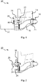
- FIGS. 1-5 show an embodiment of the thick matter conveying device 10 according to the invention, wherein different steps in the dismantling process of the transfer tube 18 from the thick matter collecting container 14 are shown.
- the drawings represent longitudinal sections through the diverter valve 18 and its bearings in the front wall 40 of the thick matter collection container 14 and on the conveyor line 16.
- An enlarged section of the front bearing 20 according to that in FIG figure 1 drawn circle is in the figure 6 to see.
- the transfer tube 18, which is designed as an S-tube, is used to alternately connect the delivery line 16 to one of two hydraulically driven delivery cylinders 12.
- the latter is preferably a feed hopper.
- the delivery cylinders 12 have cylinder openings at the ends facing the thick matter collection container 14 which cover corresponding suction openings in the front wall 40 . Through these suction openings, they alternately suck thick matter (e.g. concrete) out of the thick matter collection container 14 and press it through the transfer tube 18 into the delivery line 16 by means of a pump stroke.
- thick matter e.g. concrete
- the front end of the transfer tube 18 facing the delivery cylinders 12 is swiveled back and forth between the suction openings, so that the delivery cylinder 12 currently pumping is always connected to the delivery line 16, while the other delivery cylinder 12 sucks in thick matter through the free suction opening.
- the diverter valve 18 is rotatably fastened or mounted on the conveying line 16 via a rear bearing 21 .
- the connection of the diverter valve 18 to or in the rear bearing 21 can be detached in order to disassemble the diverter valve 18 .
- the diverter valve 18 is pivotally mounted in a front bearing 20.
- a shaft 22 is connected to the transfer tube 18 and is rotatably mounted in the front bearing 20 .
- the front bearing 20 is integrated into the front wall 40 and constructed as a two-piece bearing with two axially spaced bearing points 24, via which the shaft 22 is mounted.
- the shaft 22 has a pivoting lever 26 that protrudes radially on one side and is integral with the shaft 22, i.e. it is inseparably connected.
- the pivoting lever 26 At the end of the pivoting lever 26 are attached two hydraulic pivoting cylinders, not shown here, which are synchronized with the hydraulic drive of the delivery cylinders 12 in such a way that the previously described movement of the transfer tube 18 results.
- the front wall 40 of the thick matter collecting container 14 forms a frame structure with two side walls, between which the pivoting lever 26 and the pivoting cylinder are arranged. As a result, these components are optimal protected against contamination and damage typical for pump operation. Furthermore, the frame design results in a significantly lighter construction of the thick matter collection container 14 than when using a one-piece base plate with the same strength as the entire frame structure. Due to the two-part bearing of the shaft 22 via the two bearing points 24, which are each arranged above or in the area of one of the two side walls of the front wall 40, the forces or loads that occur are optimally absorbed and introduced into the front wall 40. The fully assembled state of the transfer tube 18 and the front bearing 20 is in the figure 1 shown, an enlarged view of the front bearing 20 is in FIG figure 6 to see.
- the front bearing 20 comprises a bearing part 30 firmly integrated into the front wall 40 (i.e. remaining) and a bearing part 28 that can be removed from the front wall 40, one of the bearing points 24 being arranged in/on one of the two bearing parts 28, 30.
- the removable bearing part 28 forms the end part of the front bearing 20 surrounding the shaft 22 at its end facing away from the transfer tube 18.
- the removable bearing part 28 can be detachably connected or locked to the front wall 40 and/or to the remaining bearing part 30.
- the shaft 22 has at the other end facing the diverter tube 18 radially circumferential toothing 32 which, in the installed state, engages in a corresponding toothing of a receptacle 34 which is arranged at the upper end of the diverter tube 18 and surrounds the end of the shaft 22 .
- a rotational movement of the shaft 22 is translated into a pivoting movement of the opening of the diverter valve 18 on the delivery cylinder side.
- the separable connection of the shaft 22 in the receptacle 34 of the transfer tube 18 can have an additional releasable connection or locking.
- the rear bearing 21 of the transfer tube 18 on the delivery line 16 is then released.
- the rear bearing 21 can remain on the transfer tube 18 or on the conveying line 16.
- the rear bearing 21 is constructed in several parts, with a part remaining on the transfer tube 18 and a part on the conveying line 16 . It can be provided here that the bearing or the part remaining on the conveying line 16 can be pushed backwards for the removal of the transfer tube 18 without being removed.
- the conveying line 16 also has a pivotable folding arch 36 . This is opened before the removal of the diverter tube 18 in order to relieve the diverter tube 18 .
- the diverter valve 18 can be removed from the sludge collector 14, as shown in FIG figure 5 you can see.
- the shaft 22 together with the pivoting lever 26 remain in the front bearing 20 or in the remaining bearing part 30.
- the diverter valve 18 is assembled in the reverse order.
- the removable bearing part 28 also serves to reinforce the frame construction of the front wall 40, so that additional reinforcements or clasps to absorb the tensile forces, as was previously necessary, are no longer necessary.
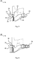
- the figure 7 shows the front bearing 20 of the diverter valve 18, designed as an S-tube, of a thick matter conveying device known from the prior art.
- the shaft 22 is firmly installed in the transfer tube 18 or connected to it and via a one-piece front bearing 20 in a solid base plate Front wall 40 of the sludge collection container 14 is mounted.
- a pivoting lever 26 is fastened to which the pivoting cylinders (not shown) are connected.
- the pivoted lever 26 is removed from the shaft 22, i.e. the point of separation between the diverter tube 18 and the pivoted lever 26 is outside of the thick matter collection tank 14.
- the shaft 22 must also be removed and laboriously threaded out of the front bearing 20 , which is difficult due to the massive or heavy construction of the transfer tube 18 .
- the rear bearing 21 of the transfer tube 18 must also be dismantled in a complex manner so that the shaft 22 can be unthreaded.
Landscapes
- Engineering & Computer Science (AREA)
- Mechanical Engineering (AREA)
- General Engineering & Computer Science (AREA)
- Refuse Collection And Transfer (AREA)
- Screw Conveyors (AREA)
Applications Claiming Priority (1)
| Application Number | Priority Date | Filing Date | Title |
|---|---|---|---|
| DE102020133021.9A DE102020133021A1 (de) | 2020-12-10 | 2020-12-10 | Dickstofffördervorrichtung |
Publications (2)
| Publication Number | Publication Date |
|---|---|
| EP4012176A1 true EP4012176A1 (fr) | 2022-06-15 |
| EP4012176B1 EP4012176B1 (fr) | 2025-12-31 |
Family
ID=78500405
Family Applications (1)
| Application Number | Title | Priority Date | Filing Date |
|---|---|---|---|
| EP21203291.6A Active EP4012176B1 (fr) | 2020-12-10 | 2021-10-18 | Dispositif de transport de matières épaisses |
Country Status (2)
| Country | Link |
|---|---|
| EP (1) | EP4012176B1 (fr) |
| DE (1) | DE102020133021A1 (fr) |
Citations (8)
| Publication number | Priority date | Publication date | Assignee | Title |
|---|---|---|---|---|
| DE2444464A1 (de) * | 1973-09-17 | 1975-03-27 | Case Co J I | Pumpvorrichtung zur foerderung von beton oder dergleichen plastischem material |
| DE2632816A1 (de) * | 1976-07-21 | 1978-01-26 | Schwing Gmbh F | Doppelzylinderpumpe, insbesondere fuer die foerderung von beton |
| DE2903749A1 (de) * | 1979-02-01 | 1980-08-14 | Schlecht Karl | Zweizylinder-pumpe mit hydrostatisch dichtender s-rohrweiche |
| DE2933128A1 (de) * | 1979-08-16 | 1981-02-26 | Schwing Gmbh F | Dickstoffpumpe, insbesondere zur foerderung von beton |
| GB1585794A (en) * | 1977-07-05 | 1981-03-11 | Relf D | Reciprocating pumps |
| US4298288A (en) * | 1980-01-25 | 1981-11-03 | Anthony Industries, Inc. | Mobile concreting apparatus and method |
| AU7811481A (en) * | 1980-11-28 | 1982-06-03 | H.A. Wentworth Pty Ltd | Swinging value for twin cylinder concrete pump |
| US20060124361A1 (en) * | 2004-07-27 | 2006-06-15 | David Mundell | Method of pumping drill cuttings and dual cylinder positive displacement pump for moving drill cuttings |
Family Cites Families (1)
| Publication number | Priority date | Publication date | Assignee | Title |
|---|---|---|---|---|
| DE2729159A1 (de) | 1977-06-28 | 1979-01-11 | Rotacrete Ltd | Kolbenpumpe |
-
2020
- 2020-12-10 DE DE102020133021.9A patent/DE102020133021A1/de active Pending
-
2021
- 2021-10-18 EP EP21203291.6A patent/EP4012176B1/fr active Active
Patent Citations (8)
| Publication number | Priority date | Publication date | Assignee | Title |
|---|---|---|---|---|
| DE2444464A1 (de) * | 1973-09-17 | 1975-03-27 | Case Co J I | Pumpvorrichtung zur foerderung von beton oder dergleichen plastischem material |
| DE2632816A1 (de) * | 1976-07-21 | 1978-01-26 | Schwing Gmbh F | Doppelzylinderpumpe, insbesondere fuer die foerderung von beton |
| GB1585794A (en) * | 1977-07-05 | 1981-03-11 | Relf D | Reciprocating pumps |
| DE2903749A1 (de) * | 1979-02-01 | 1980-08-14 | Schlecht Karl | Zweizylinder-pumpe mit hydrostatisch dichtender s-rohrweiche |
| DE2933128A1 (de) * | 1979-08-16 | 1981-02-26 | Schwing Gmbh F | Dickstoffpumpe, insbesondere zur foerderung von beton |
| US4298288A (en) * | 1980-01-25 | 1981-11-03 | Anthony Industries, Inc. | Mobile concreting apparatus and method |
| AU7811481A (en) * | 1980-11-28 | 1982-06-03 | H.A. Wentworth Pty Ltd | Swinging value for twin cylinder concrete pump |
| US20060124361A1 (en) * | 2004-07-27 | 2006-06-15 | David Mundell | Method of pumping drill cuttings and dual cylinder positive displacement pump for moving drill cuttings |
Also Published As
| Publication number | Publication date |
|---|---|
| EP4012176B1 (fr) | 2025-12-31 |
| DE102020133021A1 (de) | 2022-06-15 |
Similar Documents
| Publication | Publication Date | Title |
|---|---|---|
| DE102010037440A1 (de) | Exzenterschneckenpumpe | |
| DE202010018347U1 (de) | Kippbare Werkzeuganordnung | |
| DE2633718A1 (de) | Hydrostatisches getriebe | |
| DE102018102640A1 (de) | Exzenterschneckenpumpe | |
| DE102009037993B4 (de) | Exzenterschneckenpumpe | |
| EP1076596A1 (fr) | Conteneur delivreur de materiau, en particulier pour pompes a substances epaisses | |
| EP4012176B1 (fr) | Dispositif de transport de matières épaisses | |
| DE102013208101A1 (de) | Behälter zur Aufnahme von Dickstoffen | |
| EP1733146B1 (fr) | Conteneur destine au chargement de matieres pour pompe a matieres hautement visqueuses | |
| EP0209869A2 (fr) | Dispositif pour pivoter l'arbre d'un assemblage antidérapant à centrifuge de véhicules automobiles | |
| DE2944307A1 (de) | Muellpresse | |
| DE102018110917B4 (de) | Exzenterschneckenpumpe | |
| DE10242563B4 (de) | Schleuse für Schüttgut | |
| EP3337929B1 (fr) | Dispositif d'entraînement à filtrage en circulation | |
| DE102009036317A1 (de) | Vorrichtung zur Kanalreinigung | |
| DE3318312C2 (fr) | ||
| DE202010015437U1 (de) | Drehkolbenpumpe mit Hohlkolben | |
| EP3677351B1 (fr) | Bras de pendule pour un compresseur à rouleaux permettant de comprimer des déchets dans un conteneur ouvert | |
| EP4012180A1 (fr) | Dispositif de transport de matières épaisses comprenant un vibrateur | |
| EP4012181B1 (fr) | Dispositif de transport de matières épaisses | |
| EP4360762B1 (fr) | Dispositif de broyage | |
| EP4012178B1 (fr) | Dispositif de transport des matières épaisses et procédé de fonctionnement des dispositifs d'agitation d'un tel dispositif | |
| DE973688C (de) | Einrichtung zum Foerdern von Fetten oder anderen zaehen oder plastischen Stoffen auseinem Behaelter, z. B. einem Fass, mittels einer Fasspumpe od. dgl. | |
| DE102023115264A1 (de) | Vorrichtung und Verfahren zum Entleeren von körnigem Katalysatormaterial aus einem Reaktor | |
| DE60035295T2 (de) | Rotationspumpe |
Legal Events
| Date | Code | Title | Description |
|---|---|---|---|
| PUAI | Public reference made under article 153(3) epc to a published international application that has entered the european phase |
Free format text: ORIGINAL CODE: 0009012 |
|
| STAA | Information on the status of an ep patent application or granted ep patent |
Free format text: STATUS: THE APPLICATION HAS BEEN PUBLISHED |
|
| AK | Designated contracting states |
Kind code of ref document: A1 Designated state(s): AL AT BE BG CH CY CZ DE DK EE ES FI FR GB GR HR HU IE IS IT LI LT LU LV MC MK MT NL NO PL PT RO RS SE SI SK SM TR |
|
| STAA | Information on the status of an ep patent application or granted ep patent |
Free format text: STATUS: REQUEST FOR EXAMINATION WAS MADE |
|
| 17P | Request for examination filed |
Effective date: 20221209 |
|
| STAA | Information on the status of an ep patent application or granted ep patent |
Free format text: STATUS: EXAMINATION IS IN PROGRESS |
|
| 17Q | First examination report despatched |
Effective date: 20240215 |
|
| GRAP | Despatch of communication of intention to grant a patent |
Free format text: ORIGINAL CODE: EPIDOSNIGR1 |
|
| STAA | Information on the status of an ep patent application or granted ep patent |
Free format text: STATUS: GRANT OF PATENT IS INTENDED |
|
| INTG | Intention to grant announced |
Effective date: 20250904 |
|
| GRAS | Grant fee paid |
Free format text: ORIGINAL CODE: EPIDOSNIGR3 |
|
| GRAA | (expected) grant |
Free format text: ORIGINAL CODE: 0009210 |
|
| STAA | Information on the status of an ep patent application or granted ep patent |
Free format text: STATUS: THE PATENT HAS BEEN GRANTED |
|
| AK | Designated contracting states |
Kind code of ref document: B1 Designated state(s): AL AT BE BG CH CY CZ DE DK EE ES FI FR GB GR HR HU IE IS IT LI LT LU LV MC MK MT NL NO PL PT RO RS SE SI SK SM TR |
|
| REG | Reference to a national code |
Ref country code: CH Ref legal event code: F10 Free format text: ST27 STATUS EVENT CODE: U-0-0-F10-F00 (AS PROVIDED BY THE NATIONAL OFFICE) Effective date: 20251231 Ref country code: GB Ref legal event code: FG4D Free format text: NOT ENGLISH |
|
| REG | Reference to a national code |
Ref country code: DE Ref legal event code: R096 Ref document number: 502021009496 Country of ref document: DE |
|
| REG | Reference to a national code |
Ref country code: CH Ref legal event code: R17 Free format text: ST27 STATUS EVENT CODE: U-0-0-R10-R17 (AS PROVIDED BY THE NATIONAL OFFICE) Effective date: 20260126 |
|
| REG | Reference to a national code |
Ref country code: IE Ref legal event code: FG4D Free format text: LANGUAGE OF EP DOCUMENT: GERMAN |
|
| REG | Reference to a national code |
Ref country code: LT Ref legal event code: MG9D |
|
| PG25 | Lapsed in a contracting state [announced via postgrant information from national office to epo] |
Ref country code: NO Free format text: LAPSE BECAUSE OF FAILURE TO SUBMIT A TRANSLATION OF THE DESCRIPTION OR TO PAY THE FEE WITHIN THE PRESCRIBED TIME-LIMIT Effective date: 20260331 |
|
| PG25 | Lapsed in a contracting state [announced via postgrant information from national office to epo] |
Ref country code: FI Free format text: LAPSE BECAUSE OF FAILURE TO SUBMIT A TRANSLATION OF THE DESCRIPTION OR TO PAY THE FEE WITHIN THE PRESCRIBED TIME-LIMIT Effective date: 20251231 Ref country code: HR Free format text: LAPSE BECAUSE OF FAILURE TO SUBMIT A TRANSLATION OF THE DESCRIPTION OR TO PAY THE FEE WITHIN THE PRESCRIBED TIME-LIMIT Effective date: 20251231 |
|
| PG25 | Lapsed in a contracting state [announced via postgrant information from national office to epo] |
Ref country code: RS Free format text: LAPSE BECAUSE OF FAILURE TO SUBMIT A TRANSLATION OF THE DESCRIPTION OR TO PAY THE FEE WITHIN THE PRESCRIBED TIME-LIMIT Effective date: 20260331 |
|
| PG25 | Lapsed in a contracting state [announced via postgrant information from national office to epo] |
Ref country code: LV Free format text: LAPSE BECAUSE OF FAILURE TO SUBMIT A TRANSLATION OF THE DESCRIPTION OR TO PAY THE FEE WITHIN THE PRESCRIBED TIME-LIMIT Effective date: 20251231 |