EP4012182A1 - Pompe avec tête de pompe à raccord rapide et systèmes de surveillance et de commande de pompe - Google Patents
Pompe avec tête de pompe à raccord rapide et systèmes de surveillance et de commande de pompe Download PDFInfo
- Publication number
- EP4012182A1 EP4012182A1 EP21213543.8A EP21213543A EP4012182A1 EP 4012182 A1 EP4012182 A1 EP 4012182A1 EP 21213543 A EP21213543 A EP 21213543A EP 4012182 A1 EP4012182 A1 EP 4012182A1
- Authority
- EP
- European Patent Office
- Prior art keywords
- pump
- motor
- assembly
- head
- pump head
- Prior art date
- Legal status (The legal status is an assumption and is not a legal conclusion. Google has not performed a legal analysis and makes no representation as to the accuracy of the status listed.)
- Withdrawn
Links
- 238000012544 monitoring process Methods 0.000 title claims abstract description 38
- 238000012423 maintenance Methods 0.000 claims abstract description 23
- 230000008878 coupling Effects 0.000 claims abstract description 6
- 238000010168 coupling process Methods 0.000 claims abstract description 6
- 238000005859 coupling reaction Methods 0.000 claims abstract description 6
- 230000000295 complement effect Effects 0.000 claims description 21
- 238000007689 inspection Methods 0.000 claims description 16
- 239000012530 fluid Substances 0.000 claims description 15
- 238000004891 communication Methods 0.000 claims description 7
- 238000000034 method Methods 0.000 claims description 7
- 238000001816 cooling Methods 0.000 claims description 3
- 230000009471 action Effects 0.000 description 9
- 230000007246 mechanism Effects 0.000 description 8
- 230000008439 repair process Effects 0.000 description 8
- 238000005086 pumping Methods 0.000 description 7
- 230000000712 assembly Effects 0.000 description 5
- 238000000429 assembly Methods 0.000 description 5
- 230000001351 cycling effect Effects 0.000 description 3
- 230000007257 malfunction Effects 0.000 description 3
- 239000003086 colorant Substances 0.000 description 2
- 238000006073 displacement reaction Methods 0.000 description 2
- 238000005259 measurement Methods 0.000 description 2
- 238000012552 review Methods 0.000 description 2
- 239000007787 solid Substances 0.000 description 2
- 230000005477 standard model Effects 0.000 description 2
- 230000000007 visual effect Effects 0.000 description 2
- XLYOFNOQVPJJNP-UHFFFAOYSA-N water Substances O XLYOFNOQVPJJNP-UHFFFAOYSA-N 0.000 description 2
- 239000007844 bleaching agent Substances 0.000 description 1
- 230000008859 change Effects 0.000 description 1
- 238000010276 construction Methods 0.000 description 1
- 238000011109 contamination Methods 0.000 description 1
- 230000001934 delay Effects 0.000 description 1
- 238000001514 detection method Methods 0.000 description 1
- 230000000694 effects Effects 0.000 description 1
- 239000003337 fertilizer Substances 0.000 description 1
- 230000006870 function Effects 0.000 description 1
- 239000012528 membrane Substances 0.000 description 1
- 239000000575 pesticide Substances 0.000 description 1
- 238000000053 physical method Methods 0.000 description 1
- 230000004044 response Effects 0.000 description 1
Images





Classifications
-
- F—MECHANICAL ENGINEERING; LIGHTING; HEATING; WEAPONS; BLASTING
- F04—POSITIVE - DISPLACEMENT MACHINES FOR LIQUIDS; PUMPS FOR LIQUIDS OR ELASTIC FLUIDS
- F04B—POSITIVE-DISPLACEMENT MACHINES FOR LIQUIDS; PUMPS
- F04B51/00—Testing machines, pumps, or pumping installations
-
- F—MECHANICAL ENGINEERING; LIGHTING; HEATING; WEAPONS; BLASTING
- F04—POSITIVE - DISPLACEMENT MACHINES FOR LIQUIDS; PUMPS FOR LIQUIDS OR ELASTIC FLUIDS
- F04B—POSITIVE-DISPLACEMENT MACHINES FOR LIQUIDS; PUMPS
- F04B43/00—Machines, pumps, or pumping installations having flexible working members
- F04B43/02—Machines, pumps, or pumping installations having flexible working members having plate-like flexible members, e.g. diaphragms
-
- F—MECHANICAL ENGINEERING; LIGHTING; HEATING; WEAPONS; BLASTING
- F04—POSITIVE - DISPLACEMENT MACHINES FOR LIQUIDS; PUMPS FOR LIQUIDS OR ELASTIC FLUIDS
- F04B—POSITIVE-DISPLACEMENT MACHINES FOR LIQUIDS; PUMPS
- F04B35/00—Piston pumps specially adapted for elastic fluids and characterised by the driving means to their working members, or by combination with, or adaptation to, specific driving engines or motors, not otherwise provided for
- F04B35/04—Piston pumps specially adapted for elastic fluids and characterised by the driving means to their working members, or by combination with, or adaptation to, specific driving engines or motors, not otherwise provided for the means being electric
-
- F—MECHANICAL ENGINEERING; LIGHTING; HEATING; WEAPONS; BLASTING
- F04—POSITIVE - DISPLACEMENT MACHINES FOR LIQUIDS; PUMPS FOR LIQUIDS OR ELASTIC FLUIDS
- F04B—POSITIVE-DISPLACEMENT MACHINES FOR LIQUIDS; PUMPS
- F04B39/00—Component parts, details, or accessories, of pumps or pumping systems specially adapted for elastic fluids, not otherwise provided for in, or of interest apart from, groups F04B25/00 - F04B37/00
- F04B39/12—Casings; Cylinders; Cylinder heads; Fluid connections
- F04B39/121—Casings
-
- F—MECHANICAL ENGINEERING; LIGHTING; HEATING; WEAPONS; BLASTING
- F04—POSITIVE - DISPLACEMENT MACHINES FOR LIQUIDS; PUMPS FOR LIQUIDS OR ELASTIC FLUIDS
- F04B—POSITIVE-DISPLACEMENT MACHINES FOR LIQUIDS; PUMPS
- F04B39/00—Component parts, details, or accessories, of pumps or pumping systems specially adapted for elastic fluids, not otherwise provided for in, or of interest apart from, groups F04B25/00 - F04B37/00
- F04B39/12—Casings; Cylinders; Cylinder heads; Fluid connections
- F04B39/125—Cylinder heads
-
- F—MECHANICAL ENGINEERING; LIGHTING; HEATING; WEAPONS; BLASTING
- F04—POSITIVE - DISPLACEMENT MACHINES FOR LIQUIDS; PUMPS FOR LIQUIDS OR ELASTIC FLUIDS
- F04B—POSITIVE-DISPLACEMENT MACHINES FOR LIQUIDS; PUMPS
- F04B39/00—Component parts, details, or accessories, of pumps or pumping systems specially adapted for elastic fluids, not otherwise provided for in, or of interest apart from, groups F04B25/00 - F04B37/00
- F04B39/14—Provisions for readily assembling or disassembling
-
- F—MECHANICAL ENGINEERING; LIGHTING; HEATING; WEAPONS; BLASTING
- F04—POSITIVE - DISPLACEMENT MACHINES FOR LIQUIDS; PUMPS FOR LIQUIDS OR ELASTIC FLUIDS
- F04B—POSITIVE-DISPLACEMENT MACHINES FOR LIQUIDS; PUMPS
- F04B43/00—Machines, pumps, or pumping installations having flexible working members
- F04B43/02—Machines, pumps, or pumping installations having flexible working members having plate-like flexible members, e.g. diaphragms
- F04B43/04—Pumps having electric drive
-
- F—MECHANICAL ENGINEERING; LIGHTING; HEATING; WEAPONS; BLASTING
- F04—POSITIVE - DISPLACEMENT MACHINES FOR LIQUIDS; PUMPS FOR LIQUIDS OR ELASTIC FLUIDS
- F04B—POSITIVE-DISPLACEMENT MACHINES FOR LIQUIDS; PUMPS
- F04B53/00—Component parts, details or accessories not provided for in, or of interest apart from, groups F04B1/00 - F04B23/00 or F04B39/00 - F04B47/00
- F04B53/22—Arrangements for enabling ready assembly or disassembly
Definitions
- the present invention is directed to an improved pump and pump connection system, and in particular to a pump having a quick connect coupling between the pump head and the pump motor providing quick mounting and release of the pump to a mounting surface, and is also directed to a pump a controller and performance monitoring including sensors for detecting problems and possible failure.
- Positive displacement pumps and in particular diaphragm pumps are used for various applications. Depending upon the type of application, the pumps may need to be maintained or have components replaced. Many smaller diaphragm pumps include a pump head assembly that mounts to the motor. Rather than replacing the entire pump should the pump fail, during maintenance, it may be possible to simply replace the motor or the pump head.
- Such pumps may therefore fail without any warning to operators. It is also possible for inexperienced users to unknowingly operate the pumps in potentially damaging ways. Small diaphragm pumps are often used by turf/sprayer equipment operators, high end recreational vehicle owners, in agriculture, and construction equipment operators. These pumps are typically used outdoors and deal with a variety of working fluids including water, bleach, pesticides, and fertilizers. As downtime is critical, delays in determining when a pump fails can be very damaging and costly. When in a remote environment away from service technicians to replace the pumps or diagnose the issue, inexperienced users may conduct maintenance incorrectly and put the pump in to damaging operating conditions without knowing.
- a quick connect system for connecting a pump head to a pump motor assembly.
- Such a connection should provide for a quick engagement as well as quick decoupling of the components.
- Such a system should also eliminate the need for tools and loose retaining hardware.
- the connection and disconnection of the pump head to the pump motor is further improved if workers may simply use their hands to manually connect and disconnect the component assemblies.
- a quick connect mounting assembly of the pump to a surface without the need for tools or loose mounting hardware would further speed maintenance and provide for easier inspection and repair. Such mounting of the pump to a surface should be quickly and easily performed by a worker without the need for tools.
- Such a pump should further be configured so that the quick connect between the pump head and the motor and a quick release system for mounting the pump do not interfere with one another and may be actuated separately and independently.
- such pumps should provide for continuously monitoring performance and/or failure and providing information to operators to prevent pump failure.
- Such a system should be capable of sensing failure events, predicting the likelihood of failure events, monitoring the state of the pump head, and taking action to interrupt operation when a failure event occurs and indicate to the operator the status of the pumping system. In this way the operator can take appropriate action and conduct maintenance or repair activities before total system failure occurs.
- the present invention addresses these as well as other problems associated with pumps, coupling of pump components, and mounting of the pumps, as well as monitoring pump head operations, sensing failure events and reacting to such events to protect the pump from further damage.
- the present invention is directed to a pump with a quick connect coupling assembly for fast tool free inspection and maintenance.
- the present invention is also directed to a pump with a performance monitoring module.
- the pump may be a diaphragm pump with a head and a motor assembly including a motor with a drive shaft engaging and driving pumping components in the pump head.
- the pump head is coupled to the motor assembly by a hand actuatable quick disconnect assembly.
- the quick disconnect assembly is a bayonet type connector assembly including an adapter-type flange mounted to the pump head and a complementary to the motor assembly.
- the flange includes spaced apart radial engagement elements
- the receiver includes complementary L-shaped receiving slots configured to receive and retain the engagement elements.
- the motor assembly has a cylindrical housing and pump head has a complementary profile.
- the flange is circular with the engagement elements projecting radially inward and the receiver is configured as a collar and includes of complementary annularly extending L-shaped receiving slots configured to receive and retain the engagement elements upon relative rotation between the flange and the receiver.
- the quick connect assembly may include a locking pin for retaining the engagement elements in the receiving slots and therefore retaining the flange in engagement with the receiver.
- the pump further has a second quick connect assembly.
- the second quick connect assembly is a hand actuatable quick connect motor mounting assembly for mounting the pump to a mounting surface.
- the motor mounting assembly includes a cradle for receiving the motor assembly and a sliding retainer.
- the motor assembly has retaining screws extending radially outward with each of the retaining screws having a base and a screw head, and the sliding retainer engages the screw heads to secure the motor assembly to the quick connect motor mounting assembly.
- the pump is configured with the motor mounting assembly and the quick disconnect assembly positioned in an axially non-overlapping configuration so that the first and second quick connect assemblies do not interfere with one another.
- the advantageous mounting of the pump of the present invention provides for a method of maintaining a pump.
- the pump is inspected.
- the triggering event may be scheduled maintenance or a problem.
- the pump may include sensors that provide performance data and/or provide a signal or alarm that may trigger inspection.
- the head is removed from the motor assembly by manually decoupling the first quick disconnect assembly free of tools.
- the pump may be removed from the mounting surface, if needed, by manually decoupling the second quick disconnect.
- the quick connect assemblies are decoupled manually without the need for any tools.
- the motor and/or the pump head are inspected. Following inspection and any needed maintenance, the motor is remounted if it passes inspection.
- the motor fails inspection, the motor may be replaced with a different motor.
- the pump head passes inspection, the pump head may be recoupled to the motor assembly. If the pump head fails inspection, the pump head may be replaced with a different pump head. It is also possible that an entirely different pump may be needed, and the new pump is quickly mounted to the mounting surface without the need for tools.
- the pump includes a pump monitoring system that mounts to the pump and has a complementary shape with a surface configured to fit around the exterior of the generally cylindrical housing of the motor.
- the pump provides operational signals to an integrated control module that can monitor one or more parameters and trigger a predetermined response in the event a parameter enters a specific state or exceeds an acceptable operating range, as determined by the controller's programming.
- the monitoring system has a modular configuration that is self-contained and can therefore be easily adapted to fit onto standard models of pumps.
- the monitor housing may include radially and longitudinally extending cooling fins.
- the pump monitoring system includes a relay unit and a controller/processor gathering operational and performance information of the pump and providing output to operators.
- the controller/processor may be integrated on the pump to capture information that can be used to determine the life and performance of the pump and/or to determine whether maintenance should be performed.
- the boundary conditions that dictate when the control module reacts to an event correspond to the type of input signal and can be binary in nature (i.e. open/closed) or a continuous range (0 ⁇ value ⁇ 5).
- Different control actions may be used to respond to different sensing and triggering events. These actions can be classified in two distinct categories; 1) alarm actions that are intended to protect the pumping system such as termination of operation, and 2) warning actions to notify the operator important information that may impact the pumping system negatively but is not currently causing malfunction.
- control module measures input signals, compares the measurements to defined boundary conditions, and sends signals to additional components to execute control actions and store values in memory to create event history logs.
- the pump monitoring system protects the pump from further damage if failure begins and provides warnings for problems that are experienced in operation.
- the processor/controller is also able to establish operational settings at the factory and modify settings in the field after being placed in use.
- the relay unit connects to the controller/processor, a power source, such as AC, a solar energy panel or a battery, and to the pump.
- a moisture sensor includes a connector for mounting to the motor side of the pump for detecting fluid leaks to the motor. The connector and the sensor are preferably attached with a quick disconnect so that the elements may be easily switched or interchanged should a new motor or monitoring system be needed. In one embodiment, the relay unit will disconnect the pump in case of moisture detected by the moisture sensor.
- the controller/processor receives data and information from various sensors and/or inputs.
- the controller/processor also includes a data port and a wireless communication device.
- the data port and wireless communication device provide for outputting information to a central control system, to a PC or other mobile device.
- the inputs and sensors can be various types of sensors including flow meters, heat sensors, moisture sensors, timer, electrical sensors measuring current, resistance, and related electrical system variables, as well as other meters and sensors that measure parameters that indicate performance of the pump.
- the sensing signals include, but are not limited to, physical measurements such as temperature, current, voltage and operating time or discreet values such as on/off, open/closed, and high/low voltage.
- the pump monitoring system is configured to acquire data including, but not limited to outlet/system pressure, motor temperature, fluid temperature, diaphragm cavity temperature, flow rate, motor RPM, motor current, motor voltage, runtime, and vibration.
- the pump monitor system utilizes the information received by the processor and have the capability to control the pump and provide performance operation to operators.
- the pump monitoring is configurable to provide a variety of information, including, but not limited to:
- the controller/processor includes an exterior user interface that provides a display with an indication of the status of the pump's operations.
- the user interface includes status indicators to display a mode or current operational status of the pump.
- the user interface includes LED indicator lights such as a run light to indicate that the pump is in a normal operating condition, a service light to indicate that the pump requires maintenance and/or repairs, a failure light to indicate that the pump has failed and is not operating, and/or a diagnostic light to indicate that the pump is in a diagnostic mode.
- the indicator lights have different colors to provide a quick visual indication of the operational status of the pump.
- the interface provides for diagnosing problems and setting up operation of the pump.
- a small magnet is used to enter diagnostic mode and to reset the device, although a switch or other actuation could also be used depending on the application and site where the pump is operating.
- the magnet is held on the interface over the failure light.
- One or more of the lights or combinations of the light may blink and/or show solid to indicate start of reset and to indicate that the reset is complete.
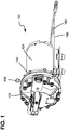
- the pump (100) is a diaphragm pump and includes a motor assembly (104) and a pump head (102). It can be appreciated that other types of pumps having a pump head connecting to a motor and driven by a motor are also foreseen according to the present invention.
- the motor assembly (104) includes an outer generally cylindrical housing, and the motor is typically an electrical motor and includes a cord or wiring (190).
- a drive shaft (106) extends from the motor and is driven by the electric motor (104) to engage and drive the pumping elements of the pump head (102).
- a first quick connect assembly (108) allows for simple and quick connection and disconnection of the pump head (102) to the motor assembly (104) without the use of any tools, as explained hereinafter.
- the ability for a worker to manually remove and mount the motor (104) and the pump head (102) to one another by hand without the need for tools provides for simple and quick maintenance.
- the ability to mount and remove without tools also allows for mounting in positions and locations that might be difficult to access if tools are needed to engage mounting hardware.
- the motor assembly (104) and the pump head assembly (102) may be quickly inspected and interchanged if there are problems so that down time for maintenance and repairs is substantially reduced with the quick connect assembly (108).
- the pump (100) also includes a second quick connect assembly (150) for mounting the pump to a mounting surface.
- the pump head (102) includes a pump head upper housing assembly (120) and a pump head lower housing assembly (122).
- the pump head upper housing assembly (120) generally retains the various valves and flow components.
- the pump (100) is a wobble plate type diaphragm pump including five chambers. It can be appreciated that other types of pumps or diaphragm pumps might be utilized. Moreover, such wobble plate type pumps may have a different number of chambers, such as three chambers.
- a molded diaphragm (130) mounts to the lower housing assembly (122) and includes five distinct portions that are engaged by valves in the head (102) as the wobble plate rotates, as is well known in the art.
- the pump head's major components are generally connected by a plurality of bolts (192).
- the upper housing assembly (120) of the pump head assembly (102) also includes a fluid inlet port (124) and a fluid outlet port (126).
- the inlet port (124) and the outlet port (126) may include mounting portions, such as threaded connections or other types of connections or adapters to mount to incoming and outgoing fluid lines.
- the pump (100) of the present invention completely contains the fluid to be pumped within the pump head (102) and fluid is kept out of the motor assembly (104).
- a receiving slot (132) receives the drive shaft (106) and provides for driving the valves and wobble plate and other components of the pump head to produce a pumping action.
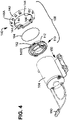
- the quick connect assembly (108) includes a quick connect receiver (110) that couples to a flange (140).
- the receiver, or collar, (110) mounts to an end of the motor assembly (104) against the outer housing of the motor assembly.
- the quick connect receiver (110) of the motor assembly (104) couples to the complementary quick connect flange (140) of the head (102) to removably couple the head (102) and the motor assembly (104).
- an O-ring type gasket (194) provides for a seal between the receiver (110) and the flange (140).
- the receiver (110) and the flange (140) are connected by a bayonet type engagement system.
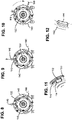
- the quick connect flange (140) includes a generally circular outer flange frame (142). Extending radially inward from the frame (142) are male engagement elements (144), as shown in greater detail in Figure 12 .
- the male engagement elements are shown as substantially rectangular and radially inward protruding raised portions, but other shapes are also foreseen.
- the quick connect frame (142) includes a pin receiving hole (148A). The hole (148A) receives a quick connect pin or other element that locks the flange (140) to the receiver (110), as explained hereinafter.
- the flange includes five engagement elements (144) spaced apart and protruding inward to engage five complementary slots of the receiver (110). However, a lesser number or greater number of engagement elements and complementary slots may also be utilized.
- the quick connect receiver (110) is configured to mount to the motor assembly (104) and is complementary to the flange (140).
- the receiver (110) includes L-shaped slots (112) spaced apart around a periphery of the receiver and configured to receive the complementary male engagement elements (144).
- the slots (112) are L-shaped slots, including a widened slot first arm portion (114) and a slot second arm portion (116) extending annularly from the first portion (114).
- the slots (112) and engagement elements (144) are complementary shaped and configured so that the engagement element (144) slides into the first arm portion (114) of the corresponding slot (114).
- the pump head (102) and motor assembly (104) are then rotated relative to one another, thereby also rotating the flange (140) relative to the receiver (110). This rotation moves the engagement elements (144) into the second arm portion (116) of the L-shaped slot (112).
- the engagement elements (144) and the second slot arm portion (116) have complementary angled surfaces, chamfered surfaces or other complementary portions that engage so that the receiver (110) and the flange (140) cannot be pulled axially apart.
- a locking pin (146) is utilized.
- the locking pin (146) may be spring-loaded or may be a threaded member, such as a thumbscrew type element.
- the locking pin extends through the hole (148A) of the flange (140) and into the hole (148B) of the receiver (110).
- the pin (146) When lowered as shown in Figure 13 , the pin (146) is engaged in a fully locked position. Depending on the configuration of the pin, it may be lifted upward, or if threaded, the pin (146) is rotated to raise the pin (146). In the position shown in Figure 14 , the pin (146) is raised, which unlocks the flange (140) and the receiver (110).
- the pin (146) may be moved to a locked out position and unlocked so that the pin (146) cannot accidentally re-engage. Therefore, when in such a position, the flange (140) and the receiver (110) may be easily rotated relative to one another and then separated.
- FIGS 8-10 The locking, unlocking, and decoupling and their relative positions are shown in Figures 8-10 .
- the pin (146) is lowered to engage both the hole (148A) and extend into the hole (148B). This engagement by the pin (146) prevents relative rotation between the flange (140) and the receiver (110).
- the pin (146) is lifted, as indicated by the arrow in Figure 9 , the flange (140) and the receiver (110) are unlocked and may be rotated relative to one another.
- the flange (140) may be rotated clockwise as shown in Figure 10 , relative to the receiver (110), thereby moving the engagement elements (144) along the slot (112) to the first arm portion (114) of the L-shaped slot (112).
- the flange (140) may be freely pulled away from the receiver (110). Remounting of the flange (140) to the receiver (110) is easily done by simply reversing the steps so that the engagement elements (144) are moved into the second slot portion (116) of the L-shaped slot (112) and engaged and the pin (146) is lowered to extend into hole (148B) of the receiver (110).
- the pump mounting assembly (150) is also a quick connect assembly that allows for easily removing the entire pump (100) from a mounting surface or to other components in a fluid system.
- the pump mounting assembly (150) includes a cradle (152) with lateral mounting portions (154) extending laterally outward from the cradle (152).
- the lateral mounting portions may include mounting holes for receiving hardware and mounting the cradle (152) to a surface.
- the cradle (152) has an arcing surface complementary to the outer cylindrical surface of the pump assembly (104).
- Retaining screws (118) include a head portion that extends into complementary keyhole shaped orifices (162) of the mounting assembly (150).
- the pump mounting assembly (150) also includes a sliding retainer (156) actuated by a retainer handle (158).
- a spring return mechanism (160) provides for maintaining the position of the sliding member (156) relative to the cradle in a locked position.
- the sliding retainer (156) includes a handle (158) at one end. It can be appreciated that the retainer handle (158) slides with the retainer (156) between a retaining position engaging the heads of the screws (118) and a free position in which the screws (118) are disengaged and may be freely lifted from the mounting assembly (150).
- the biasing force of the return mechanism (160) is overcome by pulling the handle (158) outward to a free position.
- the sliding retainer (156) is pulled outward by the handle (158) to the position shown in Figure 20 .
- the motor assembly (104) is then placed against the cradle (152) with the mounting screws (118) extending through orifices in the cradle and an enlarged portion of the keyhole shaped orifices (162) in the sliding retainer (156).
- the handle (158) is released, and the return mechanism (160) pulls the sliding retainer inward to the locked position shown in Figure 19 .
- quick connect mounting assembly (150) and the quick connect assembly (108) between the pump head (102) and the motor assembly (104) are configured so that they do not interfere with one another. Moreover, it can be appreciated that both mounting mechanisms can be engaged and disengaged manually by hand without the need for any tools. Furthermore, there are no loose screws, bolts, clips, or other retaining hardware that might be lost.
- the present invention also provides for a method of inspecting and maintaining pumps and easily interchanging or replacing the motor (104) and/or the pump head (102) without the need for tools.
- the pump head (102) and/or the motor assembly (104) may incorporate sensors that monitor the performance of the pump (100). Therefore, if problems are indicated, such sensors may detect a general problem with the pump (100) or might detect a problem with the pump head (102) or a problem with the pump motor (104). The sensor may generate a signal or alarm to indicate a performance problem and the need for inspection and possible maintenance.
- the pumps (100) might also be inspected regularly under a maintenance schedule.
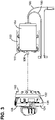
- the pump includes a pump monitoring system, generally designated (200).
- the pump monitoring system (200) includes a housing (202).
- the pump monitor housing (202) mounts to the pump (100) and has a complementary shape with an arcing surface (204) configured to fit around the exterior of the substantially cylindrical housing of the motor (104).
- the monitoring system (200) has a modular configuration that is self-contained and can therefore be easily adapted to fit onto standard models of pumps.
- the monitor housing (202) includes radially and longitudinally extending cooling fins (216).
- the pump monitoring system (200) includes a relay unit (210).
- the monitoring system (200) also includes a controller/processor (220) gathering operational and performance information of the pump (100) and providing output to operators.
- the controller/processor (220) is integrated on the pump (100) to capture information that can be used to determine the life and performance of the pump (100) and create a log and history.
- the controller/processor (220) protects the pump (100) from further damage if failure begins and provides warnings for performance issues that are experienced in operation, as explained hereinafter.
- the processor/controller (220) is also able to establish operational settings at the factory and modify the settings after being placed in use.
- the relay unit (210) connects to the controller/processor (220) through relay signal lines (208).
- the relay unit (210) also connects to a power source (300), such as the electrical grid, a solar energy panel or a battery through line (214).
- the relay unit (210) connect the pump (100) by a wiring line (212).
- the controller/processor (220) connects to the power source (300) by wiring (222) and associated ground (224).
- Sensors, such as a moisture sensor (206) includes a connector (226) for mounting to the motor side (104) of the pump (100) for detecting fluid leaks to the motor (104).
- the connector (226) and the sensor (206) are preferably coupled by a quick disconnect so that the elements may be easily switched or interchanged should a new motor (104) or monitoring system (200) be needed.
- the relay unit (210) will disconnect the pump (100) should moisture be detected by the moisture sensor (206).
- the controller/processor (220) receives data and information from various sensors and/or inputs (206, 240, 242, 244, 246, 248).
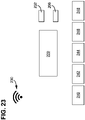
- the controller/processor (220) also includes a data port (232) and a wireless communication device (230).
- the wireless communication device (230) may be configured to use various types of wireless communication including, but not limited to, Wi-Fi, Bluetooth, CANNUD, and RF.
- the data port (232) and wireless communication device (230) provide for outputting information to a central control system, to a PC or other mobile device.
- the inputs and sensors (206, 240, 242, 244, 246, 248) can be various types of sensors including flow meters, heat sensors, moisture sensors, timer, electrical sensors measuring current, resistance, and related electrical system variables, as well as other meters and sensors that measure parameters that indicate performance of the pump (100).
- the pump monitoring system (200) is configured to acquire data for the following measurements:
- the pump monitor system (200) utilizes the information received by the processor and has the capability to control the pump (100) and provide performance operation information to operators.
- the pump monitor is configured to provide a variety of information, including, but not limited to:
- the controller/processor (220) includes an exterior user interface (250) having a display (hidden in Figure 21 ) that provides an indication of the status of the pump's operations.
- the user interface (250) includes a display with status indicators to show a mode or current operational status of the pump.
- the user interface (250) includes LED indicator lights.
- a run light (252) indicates that the pump is in a normal operating condition.
- a service light (254) indicates that the pump requires maintenance and/or repairs.
- a failure light (256) indicates that the pump has failed and is not operating.
- the failure indicator (256) may also include an associated audible alarm.
- a diagnostic light (258) indicates that the pump is in a diagnostic mode.
- the diagnostic mode is activated my placing a magnet (260) over the diagnostic light (258) that is sensed by the user interface (220).
- the indicator lights (252, 254, 256, 258) have different colors to provide a quick visual indication of the operational status of the pump.
- the interface (250) provides for diagnosing problems and setting up operation of the pump (100).
- the failure light (256) will turn ON while the water/contamination is in contact with the moisture sensor (206).
- the failure light (256) changes to flashing after the detection of moisture until the controller (220) is reset. This notifies the operator a leak was previously detected but not detected currently. Only when a leak is actively detected will the pump be OFF by the relay unit (210).
- the service light (254) will turn on when a predetermined time limit is exceeded, such as 400 hours.
- the magnet (260) is used to reset the device, although a switch or other actuation could also be used depending on the application and site where the pump is operating.
- the magnet is held on the interface (250) over the failure light (256).
- One or more of the lights (252, 254, 256, 258) or combinations of the light may blink and/or show solid to indicate start of reset and then change to indicate that the reset is complete.
- the controller/processor (220) and interface (250) provide for a diagnostic mode, which may be indicated by the diagnostic light (258).
- the magnet (260) is placed proximate the user interface, such as against the diagnostic indicator light (258) as shown in Figure 24 .
- a combination of flashing by one or more of the lights may indicate that the controller/processor (220) is in diagnostic mode.
- the magnet (260) may then be removed.
- the failure light (256) and the service light (254) may flash in particular patterns that may indicate the number of times the pump monitor system (200) has been reset and/or to indicate the total number of hours the pump has been operating.
- the pump monitoring system (200) is able to detect conditions that may require maintenance. When a triggering event such as scheduled maintenance or a problem are indicated by the monitoring system (200), the pump may be shut down by a switch, disconnecting the cord (190) or through the controller (220). The entire pump (100) may then be released from its mounting position by actuating the handle (158) of the pump mounting assembly (150) and lifting the pump (100) from the mounting assembly (150). Independently, the pump head (102) may also be simply removed by moving the locking pin (146) radially outward to disengage the hole (148B) and then rotating the pump head (102) relative to the motor (104) until the engagement elements (144) are moved to the first arm portion (114) of the L-shaped slot (112).
- the pump head (102) may then be simply pulled apart from the motor (104). It can also be appreciated that the drive shaft (106) is aligned with the complementary receiving slot and simply slides into and out of the slot (132) without the need for any tools or adapters. If the pump head (102) and the motor (104) are satisfactory following inspection, they may be simply be reassembled. However, if either the pump head (102) or the motor (104) needs replacement, these assemblies may be replaced and the replacement components are connected to one another, placed in the cradle (152), and mounted again to a mounting surface. Moreover, certain operational features of the controller (220) may be reset as appropriate. Reconnection of the cord (190) or actuation of a switch or the controller (220) would restart the pump (100).
Landscapes
- Engineering & Computer Science (AREA)
- Mechanical Engineering (AREA)
- General Engineering & Computer Science (AREA)
- Reciprocating Pumps (AREA)
- Control Of Positive-Displacement Pumps (AREA)
- Details Of Reciprocating Pumps (AREA)
Applications Claiming Priority (1)
| Application Number | Priority Date | Filing Date | Title |
|---|---|---|---|
| US202063123375P | 2020-12-09 | 2020-12-09 |
Publications (1)
| Publication Number | Publication Date |
|---|---|
| EP4012182A1 true EP4012182A1 (fr) | 2022-06-15 |
Family
ID=78829780
Family Applications (1)
| Application Number | Title | Priority Date | Filing Date |
|---|---|---|---|
| EP21213543.8A Withdrawn EP4012182A1 (fr) | 2020-12-09 | 2021-12-09 | Pompe avec tête de pompe à raccord rapide et systèmes de surveillance et de commande de pompe |
Country Status (3)
| Country | Link |
|---|---|
| US (1) | US20220178366A1 (fr) |
| EP (1) | EP4012182A1 (fr) |
| AU (1) | AU2021282453A1 (fr) |
Families Citing this family (6)
| Publication number | Priority date | Publication date | Assignee | Title |
|---|---|---|---|---|
| US12264669B2 (en) * | 2021-03-24 | 2025-04-01 | Farmchem Corp | Self-priming transfer pump with quick pump attachment/detachment |
| TWI784532B (zh) * | 2021-05-19 | 2022-11-21 | 周文三 | 空壓機裝置 |
| TWI778633B (zh) * | 2021-05-24 | 2022-09-21 | 周文三 | 空氣壓縮機裝置 |
| US12486841B2 (en) * | 2022-07-08 | 2025-12-02 | Blue-White Industries, Ltd. | Pivotable pump head |
| CN117469147A (zh) * | 2023-12-13 | 2024-01-30 | 台州信溢农业机械有限公司 | 用于泵体快速连接的接头结构 |
| CN119267205B (zh) * | 2024-09-20 | 2025-11-21 | 三峡金沙江云川水电开发有限公司 | 一种安装机构及推导外循环油泵自动控制系统 |
Citations (5)
| Publication number | Priority date | Publication date | Assignee | Title |
|---|---|---|---|---|
| EP2031250A1 (fr) * | 2007-08-28 | 2009-03-04 | Itt Manufacturing Enterprises, Inc. | Couplage par friction pour tête de pompe ajustable pour permettre une rotation de 360° |
| US20130129535A1 (en) * | 2010-08-04 | 2013-05-23 | Gunther Erich Schmid | Pump |
| CN105443351A (zh) * | 2015-12-28 | 2016-03-30 | 南通市希望电器有限公司 | 无螺丝快速组装式雾化压缩泵 |
| CN105673457A (zh) * | 2016-04-05 | 2016-06-15 | 东莞瑞柯电子科技股份有限公司 | 一种无螺钉充气泵机芯 |
| EP3167190A1 (fr) * | 2014-07-08 | 2017-05-17 | Flow Control LLC. | Procédé pour fixer des pompes à des moteurs électriques |
Family Cites Families (5)
| Publication number | Priority date | Publication date | Assignee | Title |
|---|---|---|---|---|
| US20060060685A1 (en) * | 2004-09-17 | 2006-03-23 | Crane Pumps | Grinder pump system |
| US10465676B2 (en) * | 2011-11-01 | 2019-11-05 | Pentair Water Pool And Spa, Inc. | Flow locking system and method |
| US9671270B2 (en) * | 2015-07-30 | 2017-06-06 | Daniel Measurement And Control, Inc. | Flow meter having electronic mount bracket assembly |
| GB2556574B (en) * | 2015-09-02 | 2021-10-20 | Halliburton Energy Services Inc | Variable frequency drive motor control |
| ITUA20163925A1 (it) * | 2016-05-30 | 2017-11-30 | Magneti Marelli Spa | Macchina elettrica ad architettura tangenziale con raffreddamento ad aria migliorato |
-
2021
- 2021-12-08 AU AU2021282453A patent/AU2021282453A1/en not_active Abandoned
- 2021-12-08 US US17/545,803 patent/US20220178366A1/en not_active Abandoned
- 2021-12-09 EP EP21213543.8A patent/EP4012182A1/fr not_active Withdrawn
Patent Citations (5)
| Publication number | Priority date | Publication date | Assignee | Title |
|---|---|---|---|---|
| EP2031250A1 (fr) * | 2007-08-28 | 2009-03-04 | Itt Manufacturing Enterprises, Inc. | Couplage par friction pour tête de pompe ajustable pour permettre une rotation de 360° |
| US20130129535A1 (en) * | 2010-08-04 | 2013-05-23 | Gunther Erich Schmid | Pump |
| EP3167190A1 (fr) * | 2014-07-08 | 2017-05-17 | Flow Control LLC. | Procédé pour fixer des pompes à des moteurs électriques |
| CN105443351A (zh) * | 2015-12-28 | 2016-03-30 | 南通市希望电器有限公司 | 无螺丝快速组装式雾化压缩泵 |
| CN105673457A (zh) * | 2016-04-05 | 2016-06-15 | 东莞瑞柯电子科技股份有限公司 | 一种无螺钉充气泵机芯 |
Also Published As
| Publication number | Publication date |
|---|---|
| AU2021282453A1 (en) | 2022-06-23 |
| US20220178366A1 (en) | 2022-06-09 |
Similar Documents
| Publication | Publication Date | Title |
|---|---|---|
| US20220178366A1 (en) | Pump with quick connect pump head and pump monitoring and control systems | |
| CN101443634B (zh) | 用于测量值传输的装置 | |
| US10024753B2 (en) | Sealing system having leakage sensing function | |
| US20240200552A1 (en) | Pump health monitoring system | |
| US20040128107A1 (en) | Heavy equipment having oil pollution degree diagnosing function, and oil pollution degree measuring system on network using the same, and operation method | |
| EP1869654A2 (fr) | Unite de commande pour vanne d'isolement d'urgence comprenant un indicateur d'anomalie incorpore | |
| US8437922B2 (en) | Systems and methods for detection of piston pump failures on mobile machines | |
| WO2019060478A1 (fr) | Système de filtre comprenant des diagnostics intégrés | |
| KR102051128B1 (ko) | 수중 펌프 상태 실시간 모니터링 시스템 및 방법 | |
| US8966967B2 (en) | System and method for determining a health of a bearing of a connecting rod | |
| KR20230007691A (ko) | 독립된 이상 신호 감지 db를 구비한 밸브 진단 감시장치 | |
| US20220373447A1 (en) | System for monitoring particle contamination in power pressure systems | |
| US7379825B2 (en) | Multifunctional electronic device for a mechanical seal and control and management process realised by such device | |
| CA3106039A1 (fr) | Systemes de commande et de regulation de gaz a distance et dispositifs associes | |
| JP4286649B2 (ja) | 建設機械のエンジン冷却水系統故障診断装置 | |
| KR20170142356A (ko) | Wcdma를 이용한 원격 고장진단모듈을 구비한 공기압축시스템 | |
| CN101408166A (zh) | 隔膜泵单向阀故障自动诊断方法及其所采用的装置 | |
| CN214698210U (zh) | 一种柴油机泵组 | |
| EP3669952B1 (fr) | Autodiagnostic d'arroseur | |
| KR102720312B1 (ko) | 펌프의 고장 감지가 가능한 펌프 제어 시스템 | |
| KR102406874B1 (ko) | 자가 진단이 가능한 자동제어장치 | |
| US12606994B2 (en) | Diagnostic system for monitoring a hydraulic system | |
| US12264995B2 (en) | Leak monitoring manifold for a pumping system | |
| CN112962541B (zh) | 一种液压启闭机运维智能服务平台 | |
| KR200364814Y1 (ko) | 센서 내장형 자동진단 밸브 |
Legal Events
| Date | Code | Title | Description |
|---|---|---|---|
| PUAI | Public reference made under article 153(3) epc to a published international application that has entered the european phase |
Free format text: ORIGINAL CODE: 0009012 |
|
| STAA | Information on the status of an ep patent application or granted ep patent |
Free format text: STATUS: THE APPLICATION HAS BEEN PUBLISHED |
|
| AK | Designated contracting states |
Kind code of ref document: A1 Designated state(s): AL AT BE BG CH CY CZ DE DK EE ES FI FR GB GR HR HU IE IS IT LI LT LU LV MC MK MT NL NO PL PT RO RS SE SI SK SM TR |
|
| STAA | Information on the status of an ep patent application or granted ep patent |
Free format text: STATUS: REQUEST FOR EXAMINATION WAS MADE |
|
| 17P | Request for examination filed |
Effective date: 20221215 |
|
| RBV | Designated contracting states (corrected) |
Designated state(s): AL AT BE BG CH CY CZ DE DK EE ES FI FR GB GR HR HU IE IS IT LI LT LU LV MC MK MT NL NO PL PT RO RS SE SI SK SM TR |
|
| GRAP | Despatch of communication of intention to grant a patent |
Free format text: ORIGINAL CODE: EPIDOSNIGR1 |
|
| STAA | Information on the status of an ep patent application or granted ep patent |
Free format text: STATUS: GRANT OF PATENT IS INTENDED |
|
| INTG | Intention to grant announced |
Effective date: 20231205 |
|
| GRAS | Grant fee paid |
Free format text: ORIGINAL CODE: EPIDOSNIGR3 |
|
| STAA | Information on the status of an ep patent application or granted ep patent |
Free format text: STATUS: THE APPLICATION IS DEEMED TO BE WITHDRAWN |
|
| 18D | Application deemed to be withdrawn |
Effective date: 20240702 |