EP4012347B1 - Système et procédé de mappage de l'environnement d'un véhicule - Google Patents
Système et procédé de mappage de l'environnement d'un véhicule Download PDFInfo
- Publication number
- EP4012347B1 EP4012347B1 EP20213858.2A EP20213858A EP4012347B1 EP 4012347 B1 EP4012347 B1 EP 4012347B1 EP 20213858 A EP20213858 A EP 20213858A EP 4012347 B1 EP4012347 B1 EP 4012347B1
- Authority
- EP
- European Patent Office
- Prior art keywords
- grid
- vehicle
- occupancy
- calculated
- values
- Prior art date
- Legal status (The legal status is an assumption and is not a legal conclusion. Google has not performed a legal analysis and makes no representation as to the accuracy of the status listed.)
- Active
Links
Images



Classifications
-
- G—PHYSICS
- G01—MEASURING; TESTING
- G01P—MEASURING LINEAR OR ANGULAR SPEED, ACCELERATION, DECELERATION, OR SHOCK; INDICATING PRESENCE, ABSENCE, OR DIRECTION, OF MOVEMENT
- G01P3/00—Measuring linear or angular speed; Measuring differences of linear or angular speeds
-
- G—PHYSICS
- G01—MEASURING; TESTING
- G01C—MEASURING DISTANCES, LEVELS OR BEARINGS; SURVEYING; NAVIGATION; GYROSCOPIC INSTRUMENTS; PHOTOGRAMMETRY OR VIDEOGRAMMETRY
- G01C21/00—Navigation; Navigational instruments not provided for in groups G01C1/00 - G01C19/00
- G01C21/26—Navigation; Navigational instruments not provided for in groups G01C1/00 - G01C19/00 specially adapted for navigation in a road network
- G01C21/28—Navigation; Navigational instruments not provided for in groups G01C1/00 - G01C19/00 specially adapted for navigation in a road network with correlation of data from several navigational instruments
-
- G—PHYSICS
- G01—MEASURING; TESTING
- G01S—RADIO DIRECTION-FINDING; RADIO NAVIGATION; DETERMINING DISTANCE OR VELOCITY BY USE OF RADIO WAVES; LOCATING OR PRESENCE-DETECTING BY USE OF THE REFLECTION OR RERADIATION OF RADIO WAVES; ANALOGOUS ARRANGEMENTS USING OTHER WAVES
- G01S17/00—Systems using the reflection or reradiation of electromagnetic waves other than radio waves, e.g. lidar systems
- G01S17/88—Lidar systems specially adapted for specific applications
- G01S17/93—Lidar systems specially adapted for specific applications for anti-collision purposes
- G01S17/931—Lidar systems specially adapted for specific applications for anti-collision purposes of land vehicles
-
- G—PHYSICS
- G01—MEASURING; TESTING
- G01C—MEASURING DISTANCES, LEVELS OR BEARINGS; SURVEYING; NAVIGATION; GYROSCOPIC INSTRUMENTS; PHOTOGRAMMETRY OR VIDEOGRAMMETRY
- G01C21/00—Navigation; Navigational instruments not provided for in groups G01C1/00 - G01C19/00
- G01C21/26—Navigation; Navigational instruments not provided for in groups G01C1/00 - G01C19/00 specially adapted for navigation in a road network
- G01C21/34—Route searching; Route guidance
- G01C21/36—Input/output arrangements for on-board computers
- G01C21/3602—Input other than that of destination using image analysis, e.g. detection of road signs, lanes, buildings, real preceding vehicles using a camera
-
- G—PHYSICS
- G01—MEASURING; TESTING
- G01S—RADIO DIRECTION-FINDING; RADIO NAVIGATION; DETERMINING DISTANCE OR VELOCITY BY USE OF RADIO WAVES; LOCATING OR PRESENCE-DETECTING BY USE OF THE REFLECTION OR RERADIATION OF RADIO WAVES; ANALOGOUS ARRANGEMENTS USING OTHER WAVES
- G01S17/00—Systems using the reflection or reradiation of electromagnetic waves other than radio waves, e.g. lidar systems
- G01S17/86—Combinations of lidar systems with systems other than lidar, radar or sonar, e.g. with direction finders
-
- G—PHYSICS
- G01—MEASURING; TESTING
- G01S—RADIO DIRECTION-FINDING; RADIO NAVIGATION; DETERMINING DISTANCE OR VELOCITY BY USE OF RADIO WAVES; LOCATING OR PRESENCE-DETECTING BY USE OF THE REFLECTION OR RERADIATION OF RADIO WAVES; ANALOGOUS ARRANGEMENTS USING OTHER WAVES
- G01S17/00—Systems using the reflection or reradiation of electromagnetic waves other than radio waves, e.g. lidar systems
- G01S17/88—Lidar systems specially adapted for specific applications
- G01S17/89—Lidar systems specially adapted for specific applications for mapping or imaging
- G01S17/894—Three-dimensional [3D] imaging with simultaneous measurement of time-of-flight at a two-dimensional [2D] array of receiver pixels, e.g. time-of-flight cameras or flash lidar
-
- G—PHYSICS
- G06—COMPUTING OR CALCULATING; COUNTING
- G06F—ELECTRIC DIGITAL DATA PROCESSING
- G06F18/00—Pattern recognition
- G06F18/20—Analysing
- G06F18/25—Fusion techniques
-
- G—PHYSICS
- G06—COMPUTING OR CALCULATING; COUNTING
- G06V—IMAGE OR VIDEO RECOGNITION OR UNDERSTANDING
- G06V10/00—Arrangements for image or video recognition or understanding
- G06V10/70—Arrangements for image or video recognition or understanding using pattern recognition or machine learning
- G06V10/84—Arrangements for image or video recognition or understanding using pattern recognition or machine learning using probabilistic graphical models from image or video features, e.g. Markov models or Bayesian networks
-
- G—PHYSICS
- G06—COMPUTING OR CALCULATING; COUNTING
- G06V—IMAGE OR VIDEO RECOGNITION OR UNDERSTANDING
- G06V20/00—Scenes; Scene-specific elements
- G06V20/50—Context or environment of the image
- G06V20/56—Context or environment of the image exterior to a vehicle by using sensors mounted on the vehicle
-
- G—PHYSICS
- G06—COMPUTING OR CALCULATING; COUNTING
- G06V—IMAGE OR VIDEO RECOGNITION OR UNDERSTANDING
- G06V20/00—Scenes; Scene-specific elements
- G06V20/50—Context or environment of the image
- G06V20/56—Context or environment of the image exterior to a vehicle by using sensors mounted on the vehicle
- G06V20/58—Recognition of moving objects or obstacles, e.g. vehicles or pedestrians; Recognition of traffic objects, e.g. traffic signs, traffic lights or roads
Definitions
- the present disclosure relates to a method for mapping a vehicle environment, in particular for generating a velocity map of absolute object velocities in the vehicle environment, and a computer program product and object tracking system for performing the same method.
- Manually operated vehicles such as cars are typically provided with one or more sensors to sense and map the environment around the vehicle to assist the driver in safe operation of the vehicle.
- the vehicle may be provided with a sensor system which is configured to detect static and moving objects in the vehicle's surroundings.
- the velocity of objects should be calculated relative to earth's frame of reference rather than the vehicle's frame of reference, in order to determine which objects are static (and therefore form part of the static environment through which the vehicle moves) and dynamic (and therefore also moving through the static environment).
- Sensor data from the vehicle is obtained in the vehicle's frame of reference and may be used to generate an occupancy grid describing the location of objects in the vehicle's surroundings.
- the vehicle may generally be moving relative to the earth, both static and dynamic objects may have a relative velocity in the sensor data.
- DE 10 2013 217486 A1 discloses a method for representing an environment of a vehicle in an occupancy grid, wherein data is recorded with at least one environment detection system and wherein a probably travelled course of the vehicle is determined on the basis of vehicle sensors.
- a search in the occupancy grid for occupied grid cells delimiting a free space is performed within a search window along the probably travelled course.
- US 2019/047439 A1 discloses an area occupancy determining device.
- the device includes a memory configured to store at least one occupancy grid of a predetermined region, and a processor.
- the processor is configured to generate the occupancy grid of the predetermined region.
- the occupancy grid includes a plurality of grid cells, each grid cell framed by respective grid cell frame lines. At least some of the grid cells are assigned an information about the occupancy of the region represented by the respective grid cell.
- the processor is further configured to dynamically update the occupancy grid, thereby successively generating a plurality of updated occupancy grids. Each updated occupancy grid is moved relative to the previous occupancy grid such that an origin coordinate of the updated occupancy grid is positioned on a contact point of grid cell frame lines of adjacent grid cells.
- a computer-implemented method for mapping a vehicle environment comprising: a) defining a first grid in the earth frame of reference having a first coordinate system; b) initialising a position of the vehicle in the first grid and a first set of cell occupancy values of the first grid; c) receiving sensor data of the surroundings of the vehicle from one or more sensors on the vehicle; d) updating the first grid with a second set of occupancy values calculated at least in part from the sensor data; and e) calculating one or more absolute velocities of one or more objects in the earth frame of reference from a change in cell occupancy values of the first grid
- the method may further comprise transforming the position coordinates of the one or more absolute velocities to a vehicle frame of reference, and optionally the one or more absolute velocities in the vehicle frame of reference may be displayed on a display device of the vehicle.
- the one or more absolute velocities may be calculated using a motion detection algorithm, wherein each iteration of the first grid is used as an image input to the motion detection algorithm, and wherein the motion detection algorithm is an optical flow algorithm.
- One or more object velocities may be calculated for one or more objects in a velocity map grid containing the vehicle and following the position of the vehicle, and a border defining the velocity map grid may be at least a predetermined distance from a border defining the first grid.
- the first grid When the vehicle moves to a position at or within a predetermined distance to the border of the first grid, the first grid may be repositioned in the earth frame of reference such that the vehicle is more than the predetermined distance from the border defining the first grid.
- the cells of the repositioned first grid may be initialised with occupancy values of the overlapping cells in the prior position of the first grid.
- the borders of the velocity map grid may be parallel to the borders of the first grid.
- the second set of occupancy values may be calculated at least in part from the first set of occupancy values, and optionally the second set of occupancy values may be calculated from a fusion of the first set occupancy values and a third set of occupancy values calculated from the received sensor data.
- the fusion may optionally be a Bayesian fusion.
- the method may comprise classifying an object as dynamic if the absolute velocity of the object is more than a predetermined threshold value, and otherwise classifying the object as static.
- a computer program comprising computer-readable instructions which, when executed by a processor, cause the process to execute a method according to the first aspect.
- an object tracking system for a vehicle configured to perform the method according to the first aspect.
- Fig. 1A shows a vehicle 10 equipped with a device 20 for mapping the environment of the vehicle 10 according to one or more embodiments of the present disclosure.
- the device 20 may have various components mounted on the vehicle 10 at different locations, but for the sake of simplicity the device 20 is depicted as a single component mounted on the vehicle.
- the device 20 includes one or more sensors for sensing objects and/or free space in the surroundings of the vehicle 10.
- the device 20 includes one or more radar sensors, lidar sensors, ultrasonic sensors and/or imaging sensors for detecting objects in the surroundings of the vehicle 10.
- the device 20 is an object tracking system which is configured to map the environment of the vehicle 10 according to the methods disclosed herein.
- the sensors are mounted on the vehicle 10 such that they are able to sense objects within a field of view F of the vehicle surroundings, and in particular to sense the distance to objects in a plurality of directions from the vehicle 10 in the field of view.
- sensors may be mounted at the front corners of the vehicle 10.
- the field of view is depicted as extending in the frontward direction of the vehicle 10, although the field of view could extend in any direction of the vehicle. Further, the field of view could be a partial view of the vehicle's 10 surroundings, or it could be an entire panoramic view of the surroundings. It will be appreciated that the number, position and orientation of the sensors of the device 20 can be selected to achieve the desired field of view.
- Fig. 1B shows a side and plan view of the vehicle coordinate system (VCS) of the vehicle 10, although it will be appreciated that other vehicle coordinate systems may be selected without departing from the scope of the disclosure.
- the VCS may be a right-handed axis system, being centred on the centre of the rear axle for the vehicle 10 in a normal, stationary state.
- the x-axis of the VCS aligns with the vehicle sprung weight centreline C, and the y-axis aligns with the axis of the rear-wheel axle A.
- Fig. 2 shows a schematic block diagram of a device 20 for mapping the environment of the vehicle 10 according to one or more embodiments.
- the device 20 includes one or more sensors 22, an acquisition unit 24, an occupancy mapping unit 26 and a determining unit 28.
- the one or more sensors may be a radar sensor including one or more radar antennas configured to emit radar signals, for example modulated radar signals, e.g. a Chirp-Signal.
- a signal may be acquired or detected at the one or more antennas 110 and is generally referred to as a return signal.
- the return signal(s) may result from a reflection of the emitted radar signal(s) on an obstacle.
- the one or more antennas may be provided individually or as an array of antennas, wherein at least one antenna of the one or more antennas emits the radar signal(s), and at least one antenna of the one or more antennas detects the return signal(s).
- the detected or acquired return signal(s) represents a variation of an amplitude/energy of an electromagnetic field over time.
- the one or more sensors may include one or more lidar or ultrasonic sensors, which are similarly configured to emit signals to the surroundings of the vehicle and to detect reflected signals from the surroundings of the vehicle and therefore detect objects in the surroundings.
- the one or more sensors may alternatively or additionally include a stereo camera, from which distance to an object within the field of view of the stereo camera can be determined via a stereo algorithm.
- the acquisitioning unit 24 is configured to acquire sensor data (e.g. range and range rate data) from the one or more sensors and compute the location of one or more objects in the vehicle's surroundings from the sensor data.
- the acquisitioning unit 24 may acquire the return signal (e.g. detected at the one or more antennas) and may apply an analogue-to-digital (A/D) conversion thereto.
- the acquisitioning unit 24 may convert a delay between emitting the signal(s) and detecting the return signal(s) into range data indicating the distance between an object and the vehicle 10, and the direction of the object is also calculated from the return signal(s) (e.g. from comparing multiple signals from different antennas).
- the delay, and thereby the range data may be acquired by correlating the return signal(s) with the emitted radar signal(s).
- the acquisitioning unit 24 may acquire image data from one or more stereo cameras and perform a stereo algorithm on the image data to calculate the distance to an object and the vehicle 10.
- the position of the sensors on the vehicle 10 may be calibrated in the VCS and the acquisitioning unit 24 may be configured to convert the range data to position coordinates in the VCS. If multiple different sensor types are used having overlapping fields of view, then the data may be combined (e.g. by averaging the detected range values for each sensor or similar) to determine the position of an object in a given direction.
- the vehicle may be any vehicle such as a lorry, a truck, a farming vehicle, a motorbike, a train, a bus, an aircraft, a drone, a boat, a ship or the like.
- the occupancy mapping unit 26 is configured to acquire the coordinates of the detected objects or free space calculated by the acquisitioning unit 24, and to calculate an occupancy grid in the earth frame of reference based on the data. More specifically, the occupancy mapping unit 26 includes a sensor model which takes the acquired detection data from the acquisitioning unit 24 as an input and generates an occupancy grid from the data (it will be appreciated that any sensor model may be used - for example any physical model, deterministic model or inverse sensor model). For example, the occupancy mapping unit 26 may receive a plurality of detections from the acquisitioning unit, each detection including a range value and an azimuth (indicating the distance and direction of the detected object or free space with respect to the vehicle). The detections may then be converted into a set of occupancy probabilities for cells in an occupancy grid.
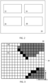
- the occupancy grid includes a grid of cells.
- the cell positions are defined using an occupancy grid coordinate system.
- the coordinate system may be a right-handed coordinate system, the origin being attached, for example at a corner of the grid.
- the coordinates of the bottom right cell is (0,0,0) with the coordinates of each neighbouring cell increasing by one in the direction of movement from the first cell.
- cell 34 has the coordinates (7,1) or (7,1,0) (the z value need not be included for a two-dimensional grid).
- the z-axis is defined in 2D applications to correctly define the direction of rotation, but may also be used to define the positions of cells in a 3D grid for 3D applications.
- the occupancy grid may be defined in an earth frame of reference, a vehicle frame of reference or another frame of reference.
- the occupancy grid may be generated in the vehicle frame of reference, and as such the coordinates of the occupancy grid each correspond to a fixed coordinate in the vehicle frame of reference.
- Each cell may take an occupancy value indicating whether that position is occupied by an object or not.
- the black cells 32 indicate that the cell is occupied by an object (and corresponds to the position where the sensors detect an object).
- the white cells 34 indicate that the cell is not occupied by an object.
- the grey cells 36 indicate that there is no knowledge of the occupancy of that cell (for instance because another object lies in between than cell and the sensors, such that no signal reaches the position corresponding to that cell.
- the occupancy value for each cell is calculated from the detections of the acquisitioning unit 24. For example, based on the range, azimuth and uncertainties of the detections, the occupancy evidence for each cell is calculated, which describes the probability that each cell is the origin of a detection (i.e. contains the location of the detection).
- the occupancy grid may be a Bayesian occupancy grid wherein the probability of the cell occupancy is calculated from evidence values obtained from the object and/or free space detections, although any type of occupancy grid may be used without departing from the present disclosure.
- the occupancy grid may include a grid of probabilities that each cell is occupied based on the P(occ) values and/or P(free) values.
- Each cell may then be assigned a probability value that the cell is occupied based on the object and/or free space detections.
- the occupancy grid may be rendered as, for example, a greyscale image or similar based on the probability value (0 being white/black, 1 being black/white), and as described in further detail below, a motion detection algorithm may be performed on the grayscale occupancy grid between time frames to detect object velocities.
- Each cell cell may instead be assigned as "occupied” if the occupancy probability is above an upper threshold, or "empty” if the occupancy probability is below a lower threshold.
- the occupancy grid may be rendered in two colours accordingly and an motion detection algorithm may be performed on the occupancy grid between time frames to detect object velocities. In some embodiments each grid cell may only be assigned "empty" or "occupied”.
- a cell may further be assigned as "unknown” if the occupancy probability is between the upper and lower threshold, when the thresholds differ. It will be appreciated that other methods may be used to generate the occupancy grid from the detection data. For example, a Dempster-Shafer framework may instead be used to generate the occupancy grid. Any suitable motion detection algorithm may be performed on the occupancy grid generated under any framework by measuring the change in the occupancy values of the occupancy grid between time frames.
- the device 20 includes a determining unit 28 for determining absolute object velocities in the earth frame of reference based on the occupancy grid data, by performing a motion detection algorithm on the occupancy grid.
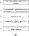
- Fig. 4 shows a flowchart of a method for mapping an environment of a vehicle, which may be performed, for example, by the device 20 on vehicle 10.
- a first grid is defined in the earth frame of reference, for example by mapping unit 26.
- the first grid defines a finite space.
- a position of the vehicle inside the first grid and a first set of cell occupancy values are both initialised.
- the initial position of the vehicle inside the first grid may be a predetermined position, preferably a position wherein the area around the vehicle that the vehicle sensors are configured to detect are contained within the first grid.
- the first set of cell occupancy values may be taken from previous sensor data already available to the device 20 (e.g. generated by mapping unit 26 from sensor data in a previous instance).
- the occupancy mapping unit 26 may generate an occupancy map in the coordinate system of the first grid, which can be calculated because the position of the vehicle in the first grid is known. If cell occupancy values are not readily available for all or part of the first grid, the cell occupancy values may be initialised to a default value (for example 0.5 is commonly used for a Bayesian grid, but other values may be taken).
- Fig. 5A shows a schematic diagram of the first grid 42 containing the vehicle 10.
- the first grid 42 is smaller than the area 40 which is sensed by the vehicle sensors, although in other embodiments this may not be the case.
- the occupancy values of the first grid 42 is omitted for simplicity but is analogous to that shown in Fig. 3 .
- the first grid 42 may have a larger, equal or smaller area than area 40, and preferably the first grid 42 is larger than the area 40.
- step S3 sensor data of the surroundings of the vehicle from one or more sensors on the vehicle is received (e.g. from sensors 22 by acquisition unit 24).
- Fig. 5B shows an exemplary schematic diagram of the vehicle 10 in a second position when the sensor data is received. It is noted that the device 20 may instead include no sensors, and sensor data may be obtained by a separate device on the vehicle and sent to the device 20 for processing according to the method of Fig. 4 .
- the first grid is updated with a second set of occupancy values calculated at least in part from the received sensor data, for example by occupancy mapping unit 26.
- the area 40 which is sensed by the vehicle moves with the vehicle 10 and so the sensor data is transformed back to the coordinate system of the first grid 42, which remains stationary relative to the earth. It may be that only some occupancy values are updated, as the area 40 which is sensed by the vehicle 10 in the new vehicle position does not cover the entire area of the first grid 42. Therefore, only the occupancy values in the overlapping area 48 of first grid 42 (shown as a patterned area) are updated, whereas the other occupancy values may be unchanged.
- the first grid may be updated by calculating a second occupancy grid from the sensor data and updating the first grid with the second set of occupancy values.
- the raw sensor data received by acquisition unit 24 is in the vehicle frame of reference, and the vehicle may have moved from and/or rotated about the initialised vehicle position in the first grid. Therefore, the data may be transformed from the vehicle coordinate system to the first coordinate system. This transformation may be performed on the sensor data by the occupancy mapping unit 26 before the second set of occupancy of values is generated, or an occupancy grid may be generated in the vehicle coordinate system and then transformed to the first coordinate system.
- the position of the vehicle in the first grid may be tracked, for example, by various vehicle systems, such as a GPS system and speed and turn measuring systems of the vehicle, such that the new position and orientation of the vehicle in relation to the initialised position is tracked by the occupancy mapping unit 26.
- the updated occupancy values of the first grid may be based partially on the previous occupancy values of the first grid and partially on the second set of occupancy values.
- the first grid may be updated by fusing the previous occupancy evidence values or the occupancy probability values of the first grid in the overlapping area 48 with a second set of occupancy evidence values or occupancy probability values calculated from the sensor data, for example by using a Bayesian fusion method.
- P old is the previous occupancy evidence or probability value for the cell
- P measured is the occupancy evidence or probability value for the cell calculated from the new sensor data.
- other fusion methods may be used instead of a Bayesian fusion method, such as maximum policy, sum policy, instant fusion, Linear Opinion Pool, Independent Opinion Pool, Logarithmic Independent Opinion Pool, De Morgan, Dempster Shafer, Dezert-Smarandache and the like. If no new measurements are received for a cell, the cell may take the same occupancy value. It is also noted that the occupancy grid may instead be directly updated with the new occupancy values (i.e. without any data fusion) without departing from the scope of the present disclosure.
- step S5 one or more absolute velocities of one or more objects in the earth frame of reference is generated from the change in cell occupancy values of the first grid (for example by determining unit 28, by comparing the occupancy values of the grid in different frames).
- the absolute velocities can be obtained directly from the change in occupancy values of the first grid.
- Figs. 5A and 5B show a velocity map grid 44 inside which the object velocities may be calculated (although they may be calculated over the entire grid 42, and grid 44 may be any size relative to grid 42). The velocities may be calculated for all of the objects detected in a given area (e.g. 44 or 42).
- Steps S3 to S5 may be performed iteratively as new sensor data is received, with the object velocities updating with each iteration based on the change in occupancy values of the first grid.
- the sensor measurements for each iteration may be separated in time by any time period, for example 0.1 seconds.
- the absolute velocities can be calculated using any motion detection algorithm such as any optical flow algorithm, e.g. locally regularized and vectorized algorithms, Lucas-Kanade algorithm or video motion detection and tracking algorithms or the like. Each iteration of the first grid is used as an image input to the motion detection algorithm.
- the method may include applying an object identification algorithm such as a clustering algorithm to classify groups of occupied cells as objects, and the optical flow algorithm may be applied to each object to estimate the velocity of the object (for example by averaging the velocity of each cell in the object or by an object tracking algorithm).
- the above method advantageously allows for a free choice of occupancy grid algorithms and of motion detection algorithms to determine absolute object velocities.
- the method updates an occupancy grid in the earth frame of reference using sensor data received in the vehicle's frame of reference, which process automatically disregards static objects in the environment.
- This allows absolute velocities to be computed directly from the occupancy grid (in contrast, performing a motion detection algorithm in the vehicle frame of reference requires additional complexity to differentiate between moving and static objects, both of which may appear to be moving or stationary in the vehicle frame of reference).
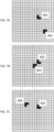
- Figs. 6A to 6C show an occupancy grid which is generated in a vehicle frame of reference at three different time instances. Occupied cells are shown as black and free cells are shown as white. A static object 602 appears to be moving in the occupancy grid relative to the vehicle, whereas a moving object 604 does not appear to be moving as it has a similar velocity to the vehicle.
- Figs. 7A to 7C show each respective frame of Figs. 6A to 6C when transformed to the earth frame of reference (i.e. on the first grid). This can be calculated because the position of the vehicle is initialised in the first grid and the movement of the vehicle from the initial position is tracked.
- an occupancy grid generated in the vehicle frame of reference can be readily transformed to the earth frame of reference, and the first grid can be updated with the new occupancy data.
- Figs. 7A to 7C it can be seen that the static object 602 remains static and the moving object 604 moves in the grid.
- any motion detection algorithm can be performed on the frames shown in Figs. 7A to 7C to directly detect the speed of an object relative to earth (for example moving object 604).
- This velocity relative to the earth may be displayed on a display device in the vehicle in the vehicle frame of reference, so that the driver may see which objects in the surroundings are moving in absolute terms.
- the method may include a further step of transforming the position coordinates of the one or more absolute velocities to a vehicle frame of reference.
- vehicle systems such as a GPS system
- the one or more absolute velocities is readily transformable to the vehicle frame of reference (it is noted that the velocities themselves are not transformed to the vehicle frame of reference).
- this may allow any object tracking system of the vehicle to identify dynamic (non-static) objects in the surroundings of the vehicle.
- the vehicle may include an advanced driver assistance system configured to predict the movement of dynamic objects (such as other vehicles) in the vicinity of the vehicle, in order to assist the driver in avoiding a collision.
- the absolute velocities may also be displayed on a display device of the vehicle. The display device may assist the driver of the vehicle in differentiating dynamic objects from static objects in the surroundings of the vehicle.
- the method may further include generating a third set of cell occupancy values from the sensor data; transforming the third set of cell occupancy values to the first coordinate system; updating the first grid with the third set of occupancy values; and calculating updated object velocities from the change in cell occupancy values of the first grid.
- the first grid may be updated iteratively as the vehicle moves around the environment, and the object velocities updated accordingly.
- Fig. 5C shows a schematic diagram of the vehicle in a third position.
- the area 40 which is sensed by the vehicle again moves in the vehicle's frame of reference and so the sensor data is transformed back to the coordinate system of the first grid 42, which remains stationary relative to the earth.
- the area 48 defining the overlap between the area 40 sensed by the vehicle 10 and the first grid 42 is updated with new occupancy values. Accordingly, a motion detection algorithm can be performed on the first grid to find the updated absolute velocities.
- the one or more object velocities are preferably calculated for a velocity map grid 44 velocity map following the position of the vehicle, as shown in Figs. 5A to 5C (i.e. the position coordinates of the vehicle, or the origin of the VCS, in the velocity map is constant), so that the object velocities are always generated for the same surrounding area of the vehicle.
- the border of the velocity map grid 44 may be at least a predetermined distance from the border defining the first grid 42. This predetermined distance ensures that the velocity map can reliably calculate object velocities at the edge of the velocity map grid 44, by ensuring buffer zones 46 are contained in the first grid 42 and therefore have occupancy values in each frame.
- an object which, between frames, moves into velocity map grid 44 from the buffer zones 46 may not be taken account of if the velocity map grid 44 is allowed to abut the first grid 42, as shown in Fig. 5D , because the buffer areas 46 are outside of the first grid 42 and thus do not have occupancy values assigned to them.
- the first grid 42 may be repositioned in the earth frame of reference such that the border defining the velocity map grid 44 is more than the predetermined distance from the border defining the first grid 42.
- Fig. 5E shows a schematic diagram of the vehicle 10 when the velocity map grid 44 is at a predetermined distance to the first grid in the original position 42a.
- the first grid is repositioned to a second position 42b further away from the velocity map grid 44 (i.e. at least partially in the direction of movement of the vehicle 10) so that further movement of the vehicle 10 in the direction is possible without the buffer zones 46 extending outside of the first grid 42.
- the vehicle position in the repositioned first grid may be initialised so that movement within the first grid is tracked to determine the position of the vehicle at any time.
- the borders of the velocity map grid 44 are maintained parallel to the borders of the first grid 42, regardless of the orientation of the vehicle 10 (i.e. the orientation of the VCS) relative to the earth frame of reference. This minimised the frequency that the first grid 42 must be shifted to maintain a minimum distance between the border of the velocity map grid 44 and the first grid 42.
- the borders of the velocity map grid 44 may not be parallel to the borders of the first grid 42, and the velocity map grid 44 may take any shaped.
- the velocity map grid 44 may also follow both the position and orientation of the vehicle 10 so that it may both translate and rotate relative to the first grid 42.
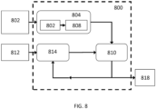
- the mapping unit 800 is further configured to receive a vehicle position measurement 812 and includes a positioning module 814 to calculate the position of the vehicle in the first grid coordinate system.
- P old is the previous occupancy evidence value for the cell
- P measured is the occupancy evidence value for the cell calculated from the new sensor data. It will be appreciated that other fusion methods may be used instead of a Bayesian fusion method.
- Some embodiments include a computer program product.
- the computer program product may be a storage medium or media, instruction store(s), or storage device(s), having instructions stored thereon or therein which can be used to control, or cause, a computer or computer processor to perform any of the procedures of the example embodiments described herein.
- the storage medium/instruction store/storage device may include, by example and without limitation, an optical disc, a ROM, a RAM, an EPROM, an EEPROM, a DRAM, a VRAM, a flash memory, a flash card, a magnetic card, an optical card, nanosystems, a molecular memory integrated circuit, a RAID, remote data storage/archive/warehousing, and/or any other type of device suitable for storing instructions and/or data.
- some implementations include software for controlling both the hardware of the system and for enabling the system or microprocessor to interact with a human user or other mechanism utilizing the results of the embodiments described herein.
- Such software may include without limitation device drivers, operating systems, and user applications.
- Such computer-readable media or storage device(s) further include software for performing example aspects, as described above.
- a module includes software, although in other example embodiments herein, a module includes hardware, or a combination of hardware and software.
Landscapes
- Engineering & Computer Science (AREA)
- Physics & Mathematics (AREA)
- General Physics & Mathematics (AREA)
- Remote Sensing (AREA)
- Radar, Positioning & Navigation (AREA)
- Theoretical Computer Science (AREA)
- Multimedia (AREA)
- Software Systems (AREA)
- Computer Vision & Pattern Recognition (AREA)
- Electromagnetism (AREA)
- Computer Networks & Wireless Communication (AREA)
- Evolutionary Computation (AREA)
- Artificial Intelligence (AREA)
- Medical Informatics (AREA)
- Health & Medical Sciences (AREA)
- General Health & Medical Sciences (AREA)
- Databases & Information Systems (AREA)
- Computing Systems (AREA)
- Probability & Statistics with Applications (AREA)
- Data Mining & Analysis (AREA)
- Automation & Control Theory (AREA)
- Life Sciences & Earth Sciences (AREA)
- Bioinformatics & Cheminformatics (AREA)
- Bioinformatics & Computational Biology (AREA)
- Evolutionary Biology (AREA)
- General Engineering & Computer Science (AREA)
- Traffic Control Systems (AREA)
Claims (12)
- Un procédé implémenté par calculateur pour la cartographie d'un environnement de véhicule, le procédé comprenant :a) la définition (S1) d'une première grille (42) dans le repère de référence terrestre avec un premier système de coordonnées ;b) l'initialisation (S2) d'une position du véhicule (10) dans la première grille (42) et d'un premier ensemble de valeurs d'occupation de cellule de la première grille (42) ;c) la réception (S3) de données de capteur des environs du véhicule (10), en provenance d'un ou plusieurs capteurs (22) sur le véhicule (10) ;d) la mise à jour (S4) de la première grille (42) avec un second ensemble de valeurs d'occupation calculées au moins en partie à partir des données de capteur ; ete) le calcul (S5) d'une ou plusieurs vitesses absolues d'un ou plusieurs objets (602, 504) dans le repère de référence terrestre, à partir d'une modification des valeurs d'occupation de cellule de la première grille (42).
- Le procédé de la revendication 1, comprenant en outre la transformation des coordonnées de position des une ou plusieurs vitesses absolues vers un repère de référence du véhicule, éventuellement dans lequel les une ou plusieurs vitesses absolues dans le repère de référence du véhicule sont affichées sur un dispositif afficheur du véhicule (10).
- Le procédé de la revendication précédente, dans lequel les étapes d) à e) sont répétées de manière itérative.
- Le procédé de la revendication 3, dans lequel les une ou plusieurs vitesses sont calculées à l'aide d'un algorithme de détection de mouvements dans lequel chaque itération de la première grille (42) est utilisée comme entrée d'image pour l'algorithme de détection de mouvements, l'algorithme de détection de mouvements étant un algorithme à flux optique.
- Le procédé de l'une des revendications précédentes, dans lequel les une ou plusieurs vitesses d'objets sont calculées pour un ou plusieurs objets (602, 504) dans une grille de cartographie des vitesses (44) contenant le véhicule (10) et suivant la position du véhicule (10), et dans lequel une frontière définissant la grille de cartographie des vitesses (44) est à au moins une distance prédéterminée par rapport à une frontière définissant la première grille (42).
- Le procédé de l'une des revendications précédentes, dans lequel, lorsque le véhicule (10) se déplace vers une position située à, ou dans les limites de, une distance prédéterminée de la frontière de la première grille (42), la première grille (42) est repositionnée dans le repère de référence terrestre de telle manière que le véhicule (10) se trouve à plus que la distance prédéterminée de la frontière définissant la première grille (42).
- Le procédé de la revendication 6, dans lequel les cellules de la première grille repositionnée (42) sont initialisées par des valeurs d'occupation des cellules chevauchantes dans la position antérieure de la première grille (42).
- Le procédé de l'une des revendications 5 à 7, dans lequel les frontières de la grille de cartographie des vitesses (44) sont parallèles aux frontières de la première grille (42).
- Le procédé de l'une des revendications précédentes, dans lequel le second ensemble de valeurs d'occupation est calculé au moins en partie d'après le premier ensemble de valeurs d'occupation, éventuellement dans lequel le second ensemble de valeurs d'occupation est calculé à partir d'une fusion du premier ensemble de valeurs d'occupation et d'un troisième ensemble de valeurs d'occupation calculées à partir des données de capteur reçues, la fusion étant éventuellement une fusion bayésienne.
- Le procédé de l'une des revendications précédentes, comprenant la classification d'un objet (602, 504) comme étant dynamique si la vitesse absolue de l'objet (602, 504) est supérieure à une valeur seuil prédéterminée, et dans le cas contraire la classification de l'objet (602, 504) comme étant statique.
- Un programme de calculateur comprenant des instructions lisibles par calculateur qui, lorsqu'elles sont exécutées par un processeur, font en sorte que le processeur exécute un procédé selon l'une des revendications précédentes.
- Un système de poursuite d'objets pour un véhicule (10), configuré pour mettre en œuvre le procédé selon l'une des revendications 1 à 10.
Priority Applications (3)
| Application Number | Priority Date | Filing Date | Title |
|---|---|---|---|
| EP20213858.2A EP4012347B1 (fr) | 2020-12-14 | 2020-12-14 | Système et procédé de mappage de l'environnement d'un véhicule |
| CN202111462842.5A CN114624460B (zh) | 2020-12-14 | 2021-12-02 | 用于映射载具环境的系统和方法 |
| US17/644,046 US12442928B2 (en) | 2020-12-14 | 2021-12-13 | System and method for mapping a vehicle environment |
Applications Claiming Priority (1)
| Application Number | Priority Date | Filing Date | Title |
|---|---|---|---|
| EP20213858.2A EP4012347B1 (fr) | 2020-12-14 | 2020-12-14 | Système et procédé de mappage de l'environnement d'un véhicule |
Publications (2)
| Publication Number | Publication Date |
|---|---|
| EP4012347A1 EP4012347A1 (fr) | 2022-06-15 |
| EP4012347B1 true EP4012347B1 (fr) | 2025-01-29 |
Family
ID=73835476
Family Applications (1)
| Application Number | Title | Priority Date | Filing Date |
|---|---|---|---|
| EP20213858.2A Active EP4012347B1 (fr) | 2020-12-14 | 2020-12-14 | Système et procédé de mappage de l'environnement d'un véhicule |
Country Status (3)
| Country | Link |
|---|---|
| US (1) | US12442928B2 (fr) |
| EP (1) | EP4012347B1 (fr) |
| CN (1) | CN114624460B (fr) |
Families Citing this family (5)
| Publication number | Priority date | Publication date | Assignee | Title |
|---|---|---|---|---|
| FR3140699B1 (fr) * | 2022-10-05 | 2024-08-23 | Psa Automobiles Sa | Procédé et dispositif de suivi de l’environnement d’un véhicule |
| GB2625735B (en) * | 2022-12-22 | 2025-05-28 | Jaguar Land Rover Ltd | Apparatus and method for determining a representation of an environment |
| GB2625733B (en) * | 2022-12-22 | 2025-06-11 | Jaguar Land Rover Ltd | Apparatus and method for determining a representation of an environment |
| CN116188517B (zh) * | 2023-01-19 | 2026-03-31 | 北京欣奕华科技有限公司 | 一种确定目标物体的场景变化率的方法、装置及介质 |
| EP4564308A1 (fr) * | 2023-11-30 | 2025-06-04 | Aptiv Technologies AG | Procédé et système de suivi d'un objet dans un champ de vision d'un véhicule hôte |
Family Cites Families (28)
| Publication number | Priority date | Publication date | Assignee | Title |
|---|---|---|---|---|
| US11209833B2 (en) * | 2004-07-07 | 2021-12-28 | Irobot Corporation | Celestial navigation system for an autonomous vehicle |
| US8558883B2 (en) * | 2007-07-27 | 2013-10-15 | Sportvision, Inc. | Providing graphics in images depicting aerodynamic flows and forces |
| JP5206752B2 (ja) * | 2010-08-30 | 2013-06-12 | 株式会社デンソー | 走行環境認識装置 |
| DE102013217486B4 (de) * | 2013-09-03 | 2026-03-19 | Aumovio Autonomous Mobility Germany Gmbh | Verfahren zur Repräsentation eines Umfelds eines Fahrzeugs in einem Belegungsgitter |
| DE102014208009A1 (de) | 2014-04-29 | 2015-10-29 | Bayerische Motoren Werke Aktiengesellschaft | Erfassen von statischen und dynamischen Objekten |
| CN106571046B (zh) * | 2016-11-11 | 2021-07-16 | 上海市政工程设计研究总院(集团)有限公司 | 基于路面网格体系的车路协同辅助驾驶方法 |
| CN108268483A (zh) * | 2016-12-30 | 2018-07-10 | 乐视汽车(北京)有限公司 | 生成用于无人车导航控制的网格地图的方法 |
| DE102017206436A1 (de) | 2017-04-13 | 2018-10-18 | Bayerische Motoren Werke Aktiengesellschaft | Verfahren zur Erkennung und/oder Verfolgung von Objekten |
| US10552979B2 (en) | 2017-09-13 | 2020-02-04 | TuSimple | Output of a neural network method for deep odometry assisted by static scene optical flow |
| DE102017216775A1 (de) * | 2017-09-21 | 2019-03-21 | Volkswagen Aktiengesellschaft | Verfahren, Vorrichtung und computerlesbares Speichermedium mit Instruktionen zur Steuerung einer Anzeige einer Augmented-Reality-Head-Up-Display-Vorrichtung für ein Kraftfahrzeug |
| DE112017008137T5 (de) * | 2017-10-03 | 2020-07-02 | Intel Corporation | Kartieren einer rasterbelegung unter verwendung einer fehlerbereichsverteilung |
| US11077756B2 (en) * | 2017-11-23 | 2021-08-03 | Intel Corporation | Area occupancy determining device |
| US20200020239A1 (en) * | 2018-07-13 | 2020-01-16 | Honeywell International Inc. | Characteristics of graphical icons for presentation of traffic information |
| US10914813B2 (en) * | 2018-08-21 | 2021-02-09 | Aptiv Technologies Limited | Classifying potentially stationary objects tracked by radar |
| CN112930554B (zh) * | 2018-09-12 | 2025-03-14 | 丰田自动车株式会社 | 用于确定车辆环境的语义网格的电子设备、系统和方法 |
| DE112019004698T5 (de) * | 2018-09-20 | 2021-06-24 | Jaguar Land Rover Limited | Steuerungssystem für ein fahrzeug |
| US11823461B1 (en) * | 2018-09-28 | 2023-11-21 | Direct Current Capital LLC | Systems and methods for perceiving a scene around a mobile device |
| US10553117B1 (en) * | 2018-11-06 | 2020-02-04 | Toyota Motor Engineering & Manufacturing North America, Inc. | System and method for determining lane occupancy of surrounding vehicles |
| KR102699145B1 (ko) * | 2018-12-10 | 2024-09-30 | 현대자동차주식회사 | 근거리 컷-인 차량 판단 장치 및 그의 판단 방법과 그를 이용하는 차량 |
| EP3671494A1 (fr) * | 2018-12-21 | 2020-06-24 | Dassault Systèmes | Simulations à plusieurs instances pour de grands environnements |
| KR102376709B1 (ko) * | 2019-01-30 | 2022-03-18 | 바이두닷컴 타임즈 테크놀로지(베이징) 컴퍼니 리미티드 | 자율 주행 차량을 위한 포인트 클라우드 등록 시스템 |
| US11250576B2 (en) * | 2019-08-19 | 2022-02-15 | Toyota Research Institute, Inc. | Systems and methods for estimating dynamics of objects using temporal changes encoded in a difference map |
| US11620808B2 (en) * | 2019-09-25 | 2023-04-04 | VergeSense, Inc. | Method for detecting human occupancy and activity in a work area |
| US11726492B2 (en) * | 2019-10-02 | 2023-08-15 | Zoox, Inc. | Collision avoidance perception system |
| US11663726B2 (en) * | 2020-01-31 | 2023-05-30 | Zoox, Inc. | Object velocity and/or yaw rate detection and tracking |
| US20210253103A1 (en) * | 2020-02-17 | 2021-08-19 | Wipro Limited | Method, system, and device for determining overtaking trajectory for autonomous vehicles |
| DE102021112349A1 (de) * | 2020-05-12 | 2021-11-18 | Motional Ad Llc | Fahrzeugbetrieb unter verwendung eines dynamischen belegungsrasters |
| US11753006B2 (en) * | 2020-06-08 | 2023-09-12 | Robert Bosch Gmbh | Representing objects in a surrounding environment of a vehicle using a frenet coordinate system |
-
2020
- 2020-12-14 EP EP20213858.2A patent/EP4012347B1/fr active Active
-
2021
- 2021-12-02 CN CN202111462842.5A patent/CN114624460B/zh active Active
- 2021-12-13 US US17/644,046 patent/US12442928B2/en active Active
Also Published As
| Publication number | Publication date |
|---|---|
| EP4012347A1 (fr) | 2022-06-15 |
| US12442928B2 (en) | 2025-10-14 |
| US20220187469A1 (en) | 2022-06-16 |
| CN114624460A (zh) | 2022-06-14 |
| CN114624460B (zh) | 2024-04-09 |
Similar Documents
| Publication | Publication Date | Title |
|---|---|---|
| EP4012347B1 (fr) | Système et procédé de mappage de l'environnement d'un véhicule | |
| CN111352110B (zh) | 处理雷达数据的方法和装置 | |
| US11630197B2 (en) | Determining a motion state of a target object | |
| US10710579B2 (en) | Collision prediction system | |
| KR101470240B1 (ko) | 주차 영역 검출 장치 및 그 방법 | |
| US20150336575A1 (en) | Collision avoidance with static targets in narrow spaces | |
| JP6696697B2 (ja) | 情報処理装置、車両、情報処理方法およびプログラム | |
| CN112997093B (zh) | 用于确定关于车辆环境中的物体的信息的方法和处理单元 | |
| US20210004566A1 (en) | Method and apparatus for 3d object bounding for 2d image data | |
| US12333820B2 (en) | Mapping a vehicle environment | |
| US20230008457A1 (en) | Occupancy Grid Calibration | |
| US20100191391A1 (en) | multiobject fusion module for collision preparation system | |
| CN110794406A (zh) | 多源传感器数据融合系统和方法 | |
| CN113261010B (zh) | 基于对象轨迹的用于跨域对应的多模态传感器融合方法 | |
| Kämpchen | Feature level fusion of laser scanner and video data for advanced driver assistance systems | |
| Wang et al. | Vehicle detection and width estimation in rain by fusing radar and vision | |
| US20240077617A1 (en) | Perception for point clouds | |
| US10989804B2 (en) | Method and apparatus for optical distance measurements | |
| US12429559B2 (en) | Radar-based estimation of the height of an object | |
| Pietzsch et al. | Results of a precrash application based on laser scanner and short-range radars | |
| EP4345417A2 (fr) | Procédé, appareil, dispositif électronique et support d'estimation d'état cible | |
| JP4664141B2 (ja) | 周辺他車通知装置 | |
| CN116299416A (zh) | 低水平电磁传感器数据的模糊标记 | |
| CN113064172A (zh) | 基于毫米波雷达与机器视觉融合的汽车安全换道方法 | |
| Kunjumon et al. | Implementation of Vision and Lidar Sensor Fusion Using Kalman Filter Algorithm |
Legal Events
| Date | Code | Title | Description |
|---|---|---|---|
| PUAI | Public reference made under article 153(3) epc to a published international application that has entered the european phase |
Free format text: ORIGINAL CODE: 0009012 |
|
| STAA | Information on the status of an ep patent application or granted ep patent |
Free format text: STATUS: REQUEST FOR EXAMINATION WAS MADE |
|
| 17P | Request for examination filed |
Effective date: 20201214 |
|
| AK | Designated contracting states |
Kind code of ref document: A1 Designated state(s): AL AT BE BG CH CY CZ DE DK EE ES FI FR GB GR HR HU IE IS IT LI LT LU LV MC MK MT NL NO PL PT RO RS SE SI SK SM TR |
|
| RAP3 | Party data changed (applicant data changed or rights of an application transferred) |
Owner name: APTIV TECHNOLOGIES LIMITED |
|
| RIC1 | Information provided on ipc code assigned before grant |
Ipc: G06V 20/56 20220101ALI20230904BHEP Ipc: G01C 21/28 20060101ALI20230904BHEP Ipc: B60W 30/09 20120101ALI20230904BHEP Ipc: G08G 1/16 20060101ALI20230904BHEP Ipc: G01C 21/36 20060101AFI20230904BHEP |
|
| GRAP | Despatch of communication of intention to grant a patent |
Free format text: ORIGINAL CODE: EPIDOSNIGR1 |
|
| STAA | Information on the status of an ep patent application or granted ep patent |
Free format text: STATUS: GRANT OF PATENT IS INTENDED |
|
| GRAJ | Information related to disapproval of communication of intention to grant by the applicant or resumption of examination proceedings by the epo deleted |
Free format text: ORIGINAL CODE: EPIDOSDIGR1 |
|
| STAA | Information on the status of an ep patent application or granted ep patent |
Free format text: STATUS: REQUEST FOR EXAMINATION WAS MADE |
|
| INTG | Intention to grant announced |
Effective date: 20231120 |
|
| INTC | Intention to grant announced (deleted) | ||
| STAA | Information on the status of an ep patent application or granted ep patent |
Free format text: STATUS: EXAMINATION IS IN PROGRESS |
|
| 17Q | First examination report despatched |
Effective date: 20240119 |
|
| RAP1 | Party data changed (applicant data changed or rights of an application transferred) |
Owner name: APTIV TECHNOLOGIES AG |
|
| GRAP | Despatch of communication of intention to grant a patent |
Free format text: ORIGINAL CODE: EPIDOSNIGR1 |
|
| STAA | Information on the status of an ep patent application or granted ep patent |
Free format text: STATUS: GRANT OF PATENT IS INTENDED |
|
| INTG | Intention to grant announced |
Effective date: 20240715 |
|
| RAP3 | Party data changed (applicant data changed or rights of an application transferred) |
Owner name: APTIV TECHNOLOGIES AG |
|
| GRAS | Grant fee paid |
Free format text: ORIGINAL CODE: EPIDOSNIGR3 |
|
| P01 | Opt-out of the competence of the unified patent court (upc) registered |
Free format text: CASE NUMBER: APP_53382/2024 Effective date: 20240925 |
|
| GRAA | (expected) grant |
Free format text: ORIGINAL CODE: 0009210 |
|
| STAA | Information on the status of an ep patent application or granted ep patent |
Free format text: STATUS: THE PATENT HAS BEEN GRANTED |
|
| AK | Designated contracting states |
Kind code of ref document: B1 Designated state(s): AL AT BE BG CH CY CZ DE DK EE ES FI FR GB GR HR HU IE IS IT LI LT LU LV MC MK MT NL NO PL PT RO RS SE SI SK SM TR |
|
| REG | Reference to a national code |
Ref country code: GB Ref legal event code: FG4D |
|
| REG | Reference to a national code |
Ref country code: CH Ref legal event code: EP |
|
| REG | Reference to a national code |
Ref country code: DE Ref legal event code: R096 Ref document number: 602020045459 Country of ref document: DE |
|
| REG | Reference to a national code |
Ref country code: IE Ref legal event code: FG4D |
|
| REG | Reference to a national code |
Ref country code: NL Ref legal event code: MP Effective date: 20250129 |
|
| PG25 | Lapsed in a contracting state [announced via postgrant information from national office to epo] |
Ref country code: NL Free format text: LAPSE BECAUSE OF FAILURE TO SUBMIT A TRANSLATION OF THE DESCRIPTION OR TO PAY THE FEE WITHIN THE PRESCRIBED TIME-LIMIT Effective date: 20250129 |
|
| PG25 | Lapsed in a contracting state [announced via postgrant information from national office to epo] |
Ref country code: RS Free format text: LAPSE BECAUSE OF FAILURE TO SUBMIT A TRANSLATION OF THE DESCRIPTION OR TO PAY THE FEE WITHIN THE PRESCRIBED TIME-LIMIT Effective date: 20250429 |
|
| PG25 | Lapsed in a contracting state [announced via postgrant information from national office to epo] |
Ref country code: FI Free format text: LAPSE BECAUSE OF FAILURE TO SUBMIT A TRANSLATION OF THE DESCRIPTION OR TO PAY THE FEE WITHIN THE PRESCRIBED TIME-LIMIT Effective date: 20250129 |
|
| PG25 | Lapsed in a contracting state [announced via postgrant information from national office to epo] |
Ref country code: PL Free format text: LAPSE BECAUSE OF FAILURE TO SUBMIT A TRANSLATION OF THE DESCRIPTION OR TO PAY THE FEE WITHIN THE PRESCRIBED TIME-LIMIT Effective date: 20250129 |
|
| PG25 | Lapsed in a contracting state [announced via postgrant information from national office to epo] |
Ref country code: ES Free format text: LAPSE BECAUSE OF FAILURE TO SUBMIT A TRANSLATION OF THE DESCRIPTION OR TO PAY THE FEE WITHIN THE PRESCRIBED TIME-LIMIT Effective date: 20250129 |
|
| REG | Reference to a national code |
Ref country code: LT Ref legal event code: MG9D |
|
| PG25 | Lapsed in a contracting state [announced via postgrant information from national office to epo] |
Ref country code: NO Free format text: LAPSE BECAUSE OF FAILURE TO SUBMIT A TRANSLATION OF THE DESCRIPTION OR TO PAY THE FEE WITHIN THE PRESCRIBED TIME-LIMIT Effective date: 20250429 Ref country code: IS Free format text: LAPSE BECAUSE OF FAILURE TO SUBMIT A TRANSLATION OF THE DESCRIPTION OR TO PAY THE FEE WITHIN THE PRESCRIBED TIME-LIMIT Effective date: 20250529 |
|
| REG | Reference to a national code |
Ref country code: AT Ref legal event code: MK05 Ref document number: 1763849 Country of ref document: AT Kind code of ref document: T Effective date: 20250129 |
|
| PG25 | Lapsed in a contracting state [announced via postgrant information from national office to epo] |
Ref country code: HR Free format text: LAPSE BECAUSE OF FAILURE TO SUBMIT A TRANSLATION OF THE DESCRIPTION OR TO PAY THE FEE WITHIN THE PRESCRIBED TIME-LIMIT Effective date: 20250129 |
|
| PG25 | Lapsed in a contracting state [announced via postgrant information from national office to epo] |
Ref country code: PT Free format text: LAPSE BECAUSE OF FAILURE TO SUBMIT A TRANSLATION OF THE DESCRIPTION OR TO PAY THE FEE WITHIN THE PRESCRIBED TIME-LIMIT Effective date: 20250529 Ref country code: LV Free format text: LAPSE BECAUSE OF FAILURE TO SUBMIT A TRANSLATION OF THE DESCRIPTION OR TO PAY THE FEE WITHIN THE PRESCRIBED TIME-LIMIT Effective date: 20250129 |
|
| PG25 | Lapsed in a contracting state [announced via postgrant information from national office to epo] |
Ref country code: GR Free format text: LAPSE BECAUSE OF FAILURE TO SUBMIT A TRANSLATION OF THE DESCRIPTION OR TO PAY THE FEE WITHIN THE PRESCRIBED TIME-LIMIT Effective date: 20250430 Ref country code: BG Free format text: LAPSE BECAUSE OF FAILURE TO SUBMIT A TRANSLATION OF THE DESCRIPTION OR TO PAY THE FEE WITHIN THE PRESCRIBED TIME-LIMIT Effective date: 20250129 |
|
| PG25 | Lapsed in a contracting state [announced via postgrant information from national office to epo] |
Ref country code: AT Free format text: LAPSE BECAUSE OF FAILURE TO SUBMIT A TRANSLATION OF THE DESCRIPTION OR TO PAY THE FEE WITHIN THE PRESCRIBED TIME-LIMIT Effective date: 20250129 |
|
| PG25 | Lapsed in a contracting state [announced via postgrant information from national office to epo] |
Ref country code: SE Free format text: LAPSE BECAUSE OF FAILURE TO SUBMIT A TRANSLATION OF THE DESCRIPTION OR TO PAY THE FEE WITHIN THE PRESCRIBED TIME-LIMIT Effective date: 20250129 |
|
| PG25 | Lapsed in a contracting state [announced via postgrant information from national office to epo] |
Ref country code: SM Free format text: LAPSE BECAUSE OF FAILURE TO SUBMIT A TRANSLATION OF THE DESCRIPTION OR TO PAY THE FEE WITHIN THE PRESCRIBED TIME-LIMIT Effective date: 20250129 |
|
| PG25 | Lapsed in a contracting state [announced via postgrant information from national office to epo] |
Ref country code: DK Free format text: LAPSE BECAUSE OF FAILURE TO SUBMIT A TRANSLATION OF THE DESCRIPTION OR TO PAY THE FEE WITHIN THE PRESCRIBED TIME-LIMIT Effective date: 20250129 |
|
| PG25 | Lapsed in a contracting state [announced via postgrant information from national office to epo] |
Ref country code: IT Free format text: LAPSE BECAUSE OF FAILURE TO SUBMIT A TRANSLATION OF THE DESCRIPTION OR TO PAY THE FEE WITHIN THE PRESCRIBED TIME-LIMIT Effective date: 20250129 |
|
| PG25 | Lapsed in a contracting state [announced via postgrant information from national office to epo] |
Ref country code: CZ Free format text: LAPSE BECAUSE OF FAILURE TO SUBMIT A TRANSLATION OF THE DESCRIPTION OR TO PAY THE FEE WITHIN THE PRESCRIBED TIME-LIMIT Effective date: 20250129 Ref country code: EE Free format text: LAPSE BECAUSE OF FAILURE TO SUBMIT A TRANSLATION OF THE DESCRIPTION OR TO PAY THE FEE WITHIN THE PRESCRIBED TIME-LIMIT Effective date: 20250129 |
|
| PG25 | Lapsed in a contracting state [announced via postgrant information from national office to epo] |
Ref country code: RO Free format text: LAPSE BECAUSE OF FAILURE TO SUBMIT A TRANSLATION OF THE DESCRIPTION OR TO PAY THE FEE WITHIN THE PRESCRIBED TIME-LIMIT Effective date: 20250129 |
|
| PG25 | Lapsed in a contracting state [announced via postgrant information from national office to epo] |
Ref country code: SK Free format text: LAPSE BECAUSE OF FAILURE TO SUBMIT A TRANSLATION OF THE DESCRIPTION OR TO PAY THE FEE WITHIN THE PRESCRIBED TIME-LIMIT Effective date: 20250129 |
|
| REG | Reference to a national code |
Ref country code: DE Ref legal event code: R097 Ref document number: 602020045459 Country of ref document: DE |
|
| PLBE | No opposition filed within time limit |
Free format text: ORIGINAL CODE: 0009261 |
|
| STAA | Information on the status of an ep patent application or granted ep patent |
Free format text: STATUS: NO OPPOSITION FILED WITHIN TIME LIMIT |
|
| 26N | No opposition filed |
Effective date: 20251030 |
|
| PGFP | Annual fee paid to national office [announced via postgrant information from national office to epo] |
Ref country code: DE Payment date: 20251117 Year of fee payment: 6 |
|
| PGFP | Annual fee paid to national office [announced via postgrant information from national office to epo] |
Ref country code: GB Payment date: 20251107 Year of fee payment: 6 |
|
| PGFP | Annual fee paid to national office [announced via postgrant information from national office to epo] |
Ref country code: FR Payment date: 20251112 Year of fee payment: 6 |