EP4012427A1 - Dispositif et procédé de gestion de batterie - Google Patents
Dispositif et procédé de gestion de batterie Download PDFInfo
- Publication number
- EP4012427A1 EP4012427A1 EP20862658.0A EP20862658A EP4012427A1 EP 4012427 A1 EP4012427 A1 EP 4012427A1 EP 20862658 A EP20862658 A EP 20862658A EP 4012427 A1 EP4012427 A1 EP 4012427A1
- Authority
- EP
- European Patent Office
- Prior art keywords
- battery cell
- capacity
- voltage
- peak
- charging
- Prior art date
- Legal status (The legal status is an assumption and is not a legal conclusion. Google has not performed a legal analysis and makes no representation as to the accuracy of the status listed.)
- Granted
Links
Images


Classifications
-
- G—PHYSICS
- G01—MEASURING; TESTING
- G01R—MEASURING ELECTRIC VARIABLES; MEASURING MAGNETIC VARIABLES
- G01R31/00—Arrangements for testing electric properties; Arrangements for locating electric faults; Arrangements for electrical testing characterised by what is being tested not provided for elsewhere
- G01R31/36—Arrangements for testing, measuring or monitoring the electrical condition of accumulators or electric batteries, e.g. capacity or state of charge [SoC]
- G01R31/3644—Constructional arrangements
- G01R31/3648—Constructional arrangements comprising digital calculation means, e.g. for performing an algorithm
-
- G—PHYSICS
- G01—MEASURING; TESTING
- G01R—MEASURING ELECTRIC VARIABLES; MEASURING MAGNETIC VARIABLES
- G01R31/00—Arrangements for testing electric properties; Arrangements for locating electric faults; Arrangements for electrical testing characterised by what is being tested not provided for elsewhere
- G01R31/36—Arrangements for testing, measuring or monitoring the electrical condition of accumulators or electric batteries, e.g. capacity or state of charge [SoC]
- G01R31/3644—Constructional arrangements
-
- G—PHYSICS
- G01—MEASURING; TESTING
- G01R—MEASURING ELECTRIC VARIABLES; MEASURING MAGNETIC VARIABLES
- G01R31/00—Arrangements for testing electric properties; Arrangements for locating electric faults; Arrangements for electrical testing characterised by what is being tested not provided for elsewhere
- G01R31/36—Arrangements for testing, measuring or monitoring the electrical condition of accumulators or electric batteries, e.g. capacity or state of charge [SoC]
- G01R31/367—Software therefor, e.g. for battery testing using modelling or look-up tables
-
- G—PHYSICS
- G01—MEASURING; TESTING
- G01R—MEASURING ELECTRIC VARIABLES; MEASURING MAGNETIC VARIABLES
- G01R31/00—Arrangements for testing electric properties; Arrangements for locating electric faults; Arrangements for electrical testing characterised by what is being tested not provided for elsewhere
- G01R31/36—Arrangements for testing, measuring or monitoring the electrical condition of accumulators or electric batteries, e.g. capacity or state of charge [SoC]
- G01R31/382—Arrangements for monitoring battery or accumulator variables, e.g. SoC
-
- G—PHYSICS
- G01—MEASURING; TESTING
- G01R—MEASURING ELECTRIC VARIABLES; MEASURING MAGNETIC VARIABLES
- G01R31/00—Arrangements for testing electric properties; Arrangements for locating electric faults; Arrangements for electrical testing characterised by what is being tested not provided for elsewhere
- G01R31/36—Arrangements for testing, measuring or monitoring the electrical condition of accumulators or electric batteries, e.g. capacity or state of charge [SoC]
- G01R31/382—Arrangements for monitoring battery or accumulator variables, e.g. SoC
- G01R31/3842—Arrangements for monitoring battery or accumulator variables, e.g. SoC combining voltage and current measurements
-
- G—PHYSICS
- G01—MEASURING; TESTING
- G01R—MEASURING ELECTRIC VARIABLES; MEASURING MAGNETIC VARIABLES
- G01R31/00—Arrangements for testing electric properties; Arrangements for locating electric faults; Arrangements for electrical testing characterised by what is being tested not provided for elsewhere
- G01R31/36—Arrangements for testing, measuring or monitoring the electrical condition of accumulators or electric batteries, e.g. capacity or state of charge [SoC]
- G01R31/396—Acquisition or processing of data for testing or for monitoring individual cells or groups of cells within a battery
-
- H—ELECTRICITY
- H01—ELECTRIC ELEMENTS
- H01M—PROCESSES OR MEANS, e.g. BATTERIES, FOR THE DIRECT CONVERSION OF CHEMICAL ENERGY INTO ELECTRICAL ENERGY
- H01M10/00—Secondary cells; Manufacture thereof
- H01M10/42—Methods or arrangements for servicing or maintenance of secondary cells or secondary half-cells
- H01M10/425—Structural combination with electronic components, e.g. electronic circuits integrated to the outside of the casing
-
- H—ELECTRICITY
- H01—ELECTRIC ELEMENTS
- H01M—PROCESSES OR MEANS, e.g. BATTERIES, FOR THE DIRECT CONVERSION OF CHEMICAL ENERGY INTO ELECTRICAL ENERGY
- H01M10/00—Secondary cells; Manufacture thereof
- H01M10/42—Methods or arrangements for servicing or maintenance of secondary cells or secondary half-cells
- H01M10/44—Methods for charging or discharging
-
- H—ELECTRICITY
- H01—ELECTRIC ELEMENTS
- H01M—PROCESSES OR MEANS, e.g. BATTERIES, FOR THE DIRECT CONVERSION OF CHEMICAL ENERGY INTO ELECTRICAL ENERGY
- H01M10/00—Secondary cells; Manufacture thereof
- H01M10/42—Methods or arrangements for servicing or maintenance of secondary cells or secondary half-cells
- H01M10/48—Accumulators combined with arrangements for measuring, testing or indicating the condition of cells, e.g. the level or density of the electrolyte
-
- G—PHYSICS
- G01—MEASURING; TESTING
- G01R—MEASURING ELECTRIC VARIABLES; MEASURING MAGNETIC VARIABLES
- G01R31/00—Arrangements for testing electric properties; Arrangements for locating electric faults; Arrangements for electrical testing characterised by what is being tested not provided for elsewhere
- G01R31/36—Arrangements for testing, measuring or monitoring the electrical condition of accumulators or electric batteries, e.g. capacity or state of charge [SoC]
- G01R31/392—Determining battery ageing or deterioration, e.g. state of health
-
- H—ELECTRICITY
- H01—ELECTRIC ELEMENTS
- H01M—PROCESSES OR MEANS, e.g. BATTERIES, FOR THE DIRECT CONVERSION OF CHEMICAL ENERGY INTO ELECTRICAL ENERGY
- H01M10/00—Secondary cells; Manufacture thereof
- H01M10/05—Accumulators with non-aqueous electrolyte
- H01M10/052—Li-accumulators
-
- H—ELECTRICITY
- H01—ELECTRIC ELEMENTS
- H01M—PROCESSES OR MEANS, e.g. BATTERIES, FOR THE DIRECT CONVERSION OF CHEMICAL ENERGY INTO ELECTRICAL ENERGY
- H01M10/00—Secondary cells; Manufacture thereof
- H01M10/42—Methods or arrangements for servicing or maintenance of secondary cells or secondary half-cells
- H01M10/425—Structural combination with electronic components, e.g. electronic circuits integrated to the outside of the casing
- H01M2010/4271—Battery management systems including electronic circuits, e.g. control of current or voltage to keep battery in healthy state, cell balancing
-
- H—ELECTRICITY
- H01—ELECTRIC ELEMENTS
- H01M—PROCESSES OR MEANS, e.g. BATTERIES, FOR THE DIRECT CONVERSION OF CHEMICAL ENERGY INTO ELECTRICAL ENERGY
- H01M2220/00—Batteries for particular applications
- H01M2220/20—Batteries in motive systems, e.g. vehicle, ship, plane
-
- Y—GENERAL TAGGING OF NEW TECHNOLOGICAL DEVELOPMENTS; GENERAL TAGGING OF CROSS-SECTIONAL TECHNOLOGIES SPANNING OVER SEVERAL SECTIONS OF THE IPC; TECHNICAL SUBJECTS COVERED BY FORMER USPC CROSS-REFERENCE ART COLLECTIONS [XRACs] AND DIGESTS
- Y02—TECHNOLOGIES OR APPLICATIONS FOR MITIGATION OR ADAPTATION AGAINST CLIMATE CHANGE
- Y02E—REDUCTION OF GREENHOUSE GAS [GHG] EMISSIONS, RELATED TO ENERGY GENERATION, TRANSMISSION OR DISTRIBUTION
- Y02E60/00—Enabling technologies; Technologies with a potential or indirect contribution to GHG emissions mitigation
- Y02E60/10—Energy storage using batteries
Definitions
- the present disclosure relates to a battery management apparatus and method, and more particularly, to a battery management apparatus and method for diagnosing a state of a battery cell based on a capacity-voltage differential profile and managing the battery cell.
- Batteries commercially available at present include nickel-cadmium batteries, nickel hydrogen batteries, nickel-zinc batteries, lithium batteries and the like.
- the lithium batteries are in the limelight since they have almost no memory effect compared to nickel-based batteries and also have very low self-charging rate and high energy density.
- the battery cell may be degraded as charging or discharging is repeated.
- the electrolyte may be oxidized or the crystal structure may be destroyed, resulting in degradation of the battery cell.
- metal lithium may precipitate to degrade the battery cell.
- the capacity of the secondary battery is degraded faster.
- Patent Document 1 a technique for detecting an abnormality of a battery cell based on a capacity-voltage differential profile has been disclosed so as to secure long-term capacity reliability in the battery cell manufacturing step.
- Patent Document 1 is directed to detecting the reliability of long-term capacity of the battery cell at the battery cell manufacturing stage, so there is a limitation in that the battery cell is charged only with the same charging C-rate.
- Patent Document 1 has a problem in that when the battery cell is charged at a charging C-rate different from a preset charging C-rate, it is impossible to diagnose the state of the battery cell. That is, Patent Document 1 cannot be used in a process where the battery cell is provided to a vehicle and is actually operated, and can be limitedly used only for test purposes during the battery cell manufacturing step.
- Patent Document 1 KR 10-2013-0142884 A
- the present disclosure is designed to solve the problems of the related art, and therefore the present disclosure is directed to providing a battery management apparatus and method, which may diagnose a state of a battery cell in real time even during the operation of the battery cell based on a capacity-voltage differential profile.
- the present disclosure may provide a battery management apparatus, comprising: a measuring unit configured to measure a voltage and current of a battery cell while the battery cell is being charged or discharged, in a charging and discharging cycle of the battery cell; a control unit configured to estimate a capacity of the battery cell based on the current of the battery cell measured by the measuring unit; and a storage unit configured to store a capacity-voltage differential profile generated based on the voltage of the battery cell measured by the measuring unit and the capacity of the battery cell estimated by the control unit and a charging and discharging C-rate in each charging and discharging cycle.
- the control unit may be configured to generate a group of charging and discharging cycles having the same charging and discharging C-rate stored in the storage unit and diagnose a state of the battery cell by comparing capacity-voltage differential profiles corresponding to the charging and discharging cycles included in the same group with each other.
- the control unit may be configured to estimate a capacity of the battery cell based on the current of the battery cell measured by the measuring unit during a new charging and discharging cycle and generate a new capacity-voltage differential profile based on the voltage measured by the measuring unit and the estimated capacity.
- the control unit may be configured to select a predetermined group among the generated groups and diagnose a state of the battery cell according to a change pattern between the capacity-voltage differential profile corresponding to the charging and discharging cycle of the selected predetermined group and the new capacity-voltage differential profile.
- the predetermined group may be a group of cycles having the same charging and discharging C-rate as the charging and discharging C-rate of the new charging and discharging cycle, among the generated groups.
- the control unit may be configured to extract at least one of a first peak associated with loss of available lithium of the battery cell provided to the battery cell and a second peak associated with a positive electrode reaction area, in each capacity-voltage differential profile corresponding to the charging and discharging cycles included in the same group.
- the control unit may be configured to diagnose a state of the battery cell according to a change pattern of at least one of the plurality of extracted first peaks and the plurality of extracted second peaks.
- the control unit may be configured to diagnose the state of the battery cell as a state where the available lithium of the battery cell is lost, when the voltage of the plurality of first peaks moves toward a high potential as the charging and discharging cycle increases.
- the control unit may be configured to diagnose the state of the battery cell as a state where the positive electrode reaction area of the battery cell decreases, when a capacity change amount per unit voltage of the plurality of second peaks is reduced as the charging and discharging cycle increases.
- the control unit may be configured to extract a plurality of peaks from each capacity-voltage differential profile, select a reference peak satisfying a predetermined condition among the plurality of extracted peaks, and extract at least one of the first peak and the second peak based on the voltage of the selected reference peak and the capacity change amount per unit voltage.
- the reference peak may be a peak at which a positive electrode peak and a negative electrode peak of the battery cell are mixed, in the capacity-voltage differential profile.
- the control unit may be configured to select the first peak among the plurality of extracted peaks, in a low potential section compared to the voltage of the reference peak.
- the control unit may be configured to select a peak at which the capacity change amount per unit voltage is closest to the capacity change amount per unit voltage of the reference peak in the low potential section, among the plurality of extracted peaks as the first peak.
- the control unit may be configured to select the second peak in a high potential section compared to the voltage of the reference peak among the plurality of extracted peaks.
- the control unit may be configured to select a peak at which a slope is changed from positive to negative and the corresponding voltage has a largest peak, among the plurality of extracted peaks included in the high potential section as the second peak.
- the control unit may be configured to change at least one of a threshold value of a charging or discharging C-rate of the battery cell and an operational voltage range of the battery cell based on the diagnosed state of the battery cell.
- the present disclosure may provide a battery pack, comprising the battery management apparatus according to an aspect of the present disclosure.
- the present disclosure may provide a battery management method, comprising: a voltage and current measuring step of measuring a voltage and current of a battery cell while the battery cell is being charged or discharged, in a charging and discharging cycle of the battery cell; a capacity estimating step of estimating a capacity of the battery cell based on the current of the battery cell measured in the measuring step; a group generating step of generating a group of charging and discharging cycles having the same charging and discharging C-rate; and a state diagnosing step of diagnosing a state of the battery cell by comparing capacity-voltage differential profiles corresponding to the charging and discharging cycles included in the same group with each other.
- the state of the battery cell may be diagnosed in real time even while the battery cell is in operation.
- the state of the battery cell is diagnosed by a peak selected in consideration of the voltage-capacity profile and the capacity-voltage differential profile of the battery cell, the accuracy and reliability of diagnosis on the state of the battery cell may be improved.
- the accuracy and reliability of diagnosis on the state of the battery cell may be improved.
- control unit 130 refers to a unit that processes at least one function or operation, and may be implemented by hardware, software, or a combination of hardware and software.
- FIG. 1 is a diagram schematically showing a battery management apparatus 100 according to an embodiment of the present disclosure.
- FIG. 2 is a diagram exemplarily showing a configuration of a battery pack 1 including the battery management apparatus 100 according to an embodiment of the present disclosure.
- the battery management apparatus 100 may include a measuring unit 110, a storage unit 120, and a control unit 130.
- the battery management apparatus 100 may be provided inside a battery pack 1 and connected to a battery cell 10.
- FIG. 2 shows an example in which a single battery cell 10 is provided in the battery pack 1, but the battery pack 1 may include a battery module in which one or more battery cells 10 are connected in series and/or in parallel.
- the battery management apparatus 100 may be connected to the battery module and each of the plurality of battery cells 10 included in the battery module.
- the measuring unit 110 and the storage unit 120 included in the battery management apparatus 100 may be respectively connected to the control unit 130 to communicate therewith.
- the measuring unit 110 may transmit a measurement result about the battery cell 10 to the control unit 130.
- the control unit 130 may extract data stored in the storage unit 120 and store new data in the storage unit 120.
- the measuring unit 110 may be configured to measure a voltage and current of the battery cell 10 while the battery cell 10 is being charged or discharged, in a charging and discharging cycle of the battery cell 10.
- the measuring unit 110 may include a voltage measuring unit for measuring a voltage of the battery cell 10 and a current measuring unit for measuring a charging and discharging current of the battery cell 10.
- the voltage measuring unit may measure the voltage of the battery cell 10 by measuring a positive electrode potential and a negative electrode potential of the battery cell 10 and obtaining a difference between the measured positive electrode potential and the measured negative electrode potential.
- the current measuring unit may measure the charging and discharging current of the battery cell 10 by means of a voltmeter A provided on a charging and discharging path of the battery cell 10.
- the measuring unit 110 may convert information on the measured voltage and current of the battery cell 10 into a signal and transmit the signal to the control unit 130.
- the control unit 130 may be configured to estimate a capacity of the battery cell 10 based on the current of the battery cell 10 measured by the measuring unit 110.
- the capacity of the battery cell 10 may be a state of charge (SOC) of the battery cell 10.
- control unit 130 may estimate the capacity of the battery cell 10 by integrating the amount of charging current measured through the current measuring unit while the battery cell 10 is being charged. In addition, the control unit 130 may estimate the capacity of the battery cell 10 by integrating the amount of discharging current measured through the current measuring unit while the battery cell 10 is being discharged.
- control unit 130 may estimate the capacity of the battery cell 10 using an Ampere counting method.
- the storage unit 120 may be configured to store a capacity-voltage differential profile generated based on the voltage of the battery cell 10 measured by the measuring unit 110 and the capacity of the battery cell 10 estimated by the control unit 130, and a charging and discharging C-rate of each charging and discharging cycle.
- the storage unit 120 may be configured to store the capacity-voltage differential profile of the battery cell 10 and the C-rate (Current rate) information of each charging and discharging cycle.
- the capacity-voltage differential profile is a profile obtained by differentiate the capacity-voltage profile of the battery cell 10 with respect to voltage, and may be a profile of a capacity change amount per unit voltage with respect to the voltage of the battery cell 10.
- the storage unit 120 may store the capacity-voltage differential profile in the form of a table in which a capacity change amount per unit voltage is recorded for each voltage of the battery cell 10.
- the storage unit 120 may store the capacity-voltage differential profile in the form of a graph recorded at coordinates where the X-axis is the voltage of the battery cell 10 and the Y-axis is the capacity change amount per unit voltage of the battery cell 10.
- the storage unit 120 may store the charging and discharging C-rate in each charging and discharging cycle of the battery cell 10. That is, the storage unit 120 may store the charging and discharging C-rate and the capacity-voltage differential profile to be matched for each charging and discharging cycle of the battery cell 10.
- the storage unit 120 may store the charging and discharging C-rate and the capacity-voltage differential profile in each charging and discharging cycle of the battery cell 10.
- the storage unit 120 may store the charging C-rate and the capacity-voltage differential profile in the first charging cycle of the battery cell 10, and store the discharging C-rate and the capacity-voltage differential profile in the first discharging cycle.
- FIG. 3 is a diagram schematically showing a first capacity-voltage differential profile P1 generated by the battery management apparatus 100 according to an embodiment of the present disclosure.
- a first capacity-voltage differential profile P1 shown in FIG. 3 is generated based on the voltage of the battery cell 10 measured in a charging cycle of the battery cell 10 and the estimated capacity of the battery cell 10. That is, the control unit 130 may generate the capacity-voltage differential profile in the charging cycle and/or in the discharging cycle of the battery cell 10.
- the charging and discharging cycle refers to a charging cycle and/or a discharging cycle
- the charging and discharging C-rate refers to a charging C-rate and/or a discharging C-rate.
- FIG. 3 shows a reference profile PB generated when the battery cell 10 is in a BOF (Beginning of Life) state and a first capacity-voltage differential profile P1 of a battery cell 10 that is degraded, together on a two-dimensional coordinate plane.
- BOF Beginning of Life
- the capacity-voltage differential profile is a profile associated with the capacity change amount per unit voltage for the voltage of the battery cell 10, and may be stored in the storage unit 120 in the form of a graph as shown in FIG. 3 , or in the form of a table in which the voltage value and the capacity change amount per unit voltage are recorded.
- the control unit 130 may generate a group of charging and discharging cycles having the same charging and discharging C-rate stored in the storage unit 120.
- the charging and discharging C-rate and the capacity-voltage differential profile may be stored to be matched for each charging and discharging cycle.
- the control unit 130 may generate a group of charging and discharging cycles having the same C-rate.
- the control unit 130 may store information on the generated group in the storage unit 120. That is, the storage unit 120 stores group information for each charging and discharging C-rate, and the group information may include charging and discharging cycle information.
- control unit 130 may generate a group of cycles having the same C-rate, among the charging and discharging cycles stored in the storage unit 120.
- the charging C-rate of the first charging cycle, the 100 th charging cycle and the 200 th charging cycle is 0.33C
- the charging C-rate of the 50 th charging cycle, the 150 th charging cycle and the 250 th charging cycle is 0.05C.
- the control unit 130 may make one group using the first charging cycle, the 100 th charging cycle and the 200 th charging cycle having the same charging C-rate.
- the control unit 130 may make one group using the 50 th charging cycle, the 150 th charging cycle and the 250 th charging cycle. That is, the generated group may include information on the charging cycle in which charging is performed with the same charging C-rate.
- reference profile PB and the first capacity-voltage differential profile P1 may be generated based on the voltage of the battery cell 10 measured in the charging cycles charged with the same charging C-rate and the estimated capacity of the battery cell 10.
- control unit 130 may be configured to diagnose a state of the battery cell 10 by comparing each of the capacity-voltage differential profiles corresponding to the charging and discharging cycles included in the same group.
- control unit 130 may improve the accuracy and reliability of diagnosis on the state of the battery cell 10 by comparing the capacity-voltage differential profiles corresponding to the cycles charged with the same C-rate or the cycles discharged with the same C-rate.
- the battery cell 10 is charged or discharged at a low C-rate (for example, at a C-rate of 0.1C or less), charging or discharging takes a long time, but the peak of the obtained capacity-voltage differential profile for diagnosing the state of the battery cell 10 may be shown more clearly.
- the battery cell 10 is provided to a device that receives power from the battery cell 10, like a vehicle, there is a problem in that the battery cell 10 is not able to be charged or discharged at a low C-rate in the process of driving the device.
- the battery cell 10 is charged or discharged at a high C-rate (for example, at a C-rate exceeding 0.1C), charging or discharging time is shortened, but the peak of the obtained capacity-voltage differential profile for diagnosing the state of the battery cell 10 may be shown more unclearly, compared to the case of low-rate charging and discharging. That is, if the state of the battery cell 10 is diagnosed by comparing the capacity-voltage differential profiles in a plurality of charging cycles charged with different charging C-rates, the accuracy and reliability of the diagnosis result on the battery cell 10 are inevitably lowered.
- the battery management apparatus 100 has an advantage of more accurately diagnosing the state of the battery cell 10 by comparing capacity-voltage differential profiles corresponding to cycles charged and discharged with the same C-rate.
- control unit 130 provided to the battery management apparatus 100 may selectively include processors known in the art, application-specific integrated circuit (ASIC), other chipsets, logic circuits, registers, communication modems, data processing devices, and the like to execute various control logic performed in the present disclosure.
- ASIC application-specific integrated circuit
- the control unit 130 may be implemented as a set of program modules.
- the program module may be stored in a memory and executed by a processor.
- the memory may be located inside or out of the processor and may be connected to the processor by various well-known means.
- the storage unit 120 may store programs and data necessary for the control unit 130 to diagnose a state of the battery cell 10. That is, the storage unit 120 may store data necessary for operation and function of each component of the battery management apparatus 100 according to an embodiment of the present disclosure, such as the neural network and the battery model, data generated in the process of performing the operation or function, or the like.
- the storage unit 120 is not particularly limited in its kind as long as it is a known information storage means that can record, erase, update and read data.
- the information storage means may include RAM, flash memory, ROM, EEPROM, registers, and the like.
- the storage unit 120 may store program codes in which processes executable by the control unit 130 are defined.
- the control unit 130 may be configured to estimate a capacity of the battery cell 10 based on the current of the battery cell 10 measured by the measuring unit 110 during a new charging and discharging cycle.
- control unit 130 may estimate the capacity of the battery cell 10 in real time based on the current of the battery cell 10 measured by the current measuring unit.
- control unit 130 may be configured to generate a new capacity-voltage differential profile based on the voltage measured by the measuring unit 110 and the estimated capacity.
- the voltage measuring unit may measure the voltage of the battery cell 10
- the control unit 130 may estimate the capacity of the battery cell 10.
- the control unit 130 may generate a new capacity-voltage differential profile during the new charging and discharging cycle based on the measured voltage of the battery cell 10 and the estimated capacity of the battery cell 10. In addition, the control unit 130 may store the generated new capacity-voltage differential profile in the storage unit 120.
- control unit 130 may be configured to select a predetermined group among the generated groups, and diagnose the state of the battery cell 10 according to a change pattern between the capacity-voltage differential profile corresponding to the charging and discharging cycle of the selected predetermined group and the new capacity-voltage differential profile.
- control unit 130 may identify the change pattern between the capacity-voltage differential profile corresponding to the predetermined group among the groups generated according to the charging and discharging C-rate and the new capacity-voltage differential profile, and diagnose the state of the battery cell 10 according to the identified change pattern.
- control unit 130 may diagnose the state of the battery cell 10 based on the new capacity-voltage differential profile generated while the battery cell 10 is in operation as well as the capacity-voltage differential profile stored in advance to diagnose the state of the battery cell 10.
- control unit 130 may diagnose the state of the battery cell 10 in real time.
- the battery cell 10 and the battery management apparatus 100 are provided in a vehicle, the vehicle is currently running, and the battery cell 10 is being charged.
- the measuring unit 110 may measure the voltage and current of the battery cell 10, and the control unit 130 may estimate the capacity of the battery cell 10.
- the control unit 130 may generate a new voltage-capacity differential profile based on the voltage and capacity of the battery cell 10.
- the control unit 130 may select a predetermined group among the generated groups, and compare the capacity-voltage differential profile corresponding to the charging cycle of the selected predetermined group with the generated new voltage-capacity differential profile. Therefore, the control unit 130 may diagnose the state of the battery cell 10 even while the vehicle is running.
- the battery management apparatus 100 has an advantage of diagnosing the state of the battery cell 10 in real time even while the battery cell 10 is in use.
- the predetermined group may be a group of cycles having the same charging and discharging C-rate as the charging and discharging C-rate of the new charging and discharging cycle, among the generated groups.
- control unit 130 may select a group of cycles having the same C-rate as the charging and discharging C-rate of the new charging and discharging cycle, among the generated groups.
- the selected group may be the predetermined group.
- the control unit 130 may diagnose the state of the battery cell 10 by comparing the capacity-voltage differential profile included in the selected predetermined group with the new capacity-voltage differential profile.
- control unit 130 may diagnose the state of the battery cell 10 by comparing the capacity-voltage differential profiles generated when being charged or discharged with the same C-rate. In this case, the accuracy and reliability of diagnosis on the state of the battery cell 10 may be improved, compared to the case where the state of the battery cell 10 is diagnosed by comparing the capacity-voltage differential profiles generated when being charged or discharged with different charging and discharging C-rates.
- the control unit 130 may select a group of cycles having the same charging C-rate as the C-rate of the new charging cycle, among the generated groups. That is, the charging cycle of the selected group and the new charging cycle may have the same charging C-rate.
- the control unit 130 may diagnose the state of the battery cell 10 by comparing the capacity-voltage differential profile corresponding to the charging cycle of the selected group with the new capacity-voltage differential profile.
- the battery management apparatus 100 has an advantage of improving the accuracy and reliability of diagnosis on the state of the battery cell 10 by comparing the voltage-capacity differential profiles at the same C-rate, even if the battery cell 10 is charged or discharged at different C-rates depending on situations.
- the control unit 130 may be configured to extract at least one of a first peak associated with loss of available lithium of a negative electrode provided to the battery cell 10 and a second peak associated with a positive electrode reaction area, in each capacity-voltage differential profile corresponding to the charging and discharging cycles included in the same group.
- the control unit 130 may diagnose whether the positive electrode reaction area is decreased based on the peak at a positive electrode of the battery cell 10 in the capacity-voltage differential profile.
- the control unit 130 may diagnose the loss of available lithium based on the peak at the negative electrode of the battery cell 10 in the capacity-voltage differential profile. That is, the control unit 130 may diagnose whether lithium plating (Li-plating) occurs due to the loss of available lithium, based on the peak at the negative electrode of the battery cell 10 in the capacity-voltage differential profile.
- the peak at the negative electrode for determining whether available lithium is lost is the first peak.
- the peak at the positive electrode for determining whether the reaction area of the positive electrode is decreased is the second peak.
- the control unit 130 may be configured to diagnose the state of the battery cell 10 according to a change pattern of at least one of the plurality of extracted first peaks and the plurality of extracted second peaks.
- control unit 130 may diagnose whether available lithium is lost based on the first peak or may diagnose whether the positive electrode reaction area is decreased based on the second peak. In addition, the control unit 130 may diagnose both the loss of available lithium of the battery cell 10 and the decrease in the positive electrode reaction area by considering both the first peak and the second peak.
- the battery management apparatus 100 may diagnose the state of the battery cell 10 by considering the peak at the negative electrode and the peak at the positive electrode of the battery cell 10, respectively. Therefore, since the state of the positive electrode and the state of the negative electrode of the battery cell 10 are independently diagnosed, the state of the battery cell 10 may be diagnosed more specifically and accurately.
- control unit 130 may be configured to diagnose the state of the battery cell 10 as a state where the available lithium of the battery cell 10 is lost.
- the available capacity of the battery cell 10 may be reduced even at the same voltage as the battery cell 10 in an initial state. Therefore, as available lithium is lost more, the voltage of the first peak may be moved toward a high potential.
- the reaction area on the surface of the negative electrode decreases and the available lithium decreases, so the voltage behavior of a negative electrode half cell may be changed. Meanwhile, even if lithium plating is generated, the voltage behavior of a positive electrode half cell is relatively unchanged, so the voltage of the first peak of a full cell may be moved toward a high potential.
- control unit 130 may diagnose that available lithium is lost.
- the first peak of the reference profile PB is located at about 3.36V
- the first peak of the first capacity-voltage differential profile P1 is located at about 3.42V. This may mean that, in the charging cycle corresponding to the first capacity-voltage differential profile PI, available lithium of the battery cell 10 is reduced compared to the initial state. Accordingly, the control unit 130 may diagnose that the available lithium of the battery cell 10 is lost because the voltage of the first peak of the first capacity-voltage differential profile P1 is moved toward a high potential, compared to the voltage of the first peak of the reference profile PB.
- lithium plating means precipitation of lithium metal, and since lithium metal reacts violently with water, there is a possibility that the battery cell 10 explodes. That is, the occurrence of lithium plating may cause a big problem not only in the battery cell 10 but also in the battery pack 1 including the battery cell 10.
- the battery management apparatus 100 may quickly and accurately diagnose the state of the battery cell 10 by checking whether there is a loss of available lithium in the battery cell 10 in real time based on the first peak of the capacity-voltage differential profile.
- the battery management apparatus 100 has an advantage of preventing unexpected accidents caused by the occurrence of lithium plating in advance by quickly diagnosing whether lithium plating is generated in the battery cell 10.
- control unit 130 may be configured to diagnose the state of the battery cell 10 as a state where the positive electrode reaction area of the battery cell 10 is reduced.
- the capacity-voltage differential profile corresponding to each charging and discharging cycle if the capacity change amount per unit voltage of the second peak decreases as the charging and discharging cycle increases, this may be a case where the available reaction area on the positive electrode of the battery cell 10 is reduced due to a side reaction or the like.
- the positive electrode reaction area may be reduced due to degradation of the positive electrode active material or increase of particle film resistance.
- the positive electrode reaction area may also be reduced due to pore clogging or contact loss.
- the output of the battery cell 10 may be reduced because the reaction area between the surface of the positive electrode active material and the electrolyte decreases. That is, as he positive electrode reaction area decreases, the capacity change amount per unit voltage of the battery cell 10 may decrease. Accordingly, the control unit 130 may diagnose whether the positive electrode reaction area of the battery cell 10 is decreased according to the change pattern of the second peak of the capacity-voltage differential profile.
- FIG. 4 is a diagram schematically showing a second capacity-voltage differential profile P2 generated by the battery management apparatus 100 according to an embodiment of the present disclosure.
- the second capacity-voltage differential profile P2 shown in FIG. 4 is generated based on the voltage of the battery cell 10 measured in the charging cycle of the battery cell 10 and the estimated capacity of the battery cell 10, similar to the first capacity-voltage differential profile P1.
- FIG. 4 is a diagram in which the reference profile PB generated when the battery cell 10 is in a BOF (Beginning of Life) state and the second capacity-voltage differential profile P2 generated after several charging and discharging cycles are shown together on a two-dimensional coordinate plane.
- BOF Beginning of Life
- the capacity-voltage differential profile is a profile associated with the capacity change amount per unit voltage on the voltage of the battery cell 10, and may be stored in the storage unit 120 in the form of a graph as shown in FIG. 4 , or in the form of a table in which the voltage value and the capacity change amount per unit voltage are recorded.
- the second peak of the reference profile PB and the second capacity-voltage differential profile P2 is located at about 4.11V.
- the capacity change amount per unit voltage of the second peak of the reference profile PB is 97
- the capacity change amount per unit voltage of the second peak of the second capacity-voltage differential profile P2 is 92. That is, the capacity change amount per unit voltage of the second peak of the second capacity-voltage differential profile is decreased compared to the capacity change amount per unit voltage of the second peak of the reference profile PB.
- the control unit 130 may diagnose the state of the battery cell 10 as a state where the positive electrode reaction area is reduced.
- the battery management apparatus 100 may quickly and accurately diagnose the state of the battery cell 10 by checking whether the positive electrode reaction area of the battery cell 10 is reduced in real time based on the second peak of the capacity-voltage differential profile.
- the control unit 130 may be configured to extract a plurality of peaks from each capacity-voltage differential profile.
- the peak is a point corresponding to an inflection point in the capacity-voltage profile. That is, the peak may be a point where the slope changes from positive to negative in the capacity-voltage differential profile, or may be a point where the slope changes from negative to positive. For example, at the plurality of peaks, an instantaneous slope of the capacity-voltage differential profile may be 0.
- the control unit 130 may be configured to select a reference peak (Ref P) that satisfies a predetermined condition, among the plurality of extracted peaks.
- a plurality of peaks may be extracted from the capacity-voltage differential profile of the battery cell 10.
- a plurality of peaks may exist in each capacity-voltage differential profile.
- the control unit 130 may select a reference peak (Ref P) that satisfies a predetermined condition, among the plurality of extracted peaks.
- reference peaks (Ref P) may be located at about 3.6V points.
- control unit 130 may be configured to extract at least one of the first peak (Ea (1)) and the second peak (Ec (4)) based on the voltage of the selected reference peak (Ref P) and the capacity change amount per unit voltage.
- control unit 130 may select the reference peak (Ref P) among the plurality of peaks included in the capacity-voltage differential profile, and then extract at least one of the first peak (Ea (1)) and second peak (Ec (4)) based on the voltage of the reference peak (Ref P) and the capacity change amount per unit voltage. Since the reference peak (Ref P) is always selected in the battery cell 10 including a negative electrode and a positive electrode, the control unit 130 may improve the accuracy and reliability in selecting the first peak (Ea (1)) and the second peak (Ec (4)) by using the reference peak (Ref P).
- the battery management apparatus 100 has an advantage of more accurately diagnosing the state of the battery cell 10 based on the first peak (Ea (1)) and/or the second peak (Ec (4)) selected based on the reference peak (Ref P).
- the reference peak (Ref P) may be a peak at which the positive electrode peak and the negative electrode peak of the battery cell 10 are mixed and overlapped in the capacity-voltage differential profile.
- the control unit 130 may select the first peak (Ea (1)) and the second peak (Ec (4)) based on the reference peak (Ref P). That is, the control unit 130 may diagnose the loss of available lithium in the battery cell 10 based on the first peak (Ea (1)), which is a peak of the negative electrode of the battery cell 10, and diagnose whether the positive electrode reaction area of the battery cell 10 is reduced based on the second peak (Ec (4)), which is a peak of the positive electrode of the battery cell 10.
- the reference peaks (Ref P) in the reference profile PB, the first capacity-voltage differential profile P1 and the second capacity-voltage differential profile P2 shown in FIGS. 3 and 4 may all be peaks located at about 3.6V point.
- the reference peak (Ref P) may be selected based on the voltage-capacity profile and the capacity-voltage differential profile of the battery cell 10.
- the voltage-capacity profile is a voltage profile about capacity, which may be shown on a coordinate plane in which the X-axis is capacity and the Y-axis is voltage. That is, the voltage-capacity profile and the capacity-voltage profile may be symmetrical to each other.
- FIG. 5 is a diagram schematically showing a voltage-capacity profile generated by the battery management apparatus 100 according to an embodiment of the present disclosure. Specifically, FIG. 5 is a diagram schematically showing a voltage-capacity profile of the battery cell 10 in a charging cycle.
- the control unit 130 may identify a plurality of flat portions in the voltage-capacity profile of the battery cell 10. In addition, the control unit may select at least one flat portion among the plurality of identified flat portions.
- the flat portion may mean a certain section in which voltage is constant. That is, the flat portion may be regarded to mean a section in which the voltage is constant or the voltage change is less than a predetermined level even though the capacity increases.
- the control unit 130 may determine that a plurality of flat portions are formed at 0.2V, 0.11V and 0.08V of the voltage-capacity profile for the negative electrode of the battery cell 10. In addition, the control unit 130 may select a capacity section of the flat portion where the corresponding voltage has a second largest magnitude, among the plurality of selected flat portions. The selected capacity section may be 17Ah to 26Ah.
- the control unit 130 may identify a voltage section of the battery cell 10 corresponding to the selected capacity section. Referring to FIG. 5 , the voltage section of the battery cell 10 corresponding to the selected capacity section 17Ah to 26Ah may be 3.58V to 3.7V.
- control unit 130 may select a peak included in the selected voltage section among the plurality of peaks included in the capacity-voltage differential profile as the reference peak (Ref P). For example, referring to FIGS. 3 and 4 , one peak may be included in the voltage section 3.58V to 3.7V among the plurality of peaks included in the capacity-voltage differential profile. The control unit 130 may select the peak included in the voltage section as the reference peak (Ref P).
- the battery management apparatus may improve the accuracy of selecting the first peak (Ea (1)) and the second peak (Ec (4)) by selecting a peak at which the positive electrode peak and the negative electrode peak are mixed as the reference peak (Ref P).
- the control unit 130 may be configured to select the first peak (Ea (1)) in a lower potential section compared to the voltage of the reference peak among the plurality of extracted peaks.
- a plurality of peaks may be included in a low potential section compared to the voltage of the reference peak (Ref P).
- the control unit 130 may select the first peak (Ea (1)) associated with an available lithium loss among the plurality of peaks included in the low potential section.
- the first peak (Ea (1)) in the first capacity-voltage differential profile P1 is a peak at a voltage of 3.42V.
- the first peak (Ea (1)) in the second capacity-voltage differential profile P2 is a peak at a voltage of 3.36V.
- the control unit 130 may extract the first peak (Ea (1)) from each capacity-voltage differential profile generated at every charging and discharging cycle. In addition, the control unit 130 may diagnose whether the available lithium capacity of the battery cell 10 is lost according to whether the voltage of the extracted first peak (Ea (1)) moves toward a high potential side as the charging and discharging cycle increases.
- control unit 130 may be configured to select a peak having a capacity change amount per unit voltage, which is closest to the capacity change amount per unit voltage of the reference peak (Ref P), in the low potential section among the plurality of extracted peaks, as the first peak (Ea (1)).
- the reference peak (Ref P) is a peak at a voltage of about 3.6V.
- the control unit 130 may select a peak having a capacity change amount per unit voltage, which is closest to the capacity change amount per unit voltage of the reference peak (Ref P), at a voltage of less than 3.6V as the peak (Ea (1)).
- control unit 130 may select a capacity section of a flat portion where the corresponding voltage is largest, among the plurality of flat portions selected in the voltage-capacity profile for the negative electrode of the battery cell 10.
- the selected capacity section may be 4Ah to 7Ah.
- the control unit 130 may select a voltage section of the battery cell 10 corresponding to the selected capacity section. Referring to FIG. 5 , the voltage section of the battery cell 10 corresponding to the selected capacity sections 4Ah to 7Ah may be 3.35V to 3.45V.
- control unit 130 may select a peak included in the selected voltage section among the plurality of peaks included in the capacity-voltage differential profile as the first peak (Ea (1)). For example, referring to FIGS. 3 and 4 , one peak may be included in the voltage section 3.35V to 3.45V among the plurality of peaks included in the capacity-voltage differential profile. The control unit 130 may select the peak included in the voltage section as the first peak (Ea (1)).
- the battery management apparatus 100 has an advantage in that a peak may be selected according to a clearer standard by selecting the reference peak (Ref P) and the first peak (Ea (1)) using the voltage-capacity profile and the capacity-voltage differential profile. In addition, through this, the state of the battery cell 10 may be more accurately diagnosed.
- the control unit 130 may be configured to select the second peak (Ec (4)) in a potential section compared to the voltage of the reference peak among the plurality of extracted peaks.
- a plurality of peaks may be included in a high potential section compared to the voltage of the reference peak (Ref P).
- the control unit 130 may select the second peak (Ec (4)) associated with loss of the positive electrode reaction area among the plurality of peaks included in the high potential section.
- the second peak (Ec (4)) in the first capacity-voltage differential profile P1 is a peak at a voltage of 4.11V.
- the second peak (Ec (4)) in the second capacity-voltage differential profile P2 is a peak at a voltage of 4.11V. That is, the second peak (Ec (4)) is a peak located near the charging terminal close to about 4.1V in the capacity-voltage differential profile.
- the control unit 130 may extract the second peak (Ec (4)) from each capacity-voltage differential profile generated in every charging and discharging cycle. In addition, the control unit 130 may diagnose whether the positive electrode reaction area of the battery cell 10 is lost according to whether the capacity change amount per unit voltage of the extracted second peak decreases as the charging and discharging cycle increases.
- the second peaks (Ec (4)) of the reference profile PB and the first capacity-voltage differential profile P1 are identical in terms of the voltage and the capacity change amount per unit voltage. That is, the second peak in the reference profile PB and the second peak in the first capacity-voltage differential profile P1 are identical in terms of the voltage and the capacity change amount per unit voltage. It may be found that the positive electrode reaction area of the battery cell 10 is not reduced but maintained as in the initial state. Accordingly, the control unit 130 may diagnose that the positive electrode reaction area of the battery cell 10 of FIG. 3 is not reduced.
- the second peaks (Ec (4)) of the reference profile PB and the second capacity-voltage differential profile P2 have the same voltage, but have different capacity change amounts per unit voltage. That is, the capacity change amount per unit voltage of the second peak (Ec (4)) in the reference profile PB is greater than the capacity change amount per unit voltage of the second peak (Ec (4)) in the second capacity-voltage differential profile P2.
- the capacity change amount per unit voltage of the second peak (Ec (4)) in the reference profile PB is 97
- the capacity change amount per unit voltage of the second peak (Ec (4)) in the second capacity-voltage differential profile P2 is 92. That is, as the battery cell 10 is used, the capacity change amount per unit voltage of the second peak (Ec (4)) decreases by 5, which may be considered a case where the positive electrode reaction area of the battery cell 10 decreases. Accordingly, the control unit 130 may diagnose that the positive electrode reaction area of the battery cell 10 of FIG. 4 is reduced.
- the battery management apparatus 100 may independently diagnose whether the positive electrode reaction area of the battery cell 10 is lost, based on a change pattern of the peak located in a high potential section (the positive electrode section) rather than the reference peak (Ref P) in the capacity-voltage differential profile. Therefore, it is possible to more accurately diagnose whether the positive electrode reaction area of the battery cell 10 is decreased due to a side reaction or the like.
- the control unit 130 may be configured to select a peak at which a slope changes from positive to negative and the corresponding voltage is largest as the second peak (Ec (4)), among the plurality of peaks included in the high potential section.
- the second peak (Ec (4)) is included in a high potential section compared to the reference peak (Ref P) of the capacity-voltage differential profile.
- the second peak (Ec (4)) is a peak at which the slope changes from positive to negative in the capacity-voltage differential profile. That is, the second peak (Ec (4)) may be any one of peaks corresponding to a local maximum value in the capacity-voltage differential profile.
- the local maximum value refers to a point at which the slope changes from positive to negative in the capacity-voltage differential profile.
- the first peak (Ea (1)), the reference peak (Ref P) and the second peak (Ec (4)) may all be peaks corresponding to the local maximum value.
- the second peak (Ec (4)) may be a peak at which the corresponding voltage is largest. That is, since the second peak (Ec (4)) is a peak that appears near the charging terminal of the battery cell 10, the second peak (Ec (4)) may be a peak at which the corresponding voltage is largest, even in the high potential section.
- the second peak (Ec (4)) may appear around about 4.1V. This is because lithium ions move from the positive electrode to the negative electrode during the charging process of the battery cell 10, and the change pattern may appear best near the charging terminal of the battery cell 10 when the positive electrode reaction area decreases.
- the battery management apparatus 100 has an advantage of diagnosing whether the positive electrode reaction area of the battery cell 10 is reduced, based on the change pattern of the second peak (Ec (4)) that represents the decrease of the positive electrode reaction area best. Therefore, the state of the battery cell 10 may be diagnosed more independently and accurately.
- FIG. 6 is a diagram schematically showing a capacity-voltage differential profile of a first battery cell according to a charging cycle.
- the first peak (Ea (1)) is a peak located near about 3.45V to 3.5V based on the voltage
- the reference peak (Ref P) is a peak located near about 3.65V based on voltage
- the second peak (Ec (4)) is a peak located near about 4.14V based on voltage.
- the first battery cell is a battery cell 10 in which graphite and silicon are mixed in a negative electrode active material. Accordingly, in FIG. 6 , a silicon peak (Ea (Si)) may appear based on the silicon included in the first battery cell.
- the voltage of the first peak (Ea (1)) of the capacity-voltage differential profile is moved toward a high potential.
- the voltage of the first peak (Ea (1)) is about 3.45V, but in the 50 th charging cycle, the voltage of the first peak (Ea (1)) is about 3.5V.
- the movement of the voltage of the first peak (Ea (1)) toward a high potential may be regarded as a result of the loss of available lithium in the first battery cell. Accordingly, the control unit 130 may diagnose that available lithium in the first battery cell is lost.
- the control unit 130 may diagnose that the positive electrode reaction area of the first battery cell is not reduced.
- control unit 130 may diagnose the state of the first battery cell as a state where available lithium is lost but the positive electrode reaction area is not reduced.
- FIG. 7 is a diagram schematically showing a capacity-voltage differential profile of a second battery cell according to a charging cycle.
- the first peak (Ea (1)) is a peak located near about 3.46V based on voltage
- the reference peak (Ref P) is a peak located near about 3.67V based on voltage
- the second peak (Ec (4)) is a peak located near about 4.15V to 4.16V based on voltage.
- the second battery cell is a battery cell 10 in which graphite and silicon are mixed in a negative electrode active material. Accordingly, in FIG. 7 , an Ea (Si) peak may appear based on the silicon included in the second battery cell.
- the control unit 130 may diagnose that the available lithium of the second battery cell is not lost.
- the control unit 130 may diagnose that the positive electrode reaction area of the second battery cell is reduced.
- control unit 130 may diagnose the state of the second battery cell as a state where the available lithium is not lost but the positive electrode reaction area is reduced.
- FIG. 8 is a diagram schematically showing a capacity-voltage differential profile of a third battery cell according to a charging cycle.
- the first peak (Ea (1)) is a peak located near about 3.5V to 3.55V based on voltage
- the reference peak (Ref P) is a peak located near about 3.7V based on voltage
- the second peak (Ec (4)) is a peak located near about 4.18V based on voltage.
- the third battery cell is a battery cell 10 in which graphite and silicon are mixed in a negative electrode active material. Accordingly, in FIG. 8 , an Ea (Si) peak may appear based on the silicon included in the third battery cell.
- the control unit 130 may diagnose that the available lithium of the third battery cell is lost.
- the control unit 130 may diagnose that the positive electrode reaction area of the third battery cell is reduced.
- control unit 130 may diagnose the state of the third battery cell as a state where available lithium is lost and the positive electrode reaction area is reduced.
- the control unit may be configured to change at least one of a threshold value of a charging or discharging C-rate of the battery cell and an operational voltage range of the battery cell based on the result of diagnosing the state of the battery cell.
- an upper limit threshold value of the charging and discharging C-rate may be changed and set to slow the degradation rate of the battery cell.
- the control unit may change the upper limit of the charging and discharging C-rate of the battery cell. For example, if the charging and discharging C-rate of the battery cell is initially set to a maximum value, the control unit may change the upper limit threshold value of the charging and discharging C-rate of the battery cell to a 90% level of the maximum value.
- the control unit may change the operational voltage range of the battery cell. For example, if the operational voltage range of the battery cell is initially set to 3.6V to 4.2V, the control unit may change the operational voltage range of the battery cell to 3.7V to 4.1V. As a result, overcharging and/or over-discharging of the degraded battery cell may be prevented in advance.
- the battery management apparatus 100 may be applied to a battery management system (BMS). That is, the BMS according to the present disclosure may include the battery management apparatus 100 according to the present disclosure described above. In this configuration, at least some components of the battery management apparatus 100 according to the present disclosure may be implemented by supplementing or adding functions of components included in a conventional BMS. For example, the measuring unit 110, the storage unit 120 and the control unit 130 of the battery management apparatus 100 according to the present disclosure may be implemented as components of the BMS.
- the battery management apparatus 100 according to the present disclosure may be provided to a battery pack 1. That is, the battery pack 1 according to the present disclosure may include the battery management apparatus 100 according to the present disclosure described above.
- the battery pack 1 may include at least one battery cell 10, the battery management apparatus 100, electrical equipment (including a BMS, a relay, a fuse, etc.), and a case.
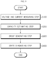
- FIG. 9 is a diagram schematically showing a battery management method according to another embodiment of the present disclosure.
- the battery management method according to another embodiment of the present disclosure may be performed by the battery management apparatus according to an embodiment of the present disclosure.
- the battery management method may include a voltage and current measuring step (S100), a capacity estimating step (S200), a group generating step (S300), and a state diagnosing step (S400).
- S100 voltage and current measuring step
- S200 capacity estimating step
- S300 group generating step
- S400 state diagnosing step
- the voltage and current measuring step (S100) is a step of measuring a voltage and current of a battery cell while the battery cell is being charged or discharged, in a charging and discharging cycle of the battery cell, and may be performed by the measuring unit 110.
- the measuring unit 110 may measure a positive electrode potential and a negative electrode potential of the battery cell 10, and measure the voltage of the battery cell 10 by obtaining a difference between the measured positive electrode potential and the measured negative electrode potential.
- the measuring unit 110 may measure a charging and discharging current of the battery cell 10 by means of a voltmeter A provided on a charging and discharging path of the battery cell 10.
- the capacity estimating step S200 is a step of estimating a capacity of the battery cell based on the current of the battery cell measured in the measuring step S100, and may be performed by the control unit 130.
- the control unit 130 may estimate the capacity of the battery cell 10 using the Ampere counting method.
- the capacity of the battery cell 10 may be a state of charge (SOC) of the battery cell 10.
- the group generating step (S300) is a step of generating a group of charging and discharging cycles having the same charging and discharging C-rate, and may be performed by the control unit 130.
- the storage unit 120 may store a capacity-voltage differential profile and a charging and discharging C-rate in every charging and discharging cycle of the battery cell 10.
- the control unit 130 may generate a group of charging and discharging cycles having the same charging and discharging C-rate among the charging and discharging cycles stored in the storage unit 120.
- the capacity-voltage differential profile and the charging C-rate of the first to sixth charging cycles may be stored in the storage unit 120.
- the control unit 130 may generate a first group including the first charging cycle, the second charging cycle and the third charging cycle having the same charging C-rate, and generate a second group including the fourth charging cycle, the fifth charging cycle and the sixth charging cycle. That is, the charging and discharging cycles included in one group are charged and discharged with the same charging and discharging C-rate.
- the state diagnosing step S400 is a step of diagnosing the state of the battery cell by comparing the capacity-voltage differential profiles corresponding to the charging and discharging cycles included in the same group with each other, and may be performed by the control unit 130.
- the control unit 130 may select charging and discharging cycles included in a group for each group in order to select charging and discharging cycles charged or discharged at the same charging and discharging C-rate.
- the control unit 130 may select a capacity-voltage differential profile corresponding to the selected charging and discharging cycle among the capacity-voltage differential profiles stored in the storage unit 120. In addition, the control unit 130 may diagnose the state of battery cell 10 by comparing the selected capacity-voltage differential profiles with each other.
- control unit 130 may extract a first peak associated with the loss of available lithium of the battery cell 10 from each selected capacity-voltage differential profile.
- the control unit 130 may diagnose whether available lithium of the battery cell 10 is lost according to whether the voltage of the first peak in the selected capacity-voltage differential profile moves toward a high potential as the charging and discharging cycle increases.
- control unit 130 may extract a second peak associated with the positive electrode reaction area of the battery cell 10 from each selected capacity-voltage differential profile.
- the control unit 130 may diagnose whether the positive electrode reaction area of the battery cell 10 is reduced according to whether the capacity change amount per unit voltage of the second peak in the selected capacity-voltage differential profile decreases as the charging and discharging cycle increases.
- control unit 130 may diagnose the state of the battery cell 10 by comparing the capacity-voltage profiles stored in advance in the storage unit 120, as well as diagnose a current state of the battery cell 10 in real time by using a new capacity-voltage profile generated in a state where the battery cell 10 is running.
- control unit 130 may compare the generated new capacity-voltage profile with the capacity-voltage profile stored in advance in the storage unit 120 to diagnose whether available lithium of the battery cell 10 is lost and whether the positive electrode reaction area is reduced.
- the battery management method may diagnose the state of the battery cell 10 even while the battery cell 10 is running.
- the capacity-voltage profiles of the battery cell 10 are accumulated more, the accuracy and reliability of diagnosis on the state of the battery cell 10 may be improved further.
- the embodiments of the present disclosure described above may not be implemented only through an apparatus and a method, but may be implemented through a program that realizes a function corresponding to the configuration of the embodiments of the present disclosure or a recording medium on which the program is recorded.
- the program or recording medium may be easily implemented by those skilled in the art from the above description of the embodiments.
Landscapes
- Physics & Mathematics (AREA)
- General Physics & Mathematics (AREA)
- Engineering & Computer Science (AREA)
- Manufacturing & Machinery (AREA)
- Chemical & Material Sciences (AREA)
- Chemical Kinetics & Catalysis (AREA)
- Electrochemistry (AREA)
- General Chemical & Material Sciences (AREA)
- Microelectronics & Electronic Packaging (AREA)
- Secondary Cells (AREA)
- Tests Of Electric Status Of Batteries (AREA)
- Charge And Discharge Circuits For Batteries Or The Like (AREA)
Applications Claiming Priority (2)
| Application Number | Priority Date | Filing Date | Title |
|---|---|---|---|
| KR1020190112936A KR102714079B1 (ko) | 2019-09-11 | 2019-09-11 | 배터리 관리 장치 및 방법 |
| PCT/KR2020/012195 WO2021049882A1 (fr) | 2019-09-11 | 2020-09-09 | Dispositif et procédé de gestion de batterie |
Publications (3)
| Publication Number | Publication Date |
|---|---|
| EP4012427A1 true EP4012427A1 (fr) | 2022-06-15 |
| EP4012427A4 EP4012427A4 (fr) | 2022-10-12 |
| EP4012427B1 EP4012427B1 (fr) | 2024-07-17 |
Family
ID=74866670
Family Applications (1)
| Application Number | Title | Priority Date | Filing Date |
|---|---|---|---|
| EP20862658.0A Active EP4012427B1 (fr) | 2019-09-11 | 2020-09-09 | Dispositif et procédé de gestion de batterie |
Country Status (9)
| Country | Link |
|---|---|
| US (1) | US11874330B2 (fr) |
| EP (1) | EP4012427B1 (fr) |
| JP (1) | JP7279294B2 (fr) |
| KR (1) | KR102714079B1 (fr) |
| CN (1) | CN114270202B (fr) |
| ES (1) | ES2994208T3 (fr) |
| HU (1) | HUE068013T2 (fr) |
| PL (1) | PL4012427T3 (fr) |
| WO (1) | WO2021049882A1 (fr) |
Cited By (1)
| Publication number | Priority date | Publication date | Assignee | Title |
|---|---|---|---|---|
| EP4206706A4 (fr) * | 2021-02-19 | 2024-05-01 | LG Energy Solution, Ltd. | Dispositif et procédé de diagnostic d'état d'une batterie |
Families Citing this family (27)
| Publication number | Priority date | Publication date | Assignee | Title |
|---|---|---|---|---|
| KR102847768B1 (ko) | 2020-11-17 | 2025-08-18 | 주식회사 엘지에너지솔루션 | 배터리 관리 장치 및 방법 |
| KR20220117063A (ko) * | 2021-02-16 | 2022-08-23 | 주식회사 엘지에너지솔루션 | 배터리 충방전 장치 및 방법 |
| CN113296010B (zh) * | 2021-04-27 | 2022-10-04 | 国网上海市电力公司 | 一种基于差分电压分析的电池健康状态在线评估方法 |
| CN114117825B (zh) * | 2021-07-02 | 2025-07-25 | 上海美克生能源科技有限公司 | 一种电池的运维方法、装置及电子设备 |
| KR102674286B1 (ko) * | 2021-08-02 | 2024-06-10 | 주식회사 엘지에너지솔루션 | 배터리 관리 장치 및 방법 |
| KR102889264B1 (ko) | 2021-09-09 | 2025-11-20 | 주식회사 엘지에너지솔루션 | 배터리 셀의 용량 산출 장치 및 방법 |
| KR102937194B1 (ko) * | 2021-12-06 | 2026-03-09 | 주식회사 엘지에너지솔루션 | 배터리 상태 추정 장치 및 방법 |
| CN114895197B (zh) * | 2022-04-26 | 2025-05-02 | 江苏海基新能源股份有限公司 | 一种磷酸铁锂电池循环性能的评价方法 |
| KR102672284B1 (ko) | 2022-06-21 | 2024-06-03 | 주식회사 엘지에너지솔루션 | 배터리 관리 장치 및 방법 |
| WO2024049177A1 (fr) * | 2022-09-02 | 2024-03-07 | 주식회사 엘지에너지솔루션 | Dispositif de diagnostic de batterie, bloc-batterie, véhicule électrique et procédé de diagnostic de batterie |
| KR20240037583A (ko) * | 2022-09-15 | 2024-03-22 | 주식회사 엘지에너지솔루션 | 배터리 셀 퇴화도 진단 방법 및 이를 이용하는 배터리 시스템 |
| KR102937946B1 (ko) * | 2022-12-23 | 2026-03-10 | 주식회사 엘지에너지솔루션 | 배터리 진단 장치 및 방법 |
| KR102905305B1 (ko) * | 2023-01-25 | 2025-12-26 | 주식회사 엘지에너지솔루션 | 배터리 진단 장치 및 방법 |
| CN119137491A (zh) * | 2023-01-25 | 2024-12-13 | 株式会社Lg新能源 | 用于诊断电池的装置和方法 |
| KR102905332B1 (ko) * | 2023-01-25 | 2025-12-26 | 주식회사 엘지에너지솔루션 | 배터리 진단 장치 및 방법 |
| KR102831587B1 (ko) * | 2023-02-03 | 2025-07-09 | 주식회사 엘지에너지솔루션 | 배터리 진단 장치 및 이의 동작 방법 |
| EP4733785A1 (fr) * | 2023-08-04 | 2026-04-29 | LG Energy Solution, Ltd. | Appareil de diagnostic d'une propriété de résistance d'une cellule unitaire, procédé de diagnostic associé, et cellule unitaire pour batterie secondaire satisfaisant à une condition spécifique selon le procédé |
| EP4521509B1 (fr) * | 2023-09-07 | 2026-02-04 | Automotive Cells Company SE | Procédé de surveillance d'un bloc-batterie au lithium-ion, module ou cellule, et bloc-batterie associé |
| KR102927734B1 (ko) * | 2024-01-15 | 2026-02-12 | 주식회사 엘지에너지솔루션 | 배터리 진단 장치 및 방법 |
| KR102888925B1 (ko) * | 2024-01-17 | 2025-11-19 | 주식회사 엘지에너지솔루션 | 배터리 진단 장치 및 방법 |
| KR102825303B1 (ko) * | 2024-01-26 | 2025-06-24 | 주식회사 엘지에너지솔루션 | 배터리 정보 제공 장치 및 방법 |
| KR102813990B1 (ko) * | 2024-01-31 | 2025-05-27 | 주식회사 엘지에너지솔루션 | 배터리 진단 장치 및 방법 |
| WO2025170262A1 (fr) * | 2024-02-06 | 2025-08-14 | 주식회사 엘지에너지솔루션 | Appareil de diagnostic de batterie et procédé de diagnostic de batterie |
| KR20250128724A (ko) * | 2024-02-21 | 2025-08-28 | 주식회사 엘지에너지솔루션 | 배터리 용량 추정 장치 및 방법 |
| KR20250152398A (ko) * | 2024-04-16 | 2025-10-23 | 삼성에스디아이 주식회사 | 전지 특성 검출 장치 및 그 방법 |
| KR20250167948A (ko) * | 2024-05-23 | 2025-12-02 | 삼성에스디아이 주식회사 | 배터리의 음극 안전도 추정 방법 및 이를 이용한 배터리 시스템 |
| KR20250177279A (ko) * | 2024-06-14 | 2025-12-23 | 주식회사 엘지에너지솔루션 | 전지셀 양불판정 시스템 및 방법 |
Family Cites Families (28)
| Publication number | Priority date | Publication date | Assignee | Title |
|---|---|---|---|---|
| JP4561859B2 (ja) * | 2008-04-01 | 2010-10-13 | トヨタ自動車株式会社 | 二次電池システム |
| JP5625244B2 (ja) | 2009-02-27 | 2014-11-19 | 日産自動車株式会社 | 二次電池の容量推定装置 |
| US8653793B2 (en) * | 2009-09-25 | 2014-02-18 | Toyota Jidosha Kabushiki Kaisha | Secondary battery system |
| US9046586B2 (en) * | 2010-03-29 | 2015-06-02 | Panasonic Intellectual Property Management Co., Ltd. | Method and device for diagnosing secondary battery degradation |
| TWM396594U (en) | 2010-04-09 | 2011-01-21 | Ecolighting Inc | Structural improvement for externally-connected type electrical control lamp |
| JP5682955B2 (ja) * | 2010-08-04 | 2015-03-11 | Necエナジーデバイス株式会社 | リチウム二次電池の制御システム、およびリチウム二次電池の状態検出方法 |
| US8680815B2 (en) * | 2010-11-01 | 2014-03-25 | GM Global Technology Operations LLC | Method and apparatus for assessing battery state of health |
| JP5940145B2 (ja) | 2012-04-20 | 2016-06-29 | 日立オートモティブシステムズ株式会社 | 二次電池システム、二次電池の劣化状態判断方法 |
| JP2013247003A (ja) * | 2012-05-28 | 2013-12-09 | Sony Corp | 二次電池の充電制御装置、二次電池の充電制御方法、二次電池の充電状態推定装置、二次電池の充電状態推定方法、二次電池の劣化度推定装置、二次電池の劣化度推定方法、及び、二次電池装置 |
| JP5662968B2 (ja) | 2012-06-19 | 2015-02-04 | 株式会社日立製作所 | 二次電池の検査システム、充放電機、及び検査方法 |
| JP2015060761A (ja) * | 2013-09-19 | 2015-03-30 | 株式会社東芝 | 二次電池の劣化診断システム及び劣化診断方法 |
| EP3051305B1 (fr) * | 2013-09-25 | 2019-04-17 | Hitachi, Ltd. | Méthode de détermination d'état pour batterie rechargeable, appareil de détermination d'état pour batterie rechargeable, système de batterie rechargeable, et appareil de commande de charge/décharge doté de l'appareil de détermination d'état |
| JP6314043B2 (ja) | 2014-06-26 | 2018-04-18 | プライムアースEvエナジー株式会社 | 蓄電池の検査方法及び蓄電池の検査装置 |
| JP6123844B2 (ja) | 2014-09-01 | 2017-05-10 | 横河電機株式会社 | 二次電池容量測定システム及び二次電池容量測定方法 |
| EP2990818B1 (fr) * | 2014-09-01 | 2019-11-27 | Yokogawa Electric Corporation | Système et procédé de mesure de capacité de batterie secondaire |
| DE112016003166B4 (de) * | 2015-07-13 | 2019-05-23 | Mitsubishi Electric Corporation | Verfahren zum schätzen des ladezustandes für eine lithium-ionen-batterie und ladezustands-schätzvorrichtung für eine lithium-ionen-batterie |
| KR101897859B1 (ko) | 2015-08-24 | 2018-09-12 | 주식회사 엘지화학 | 리튬 석출 탐지 방법, 이를 이용한 이차전지 충전 방법과 장치 및 이차전지 시스템 |
| JP6437407B2 (ja) * | 2015-09-16 | 2018-12-12 | 株式会社東芝 | 電池パックおよび充電制御方法 |
| JP6500789B2 (ja) * | 2016-01-19 | 2019-04-17 | トヨタ自動車株式会社 | 二次電池の制御システム |
| JP2017133870A (ja) * | 2016-01-26 | 2017-08-03 | トヨタ自動車株式会社 | リチウムイオン二次電池の異常劣化検知装置および異常劣化検知方法 |
| JP6323501B2 (ja) | 2016-06-21 | 2018-05-16 | マツダ株式会社 | リチウムイオン電池の診断装置 |
| JP2020504994A (ja) * | 2016-12-29 | 2020-02-13 | ヴィート エヌブイ | ハイブリッドバッテリ充電器/試験器 |
| JP2018205139A (ja) | 2017-06-05 | 2018-12-27 | 三菱自動車工業株式会社 | 二次電池システム |
| US11226374B2 (en) | 2017-10-17 | 2022-01-18 | The Board Of Trustees Of The Leland Stanford Junior University | Data-driven model for lithium-ion battery capacity fade and lifetime prediction |
| KR20190112936A (ko) | 2018-03-27 | 2019-10-08 | 주식회사 영원코퍼레이션 | 음식물 쓰레기 처리기용 거름망 소제장치 |
| CN108896913A (zh) | 2018-05-10 | 2018-11-27 | 燕山大学 | 一种锂离子电池健康状态的估算方法 |
| CN109031153B (zh) | 2018-10-16 | 2020-01-24 | 北京交通大学 | 一种锂离子电池的健康状态在线估计方法 |
| CN110045293A (zh) * | 2019-03-15 | 2019-07-23 | 天津力神电池股份有限公司 | 一种无损分析电池活性物质材料失效的方法 |
-
2019
- 2019-09-11 KR KR1020190112936A patent/KR102714079B1/ko active Active
-
2020
- 2020-09-09 US US17/626,188 patent/US11874330B2/en active Active
- 2020-09-09 WO PCT/KR2020/012195 patent/WO2021049882A1/fr not_active Ceased
- 2020-09-09 PL PL20862658.0T patent/PL4012427T3/pl unknown
- 2020-09-09 EP EP20862658.0A patent/EP4012427B1/fr active Active
- 2020-09-09 ES ES20862658T patent/ES2994208T3/es active Active
- 2020-09-09 CN CN202080048458.8A patent/CN114270202B/zh active Active
- 2020-09-09 JP JP2021577147A patent/JP7279294B2/ja active Active
- 2020-09-09 HU HUE20862658A patent/HUE068013T2/hu unknown
Cited By (2)
| Publication number | Priority date | Publication date | Assignee | Title |
|---|---|---|---|---|
| EP4206706A4 (fr) * | 2021-02-19 | 2024-05-01 | LG Energy Solution, Ltd. | Dispositif et procédé de diagnostic d'état d'une batterie |
| US12379418B2 (en) | 2021-02-19 | 2025-08-05 | Lg Energy Solution, Ltd. | Apparatus and method for diagnosing state of battery |
Also Published As
| Publication number | Publication date |
|---|---|
| JP2022539744A (ja) | 2022-09-13 |
| WO2021049882A1 (fr) | 2021-03-18 |
| KR20210031226A (ko) | 2021-03-19 |
| KR102714079B1 (ko) | 2024-10-04 |
| US20220276314A1 (en) | 2022-09-01 |
| EP4012427B1 (fr) | 2024-07-17 |
| EP4012427A4 (fr) | 2022-10-12 |
| HUE068013T2 (hu) | 2024-12-28 |
| ES2994208T3 (en) | 2025-01-20 |
| CN114270202A (zh) | 2022-04-01 |
| JP7279294B2 (ja) | 2023-05-23 |
| US11874330B2 (en) | 2024-01-16 |
| CN114270202B (zh) | 2024-04-09 |
| PL4012427T3 (pl) | 2024-09-23 |
Similar Documents
| Publication | Publication Date | Title |
|---|---|---|
| EP4012427B1 (fr) | Dispositif et procédé de gestion de batterie | |
| CN115210594B (zh) | 用于诊断电池的状态的设备及方法、电池组和车辆 | |
| EP4206706B1 (fr) | Appareil et procédé de diagnostic d'état d'une batterie | |
| US20250389775A1 (en) | Battery Management Apparatus and Method | |
| US12210065B2 (en) | Battery diagnosing apparatus and method | |
| US20240044995A1 (en) | Battery Management Apparatus and Method | |
| EP4199182B1 (fr) | Dispositif et procédé de diagnostic de batterie | |
| EP4145158B1 (fr) | Dispositif et procédé de diagnostic de batterie | |
| EP4141462A1 (fr) | Dispositif de diagnostic de batterie et procédé de diagnostic de batterie | |
| EP4376161A1 (fr) | Appareil et procédé de gestion de batterie | |
| US12352818B2 (en) | Battery management apparatus and method | |
| EP4152020B1 (fr) | Appareil et procédé de gestion de batterie | |
| US20250316780A1 (en) | Battery Management Apparatus and Method | |
| EP4152025A1 (fr) | Dispositif et procédé de diagnostic de batterie | |
| EP4729963A1 (fr) | Appareil et procédé de diagnostic de batterie | |
| EP4468002A1 (fr) | Appareil et procédé de diagnostic de batterie | |
| EP4579261A1 (fr) | Appareil et procédé de diagnostic de batterie | |
| US12282068B2 (en) | Lithium precipitation detecting apparatus and method | |
| EP4675294A1 (fr) | Appareil et procédé de diagnostic de batterie | |
| US20250244404A1 (en) | Apparatus and method for diagnosing battery | |
| EP4715404A1 (fr) | Appareil et procédé de gestion de batterie | |
| US20260066365A1 (en) | Battery management apparatus and method |
Legal Events
| Date | Code | Title | Description |
|---|---|---|---|
| STAA | Information on the status of an ep patent application or granted ep patent |
Free format text: STATUS: THE INTERNATIONAL PUBLICATION HAS BEEN MADE |
|
| PUAI | Public reference made under article 153(3) epc to a published international application that has entered the european phase |
Free format text: ORIGINAL CODE: 0009012 |
|
| STAA | Information on the status of an ep patent application or granted ep patent |
Free format text: STATUS: REQUEST FOR EXAMINATION WAS MADE |
|
| 17P | Request for examination filed |
Effective date: 20220308 |
|
| AK | Designated contracting states |
Kind code of ref document: A1 Designated state(s): AL AT BE BG CH CY CZ DE DK EE ES FI FR GB GR HR HU IE IS IT LI LT LU LV MC MK MT NL NO PL PT RO RS SE SI SK SM TR |
|
| A4 | Supplementary search report drawn up and despatched |
Effective date: 20220909 |
|
| RIC1 | Information provided on ipc code assigned before grant |
Ipc: H02J 7/00 20060101ALI20220905BHEP Ipc: H01M 10/052 20100101ALI20220905BHEP Ipc: H01M 10/44 20060101ALI20220905BHEP Ipc: H01M 10/42 20060101ALI20220905BHEP Ipc: H01M 10/48 20060101ALI20220905BHEP Ipc: G01R 31/396 20190101ALI20220905BHEP Ipc: G01R 31/392 20190101ALI20220905BHEP Ipc: G01R 31/382 20190101ALI20220905BHEP Ipc: G01R 31/36 20200101AFI20220905BHEP |
|
| DAV | Request for validation of the european patent (deleted) | ||
| DAX | Request for extension of the european patent (deleted) | ||
| GRAP | Despatch of communication of intention to grant a patent |
Free format text: ORIGINAL CODE: EPIDOSNIGR1 |
|
| STAA | Information on the status of an ep patent application or granted ep patent |
Free format text: STATUS: GRANT OF PATENT IS INTENDED |
|
| RIC1 | Information provided on ipc code assigned before grant |
Ipc: H02J 7/00 20060101ALI20240312BHEP Ipc: H01M 10/052 20100101ALI20240312BHEP Ipc: H01M 10/44 20060101ALI20240312BHEP Ipc: H01M 10/42 20060101ALI20240312BHEP Ipc: H01M 10/48 20060101ALI20240312BHEP Ipc: G01R 31/396 20190101ALI20240312BHEP Ipc: G01R 31/392 20190101ALI20240312BHEP Ipc: G01R 31/382 20190101ALI20240312BHEP Ipc: G01R 31/36 20200101AFI20240312BHEP |
|
| INTG | Intention to grant announced |
Effective date: 20240325 |
|
| P01 | Opt-out of the competence of the unified patent court (upc) registered |
Effective date: 20240404 |
|
| GRAS | Grant fee paid |
Free format text: ORIGINAL CODE: EPIDOSNIGR3 |
|
| GRAA | (expected) grant |
Free format text: ORIGINAL CODE: 0009210 |
|
| STAA | Information on the status of an ep patent application or granted ep patent |
Free format text: STATUS: THE PATENT HAS BEEN GRANTED |
|
| AK | Designated contracting states |
Kind code of ref document: B1 Designated state(s): AL AT BE BG CH CY CZ DE DK EE ES FI FR GB GR HR HU IE IS IT LI LT LU LV MC MK MT NL NO PL PT RO RS SE SI SK SM TR |
|
| REG | Reference to a national code |
Ref country code: CH Ref legal event code: EP |
|
| REG | Reference to a national code |
Ref country code: DE Ref legal event code: R096 Ref document number: 602020034275 Country of ref document: DE |
|
| REG | Reference to a national code |
Ref country code: IE Ref legal event code: FG4D |
|
| REG | Reference to a national code |
Ref country code: SE Ref legal event code: TRGR |
|
| REG | Reference to a national code |
Ref country code: LT Ref legal event code: MG9D |
|
| REG | Reference to a national code |
Ref country code: NL Ref legal event code: MP Effective date: 20240717 |
|
| PG25 | Lapsed in a contracting state [announced via postgrant information from national office to epo] |
Ref country code: PT Free format text: LAPSE BECAUSE OF FAILURE TO SUBMIT A TRANSLATION OF THE DESCRIPTION OR TO PAY THE FEE WITHIN THE PRESCRIBED TIME-LIMIT Effective date: 20241118 |
|
| REG | Reference to a national code |
Ref country code: AT Ref legal event code: MK05 Ref document number: 1704629 Country of ref document: AT Kind code of ref document: T Effective date: 20240717 |
|
| PG25 | Lapsed in a contracting state [announced via postgrant information from national office to epo] |
Ref country code: NL Free format text: LAPSE BECAUSE OF FAILURE TO SUBMIT A TRANSLATION OF THE DESCRIPTION OR TO PAY THE FEE WITHIN THE PRESCRIBED TIME-LIMIT Effective date: 20240717 |
|
| REG | Reference to a national code |
Ref country code: HU Ref legal event code: AG4A Ref document number: E068013 Country of ref document: HU |
|
| PG25 | Lapsed in a contracting state [announced via postgrant information from national office to epo] |
Ref country code: PT Free format text: LAPSE BECAUSE OF FAILURE TO SUBMIT A TRANSLATION OF THE DESCRIPTION OR TO PAY THE FEE WITHIN THE PRESCRIBED TIME-LIMIT Effective date: 20241118 Ref country code: NL Free format text: LAPSE BECAUSE OF FAILURE TO SUBMIT A TRANSLATION OF THE DESCRIPTION OR TO PAY THE FEE WITHIN THE PRESCRIBED TIME-LIMIT Effective date: 20240717 |
|
| PG25 | Lapsed in a contracting state [announced via postgrant information from national office to epo] |
Ref country code: NO Free format text: LAPSE BECAUSE OF FAILURE TO SUBMIT A TRANSLATION OF THE DESCRIPTION OR TO PAY THE FEE WITHIN THE PRESCRIBED TIME-LIMIT Effective date: 20241017 |
|
| PG25 | Lapsed in a contracting state [announced via postgrant information from national office to epo] |
Ref country code: GR Free format text: LAPSE BECAUSE OF FAILURE TO SUBMIT A TRANSLATION OF THE DESCRIPTION OR TO PAY THE FEE WITHIN THE PRESCRIBED TIME-LIMIT Effective date: 20241018 Ref country code: FI Free format text: LAPSE BECAUSE OF FAILURE TO SUBMIT A TRANSLATION OF THE DESCRIPTION OR TO PAY THE FEE WITHIN THE PRESCRIBED TIME-LIMIT Effective date: 20240717 |
|
| PG25 | Lapsed in a contracting state [announced via postgrant information from national office to epo] |
Ref country code: BG Free format text: LAPSE BECAUSE OF FAILURE TO SUBMIT A TRANSLATION OF THE DESCRIPTION OR TO PAY THE FEE WITHIN THE PRESCRIBED TIME-LIMIT Effective date: 20240717 |
|
| REG | Reference to a national code |
Ref country code: ES Ref legal event code: FG2A Ref document number: 2994208 Country of ref document: ES Kind code of ref document: T3 Effective date: 20250120 |
|
| PG25 | Lapsed in a contracting state [announced via postgrant information from national office to epo] |
Ref country code: LV Free format text: LAPSE BECAUSE OF FAILURE TO SUBMIT A TRANSLATION OF THE DESCRIPTION OR TO PAY THE FEE WITHIN THE PRESCRIBED TIME-LIMIT Effective date: 20240717 |
|
| PG25 | Lapsed in a contracting state [announced via postgrant information from national office to epo] |
Ref country code: IS Free format text: LAPSE BECAUSE OF FAILURE TO SUBMIT A TRANSLATION OF THE DESCRIPTION OR TO PAY THE FEE WITHIN THE PRESCRIBED TIME-LIMIT Effective date: 20241117 Ref country code: AT Free format text: LAPSE BECAUSE OF FAILURE TO SUBMIT A TRANSLATION OF THE DESCRIPTION OR TO PAY THE FEE WITHIN THE PRESCRIBED TIME-LIMIT Effective date: 20240717 |
|
| PG25 | Lapsed in a contracting state [announced via postgrant information from national office to epo] |
Ref country code: HR Free format text: LAPSE BECAUSE OF FAILURE TO SUBMIT A TRANSLATION OF THE DESCRIPTION OR TO PAY THE FEE WITHIN THE PRESCRIBED TIME-LIMIT Effective date: 20240717 |
|
| PG25 | Lapsed in a contracting state [announced via postgrant information from national office to epo] |
Ref country code: RS Free format text: LAPSE BECAUSE OF FAILURE TO SUBMIT A TRANSLATION OF THE DESCRIPTION OR TO PAY THE FEE WITHIN THE PRESCRIBED TIME-LIMIT Effective date: 20241017 |
|
| PG25 | Lapsed in a contracting state [announced via postgrant information from national office to epo] |
Ref country code: RS Free format text: LAPSE BECAUSE OF FAILURE TO SUBMIT A TRANSLATION OF THE DESCRIPTION OR TO PAY THE FEE WITHIN THE PRESCRIBED TIME-LIMIT Effective date: 20241017 Ref country code: NO Free format text: LAPSE BECAUSE OF FAILURE TO SUBMIT A TRANSLATION OF THE DESCRIPTION OR TO PAY THE FEE WITHIN THE PRESCRIBED TIME-LIMIT Effective date: 20241017 Ref country code: LV Free format text: LAPSE BECAUSE OF FAILURE TO SUBMIT A TRANSLATION OF THE DESCRIPTION OR TO PAY THE FEE WITHIN THE PRESCRIBED TIME-LIMIT Effective date: 20240717 Ref country code: IS Free format text: LAPSE BECAUSE OF FAILURE TO SUBMIT A TRANSLATION OF THE DESCRIPTION OR TO PAY THE FEE WITHIN THE PRESCRIBED TIME-LIMIT Effective date: 20241117 Ref country code: HR Free format text: LAPSE BECAUSE OF FAILURE TO SUBMIT A TRANSLATION OF THE DESCRIPTION OR TO PAY THE FEE WITHIN THE PRESCRIBED TIME-LIMIT Effective date: 20240717 Ref country code: GR Free format text: LAPSE BECAUSE OF FAILURE TO SUBMIT A TRANSLATION OF THE DESCRIPTION OR TO PAY THE FEE WITHIN THE PRESCRIBED TIME-LIMIT Effective date: 20241018 Ref country code: FI Free format text: LAPSE BECAUSE OF FAILURE TO SUBMIT A TRANSLATION OF THE DESCRIPTION OR TO PAY THE FEE WITHIN THE PRESCRIBED TIME-LIMIT Effective date: 20240717 Ref country code: BG Free format text: LAPSE BECAUSE OF FAILURE TO SUBMIT A TRANSLATION OF THE DESCRIPTION OR TO PAY THE FEE WITHIN THE PRESCRIBED TIME-LIMIT Effective date: 20240717 Ref country code: AT Free format text: LAPSE BECAUSE OF FAILURE TO SUBMIT A TRANSLATION OF THE DESCRIPTION OR TO PAY THE FEE WITHIN THE PRESCRIBED TIME-LIMIT Effective date: 20240717 |
|
| PG25 | Lapsed in a contracting state [announced via postgrant information from national office to epo] |
Ref country code: RO Free format text: LAPSE BECAUSE OF FAILURE TO SUBMIT A TRANSLATION OF THE DESCRIPTION OR TO PAY THE FEE WITHIN THE PRESCRIBED TIME-LIMIT Effective date: 20240717 Ref country code: DK Free format text: LAPSE BECAUSE OF FAILURE TO SUBMIT A TRANSLATION OF THE DESCRIPTION OR TO PAY THE FEE WITHIN THE PRESCRIBED TIME-LIMIT Effective date: 20240717 Ref country code: SM Free format text: LAPSE BECAUSE OF FAILURE TO SUBMIT A TRANSLATION OF THE DESCRIPTION OR TO PAY THE FEE WITHIN THE PRESCRIBED TIME-LIMIT Effective date: 20240717 |
|
| REG | Reference to a national code |
Ref country code: DE Ref legal event code: R097 Ref document number: 602020034275 Country of ref document: DE |
|
| PG25 | Lapsed in a contracting state [announced via postgrant information from national office to epo] |
Ref country code: MC Free format text: LAPSE BECAUSE OF FAILURE TO SUBMIT A TRANSLATION OF THE DESCRIPTION OR TO PAY THE FEE WITHIN THE PRESCRIBED TIME-LIMIT Effective date: 20240717 Ref country code: EE Free format text: LAPSE BECAUSE OF FAILURE TO SUBMIT A TRANSLATION OF THE DESCRIPTION OR TO PAY THE FEE WITHIN THE PRESCRIBED TIME-LIMIT Effective date: 20240717 |
|
| PG25 | Lapsed in a contracting state [announced via postgrant information from national office to epo] |
Ref country code: CZ Free format text: LAPSE BECAUSE OF FAILURE TO SUBMIT A TRANSLATION OF THE DESCRIPTION OR TO PAY THE FEE WITHIN THE PRESCRIBED TIME-LIMIT Effective date: 20240717 |
|
| PG25 | Lapsed in a contracting state [announced via postgrant information from national office to epo] |
Ref country code: SK Free format text: LAPSE BECAUSE OF FAILURE TO SUBMIT A TRANSLATION OF THE DESCRIPTION OR TO PAY THE FEE WITHIN THE PRESCRIBED TIME-LIMIT Effective date: 20240717 |
|
| REG | Reference to a national code |
Ref country code: CH Ref legal event code: PL |
|
| PG25 | Lapsed in a contracting state [announced via postgrant information from national office to epo] |
Ref country code: LU Free format text: LAPSE BECAUSE OF NON-PAYMENT OF DUE FEES Effective date: 20240909 |
|
| PLBE | No opposition filed within time limit |
Free format text: ORIGINAL CODE: 0009261 |
|
| STAA | Information on the status of an ep patent application or granted ep patent |
Free format text: STATUS: NO OPPOSITION FILED WITHIN TIME LIMIT |
|
| 26N | No opposition filed |
Effective date: 20250422 |
|
| PGFP | Annual fee paid to national office [announced via postgrant information from national office to epo] |
Ref country code: BE Payment date: 20250425 Year of fee payment: 6 |
|
| PG25 | Lapsed in a contracting state [announced via postgrant information from national office to epo] |
Ref country code: CH Free format text: LAPSE BECAUSE OF NON-PAYMENT OF DUE FEES Effective date: 20240930 |
|
| PG25 | Lapsed in a contracting state [announced via postgrant information from national office to epo] |
Ref country code: IE Free format text: LAPSE BECAUSE OF NON-PAYMENT OF DUE FEES Effective date: 20240909 |
|
| PGFP | Annual fee paid to national office [announced via postgrant information from national office to epo] |
Ref country code: DE Payment date: 20250820 Year of fee payment: 6 |
|
| PGFP | Annual fee paid to national office [announced via postgrant information from national office to epo] |
Ref country code: PL Payment date: 20250822 Year of fee payment: 6 |
|
| PGFP | Annual fee paid to national office [announced via postgrant information from national office to epo] |
Ref country code: HU Payment date: 20250929 Year of fee payment: 6 Ref country code: GB Payment date: 20250820 Year of fee payment: 6 |
|
| PGFP | Annual fee paid to national office [announced via postgrant information from national office to epo] |
Ref country code: FR Payment date: 20250821 Year of fee payment: 6 |
|
| PGFP | Annual fee paid to national office [announced via postgrant information from national office to epo] |
Ref country code: SE Payment date: 20250821 Year of fee payment: 6 |
|
| PG25 | Lapsed in a contracting state [announced via postgrant information from national office to epo] |
Ref country code: IT Free format text: LAPSE BECAUSE OF FAILURE TO SUBMIT A TRANSLATION OF THE DESCRIPTION OR TO PAY THE FEE WITHIN THE PRESCRIBED TIME-LIMIT Effective date: 20240717 Ref country code: CY Free format text: LAPSE BECAUSE OF FAILURE TO SUBMIT A TRANSLATION OF THE DESCRIPTION OR TO PAY THE FEE WITHIN THE PRESCRIBED TIME-LIMIT; INVALID AB INITIO Effective date: 20200909 |
|
| PGFP | Annual fee paid to national office [announced via postgrant information from national office to epo] |
Ref country code: ES Payment date: 20251007 Year of fee payment: 6 |