EP4012480A1 - Am kopf montiertes gerät mit einem projektor zum projizieren eines bildes - Google Patents
Am kopf montiertes gerät mit einem projektor zum projizieren eines bildes Download PDFInfo
- Publication number
- EP4012480A1 EP4012480A1 EP21213295.5A EP21213295A EP4012480A1 EP 4012480 A1 EP4012480 A1 EP 4012480A1 EP 21213295 A EP21213295 A EP 21213295A EP 4012480 A1 EP4012480 A1 EP 4012480A1
- Authority
- EP
- European Patent Office
- Prior art keywords
- projector
- mounted device
- light sources
- head mounted
- image
- Prior art date
- Legal status (The legal status is an assumption and is not a legal conclusion. Google has not performed a legal analysis and makes no representation as to the accuracy of the status listed.)
- Pending
Links
Images


Classifications
-
- G—PHYSICS
- G02—OPTICS
- G02B—OPTICAL ELEMENTS, SYSTEMS OR APPARATUS
- G02B26/00—Optical devices or arrangements for the control of light using movable or deformable optical elements
- G02B26/08—Optical devices or arrangements for the control of light using movable or deformable optical elements for controlling the direction of light
- G02B26/10—Scanning systems
- G02B26/105—Scanning systems with one or more pivoting mirrors or galvano-mirrors
-
- B—PERFORMING OPERATIONS; TRANSPORTING
- B81—MICROSTRUCTURAL TECHNOLOGY
- B81B—MICROSTRUCTURAL DEVICES OR SYSTEMS, e.g. MICROMECHANICAL DEVICES
- B81B7/00—Microstructural systems ; Auxiliary parts of microstructural devices or systems
- B81B7/02—Microstructural systems ; Auxiliary parts of microstructural devices or systems containing distinct electrical or optical devices of particular relevance for their function, e.g. microelectro-mechanical systems [MEMS]
-
- G—PHYSICS
- G02—OPTICS
- G02B—OPTICAL ELEMENTS, SYSTEMS OR APPARATUS
- G02B26/00—Optical devices or arrangements for the control of light using movable or deformable optical elements
- G02B26/08—Optical devices or arrangements for the control of light using movable or deformable optical elements for controlling the direction of light
- G02B26/0816—Optical devices or arrangements for the control of light using movable or deformable optical elements for controlling the direction of light by means of one or more reflecting elements
- G02B26/0833—Optical devices or arrangements for the control of light using movable or deformable optical elements for controlling the direction of light by means of one or more reflecting elements the reflecting element being a micromechanical device, e.g. a MEMS mirror, DMD
-
- G—PHYSICS
- G02—OPTICS
- G02B—OPTICAL ELEMENTS, SYSTEMS OR APPARATUS
- G02B27/00—Optical systems or apparatus not provided for by any of the groups G02B1/00 - G02B26/00, G02B30/00
- G02B27/01—Head-up displays
- G02B27/017—Head mounted
- G02B27/0172—Head mounted characterised by optical features
-
- G—PHYSICS
- G03—PHOTOGRAPHY; CINEMATOGRAPHY; ANALOGOUS TECHNIQUES USING WAVES OTHER THAN OPTICAL WAVES; ELECTROGRAPHY; HOLOGRAPHY
- G03B—APPARATUS OR ARRANGEMENTS FOR TAKING PHOTOGRAPHS OR FOR PROJECTING OR VIEWING THEM; APPARATUS OR ARRANGEMENTS EMPLOYING ANALOGOUS TECHNIQUES USING WAVES OTHER THAN OPTICAL WAVES; ACCESSORIES THEREFOR
- G03B21/00—Projectors or projection-type viewers; Accessories therefor
- G03B21/14—Details
- G03B21/20—Lamp housings
- G03B21/2006—Lamp housings characterised by the light source
- G03B21/2033—LED or laser light sources
- G03B21/204—LED or laser light sources using secondary light emission, e.g. luminescence or fluorescence
-
- H—ELECTRICITY
- H04—ELECTRIC COMMUNICATION TECHNIQUE
- H04N—PICTORIAL COMMUNICATION, e.g. TELEVISION
- H04N3/00—Scanning details of television systems; Combination thereof with generation of supply voltages
- H04N3/02—Scanning details of television systems; Combination thereof with generation of supply voltages by optical-mechanical means only
- H04N3/08—Scanning details of television systems; Combination thereof with generation of supply voltages by optical-mechanical means only having a moving reflector
-
- H—ELECTRICITY
- H04—ELECTRIC COMMUNICATION TECHNIQUE
- H04N—PICTORIAL COMMUNICATION, e.g. TELEVISION
- H04N9/00—Details of colour television systems
- H04N9/12—Picture reproducers
- H04N9/31—Projection devices for colour picture display, e.g. using electronic spatial light modulators [ESLM]
- H04N9/3129—Projection devices for colour picture display, e.g. using electronic spatial light modulators [ESLM] scanning a light beam on the display screen
-
- H—ELECTRICITY
- H04—ELECTRIC COMMUNICATION TECHNIQUE
- H04N—PICTORIAL COMMUNICATION, e.g. TELEVISION
- H04N9/00—Details of colour television systems
- H04N9/12—Picture reproducers
- H04N9/31—Projection devices for colour picture display, e.g. using electronic spatial light modulators [ESLM]
- H04N9/3138—Projection devices for colour picture display, e.g. using electronic spatial light modulators [ESLM] using arrays of modulated light sources
-
- H—ELECTRICITY
- H04—ELECTRIC COMMUNICATION TECHNIQUE
- H04N—PICTORIAL COMMUNICATION, e.g. TELEVISION
- H04N9/00—Details of colour television systems
- H04N9/12—Picture reproducers
- H04N9/31—Projection devices for colour picture display, e.g. using electronic spatial light modulators [ESLM]
- H04N9/3141—Constructional details thereof
- H04N9/3144—Cooling systems
-
- H—ELECTRICITY
- H04—ELECTRIC COMMUNICATION TECHNIQUE
- H04N—PICTORIAL COMMUNICATION, e.g. TELEVISION
- H04N9/00—Details of colour television systems
- H04N9/12—Picture reproducers
- H04N9/31—Projection devices for colour picture display, e.g. using electronic spatial light modulators [ESLM]
- H04N9/3141—Constructional details thereof
- H04N9/3173—Constructional details thereof wherein the projection device is specially adapted for enhanced portability
-
- B—PERFORMING OPERATIONS; TRANSPORTING
- B81—MICROSTRUCTURAL TECHNOLOGY
- B81B—MICROSTRUCTURAL DEVICES OR SYSTEMS, e.g. MICROMECHANICAL DEVICES
- B81B2201/00—Specific applications of microelectromechanical systems
- B81B2201/04—Optical MEMS
- B81B2201/042—Micromirrors, not used as optical switches
-
- G—PHYSICS
- G02—OPTICS
- G02B—OPTICAL ELEMENTS, SYSTEMS OR APPARATUS
- G02B27/00—Optical systems or apparatus not provided for by any of the groups G02B1/00 - G02B26/00, G02B30/00
- G02B27/01—Head-up displays
- G02B27/017—Head mounted
- G02B2027/0178—Eyeglass type
Definitions
- the inventions relates to a projector configured to be embedded into a portable device and to project an image towards a surface reflecting light towards an eye of a user.
- the invention further relates to a portable device comprising such projector.
- a micro-display intended to be embedded into a portable device such as a mobile phone or a head mounted device, comprises a matrix of light sources with micron size pixels.
- micro-displays comprising a laser source or a light-emitting diode (LED), or three laser sources or LEDs in order to make a colored image, and a microelectromechanical system (MEMS).
- the MEMS is configured to receive the light emitted by the LED or the laser source and to scan the surface of the eye of the user of the portable device.
- Such micro-display have a high level of luminosity, but generally require complex laser source and complex optical design.
- the luminance of the display is set to a high value, the temperature of the elements of the display increases, which causes heat dissipation problems, and may cause a discomfort for the user of the portable device, in particular when the micro-display is embedded into a lens of a head mounted device.
- OLED organic light-emitting diode
- LCDs liquid crystal displays
- LCOS liquid crystal on silicon
- LCOS filter color displays comprise one LED
- LCOS sequential color displays comprise three LEDs.
- Such displays generally have a better luminance than the OLED displays, for instance about 2 kcd/m 2 or less.
- the LCOS sequential color displays comprise three LEDs, it requires more space in order to fit the LEDs into a portable device, for instance into a lens of a head mounted device.
- micro-displays generally require a complex optical guide, especially for augmented reality application, where the optical guide need to be transparent to enable a see-through vision of the user.
- a LCD need one or several LED(s) backlight in order to reflect the light of the LEDs, which require more space in order to fit the display into a lens of a head mounted device.
- both the OLED and LCOS displays have a matrix shape and components too large to fit into a portable device easily.
- micro-displays are usually placed on a temple of the head mounted device, with an optical guide to transmit the image to be projected to the eye of the user.
- micro-light-emitting diode (micro-LED) displays having a high luminosity, for instance about 6000 kcd/m 2 , and a pixel size of about 10 to 20 ⁇ m.
- a matrix comprising such micro-LED technology presents heat transfer problems.
- the micro-LED displays have the same size than the OLED and LCOS displays, and thus, such displays are difficult to be integrated into lenses.
- One object of the invention is to provide such projector and linear display array of light sources.
- the invention proposes a projector configured to be embedded into a portable device and to project an image towards a surface reflecting light towards an eye of a user or towards an eye of the user, the projector comprising:
- the projector according to the invention may easily be embedded into a portable device, such as a mobile phone or a head mounted device.
- a portable device such as a mobile phone or a head mounted device.
- the linear array of light sources allows reducing the general size of the projector, and thus allows facilitating the projector to be embedded into a portable device, for instance into a head mounted device placed in front of the eye of a user.
- the projector according to the invention may further comprise one or several of the following features according to any possible combination:
- the invention further relates to a portable device comprising at least a projector for projecting an image towards a surface reflecting light towards an eye of a user or towards an eye of the user according to the invention.
- a portable device of the invention allows improving the comfort of the user of the portable device, especially thanks to the reduction of the heat dissipation of the projector embedded into the portable device and thanks to the reduction of the dimensions of such projector.
- the portable device according to the invention may further comprise one or several of the following features according to any possible combination:
- Embodiments of the present invention may include apparatuses for performing the operations herein.
- This apparatus may be specially constructed for the desired purposes, or it may comprise a general purpose computer or Digital Signal Processor ("DSP") selectively activated or reconfigured by a computer program stored in the computer.
- DSP Digital Signal Processor
- Such a computer program may be stored in a computer readable storage medium, such as, but is not limited to, any type of disk including floppy disks, optical disks, CD-ROMs, magnetic-optical disks, read-only memories (ROMs), random access memories (RAMs) electrically programmable read-only memories (EPROMs), electrically erasable and programmable read only memories (EEPROMs), magnetic or optical cards, or any other type of media suitable for storing electronic instructions, and capable of being coupled to a computer system bus.
- a computer readable storage medium such as, but is not limited to, any type of disk including floppy disks, optical disks, CD-ROMs, magnetic-optical disks, read-only memories (ROMs), random access memories (RAMs) electrically programmable read-only memories (EPROMs), electrically erasable and programmable read only memories (EEPROMs), magnetic or optical cards, or any other type of media suitable for storing electronic instructions, and capable of being coupled to a computer system bus.
- the invention relates to a projector intended to be embedded into a portable device, such as a mobile phone or a head mounted device.
- the projector is configured to project an image towards a surface reflecting light towards an eye of a user.
- the projector may further project an image directly towards an eye of a user.
- the projector is preferably a micro-projector.
- a projector according to an embodiment of the invention is represented in figure 1 .
- the projector 1 comprises a linear array 10 of light sources, a scanning mean 40 and a control unit 12.
- the linear array 10 of light sources extends in a first direction and is configured to emit a light beam 14.
- the scanning mean 40 is configured to move the light beam 14 on a second direction transverse to the first direction to display the image. More precisely, the light beam 14 is redirected by the scanning mean 40 on a second direction.
- the scanning mean 40 allows displaying the image towards a surface 50 reflecting light towards an eye of a user, or directly towards an eye of a user.
- the control unit 12 is configured to control the scanning mean 40 and the light sources of the linear array 10.
- the projector may be a single piece projector. More precisely, in a single piece projector, the light beam 14 emitted by the light sources of the linear array 10 is directly redirected by the scanning mean 40 so as to display the image.
- the projector may be a double piece projector.
- the light beam 14 emitted by the linear array 10 of light sources is guided towards the scanning mean 40, for instance with an optical guide.
- the linear array 10 and the scanning mean 40 may be separated by an optical guide.
- the linear array 10 may comprise one line matrix 16 of light sources extending in a first direction and emitting at a first wavelength.
- the linear array is a single color array of light sources aligned along a first direction.
- the first wavelength is comprised in the visible spectrum, namely between 400 nm and 700 nm.
- the image projected by the projector 1 is a monochrome image.
- the line matrix 16 may comprise laser diodes or micro-LEDs 18.
- the diodes 18 may be red, or blue, or green diodes.
- the line matrix 16 may comprise a plurality of diodes, depending on the size and the resolution of the image to be projected.
- a line matrix may comprise 2048 micro-LEDs.
- Each micro-LED may be about 10 ⁇ m, namely a line matrix may be about 20.48 mm wide.
- such line matrix is sized small enough to fit into a mobile phone or into a lens of a head mounted device easily.
- the linear array 10 may comprise one line matrix 16 of light sources emitting at a first, a second and a third wavelengths, the first, second and third wavelengths being different one from the other.
- the line matrix 16 may comprise red diodes 26, blue diodes 28 and green diodes 30.
- Such configuration allows obtaining a colored image.
- the linear array 10 may comprise a first line matrix 20 of light sources, a second line matrix 22 of light sources and a third line matrix 24 of light sources.
- the line matrix are preferably arranged along the other ones.
- the first line matrix 20, the second line matrix 22 and the third line matrix 24 are aligned one beside the other ones.
- the first line matrix 20 emits at a first wavelength
- the second line matrix 22 emits at a second wavelength
- the third line matrix 24 emits at a third wavelength, with the first, second and third wavelengths different one from the other.
- the first, second and third wavelengths may be comprised in the visible spectrum.
- a difference of wavelength between each of the first, second and third wavelengths is greater than 30 nm [to be confirmed by the inventors].
- the image projected by the projector 1 is a colored image.
- the first line matrix 20 may comprise red diodes 26, the second line matrix 22 may comprise green diodes 30 and the third line matrix 24 may comprise blue diodes 28.
- the first, second and third line array may be interchanged.
- the first, second and third lines matrix comprise the same number of light sources, so as to project an image without errors.
- the first, second and third line matrix may comprise micro-LEDs.
- the height of the three lines of micro-LEDs may be about 30 ⁇ m.
- such lines matrix is sized small enough to fit into a mobile phone or into a head mounted device easily.
- the first line matrix of light sources may be turned on, and then the second line matrix of light sources may be turned on, and then the third line matrix of light sources may be turned on.
- Each line matrix may be scanned by the scanning means.
- the linear array 10 of light sources may comprise a first line matrix 20 of light sources emitting at a first and a second wavelengths, and a second line matrix 22 of light sources emitting at a second and a third wavelengths, with the first, second and third wavelengths different one from the other.
- the line matrix of light sources being arranged along the other one.
- the first line matrix 20 may comprise red diodes 26 and green diodes 30, and the second line matrix 22 may comprise blue diodes 28 and green diodes 30.
- the first and second lines matrix may comprise any combination of diodes comprising red, blue, green or white diodes.
- the scanning mean 40 may comprise a reflecting optic 42 configured to direct the light beam 14 towards a surface 50 reflecting light towards an eye of the user.
- the reflecting optic 42 may be movable by rotation, the rotational movement being represented by the arrow 42a. The rotation of the reflecting optic 42 causes the movement of the light beam 14 according to the second direction to display the image.
- the reflecting optic may be, for example, a reflecting mirror.
- the scanning mean 40 may comprise a microelectromechanical system (MEMS) configured to direct the light beam 14 towards a surface 50 reflecting light towards an eye of the user.
- MEMS microelectromechanical system
- the reflecting optic 42 may comprise the MEMS.
- the scanning mean 40 comprising a reflecting mirror, the reflecting mirror being a MEMS, the projector presents a thin thickness.
- the scanning mean 40 may comprise a controllable liquid optic configured to direct the light beam 14 to display the image.
- the controllable liquid optic is preferably controlled by the control unit 12. More precisely, the controllable liquid optic is controlled with an electric field.
- the controllable liquid optic is designed so as to cover the linear array and to direct the light beam in the second direction.
- the scanning mean 40 may comprise an electro-active optic configured to direct the light beam 14 to display the image.
- the electro-active optic is preferably controlled by the control unit 12.
- the scanning mean 40 may comprise a support 44 configured to support the linear array 10 of light sources.
- the support 44 is movable by rotation, the rotational movement being represented by the arrow 44a.
- the rotation of the support 44 causes the movement of the light beam 14 according to the second direction to display the image. More precisely, the rotation of the support 44 causes the rotation of the linear array 10 of light sources, so that the light beam 14 emitted by the light sources of the linear array 10 display the image.
- the support 44 is advantageously designed with a shape similar to the shape of the linear array 10.
- the scanning mean 40 may further comprise an optical element configured to direct the light beam 14 into the second direction to display the image.
- the scanning mean 40, the linear array 10 and the optical element are movable together in rotation to direct the light beam 14 into the second direction so as to display the image.
- the projector 1 may comprise a light conducting element arranged and configured to guide the light beam 14 emitted by the light sources of the linear array 10 towards the scanning mean 40, and more precisely towards the reflecting optic 42 or towards the controllable liquid optic.
- the light conducting element 60 may be a transparent optical guide.
- the projector 1 is a double piece projector.
- the linear array 10 is separated from the scanning mean 40 by the light conducting element 60.
- the projector 1 may further comprise a focusing optic for focusing the light beam guided by the light conducting element at a predetermined distance.
- the focusing optic may be arranged to receive the light beam and to focus it on the scanning means 40.
- the projector 1 may comprise a mechanical support 70.
- the mechanical support 70 is configured to support the linear array 10, the scanning mean 40 and the control unit 12.
- the projector 1 may further comprise a heat dissipator.
- the mechanical support 70 comprises the heat dissipator.
- the heat dissipator allows reducing the temperature of the projector 1, especially when the linear array 10 comprises micro-LEDs.
- the heat dissipator is about 2 mm or less, so that the projector 1 may be embedded easily in a lens of a head mounted device.
- the invention further relates to a portable device comprising a projector for projecting an image towards a surface reflecting light towards an eye of a user as described previously.
- the projector of the invention may be embedded into a portable device.
- the portable device is intended to be worn by a user.
- the portable device may be a mobile phone to project an image on a flat surface.
- the portable device may further be a head mounted device.
- the projector may be embedded into an augmented reality equipment, such as augmented reality lenses with a transparent optical guide.
- an augmented reality equipment such as augmented reality lenses with a transparent optical guide.
- the projector may be embedded into a virtual reality equipment comprising a linear array adapted to give a very large field of view.
- the linear array may comprise 8000 micro-LEDs and extend over 80 mm wide.
- the portable device is a head mounted device 100, a more precisely a pair of spectacle lenses.
- the head mounted device 100 may comprise a frame and an optical system 110 designed to be placed in front of the eye of a user.
- the optical system 110 may be an optical lens, or an ophthalmic lens, intended to be worn by the user.
- the ophthalmic lens is adapted to the user, or to the user's prescription.
- the optical system 110 generally have a back face.
- the projector 1 may be embedded into the optical system 110 such that the image projected by the projector 1 is transmitted through the back face of the optical system 110 towards the eye of the user.
- the projector 1 may be arranged such that the linear array 10 extends horizontally into the optical system 110.
- a linear array 10 extending horizontally into the optical system 110 is placed along the upper edge or the lower edge of the optical system 110.
- the projector 1 may be arranged such that the linear array 10 extends vertically into the optical system 110.
- a linear array 10 extending vertically into the optical system 110 is placed along the nasal edge or the temporal edge of the optical system 110.
- the projector 1 may be arranged in a lower part of the ophthalmic lens 110.
- the projector 1 may be configured to project the image towards the eye with a focus tuned for near vision.
- the image projected to the eye of the user is seen by the user only when the user is looking down.
- the image is projected in a lower part of the ophthalmic lens 110.
- such embodiment allows the user to do not be distracted by the projected image.
- Such embodiment is particularly advantageous when a user is carrying on an activity, such as driving a car.
- the projector 1 may be arranged in an upper part of the ophthalmic lens 110.
- the projector 1 may be configured to project the image towards the eye with a focus tuned for far vision.
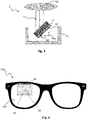
- the linear array 10 may be placed horizontally along the upper edge of the ophthalmic lens 110, as represented in figure 4 , and the scanning mean 40 may be place around the middle of the ophthalmic lens 110.
- the light conducting element 60 may be placed between the linear array 10 and the scanning mean 40, in the upper part of the ophthalmic lens 110.
- the scanning mean may be placed in front of the field of view of the user. In such embodiment, the scanning mean may be configured to move the light beam emitted by the linear array 10 directly on the direction of the eye of the user.
- the projector 1 may be placed around the middle of the ophthalmic lens 110.
- a projector 1 may comprise scanning mean 40 comprising a MEMS mirror so as to direct the light beam on the direction of the eye of the user to display the image. More precisely, the MEMS mirror may be placed in front of the eye of the user without causing discomfort to the user.
- such scanning mean 40 may be about 1 mm, and thus may be integrated in the ophthalmic lens 110 of the head mounted device 100 with transparent connection wires, such as transparent conducting films, or silver nanowires, or any transparent plastic electronic technology used to connect such scanning mean 40 in the middle of an ophthalmic lens 110.
- transparent connection wires such as transparent conducting films, or silver nanowires, or any transparent plastic electronic technology used to connect such scanning mean 40 in the middle of an ophthalmic lens 110.
- Such embodiment is particularly advantageous for augmented reality applications.
- the projector may be removable attachable to a portable device, such as a wrist mounted device, or a mobile phone, or a head mounted device.
- a wrist sensing device such as a watch
- the projector may be located in a frame of the wrist sensing device and configured to project an image towards a surface reflecting light towards an eye of a user or towards an eye of the user.
- the projector may be located in an empty frame of a watch and configured to project the time of the day directly towards the skin of the user under the projector and surrounded by the empty frame.
- the removable projector may be arranged on a head mounted device, such as on a spectacle frame.
- the head mounted device may comprise a connector connected to the removable projector and an optical element intended to be worn near to the eye of the user of the head mounted device.
- the optical element may be a transparent display on which an image may be projected by the removable projector.
- the connector may connect the projector to a command module arranged removable or not on the head mounted device.
- the removable projector may be comprised in a mobile phone and configured for projecting an image instead of displaying such image on the screen of the mobile phone.
- the projector since the projector is removable, the projector may be removed from the mobile phone and worn near the eye of the user, or may be used for projecting an image towards a surface at near distance reflecting light towards an eye of the user, or may be used as a standard screen.
- the projector may be a thin and transparent micro-display easily integrated into a head mounted device.
- the projector may also be used as a wrist display device, for instance a watch display, for multifunction display.
- the projector may comprise a linear array of light sources emitting a light beam and a scanning mean configured to circularly move the light beam.
- the circular movement of the scanning mean allows obtaining a circular display.
- the linear array of light sources allows making a thin one-axe display, configured to display on one axe when the scanning mean is static and to display a circular image when the scanning mean rotates.
- the light sources may be as small as 10 ⁇ m.
- a projector having such light sources allows having a better resolution of the image projected, and a small factor form allowing to integrate the display on a wrist watch or on a near to eye display.
- the projector may further comprise coils and a magnet used to rotate the linear array of light sources.
- the coils may be placed in a circular array at the edge of the display.
- the projector may comprise a connector configured to connect the linear array of light sources and a control system.
- the connector may transfer power supply and data to be displayed.
- the connector may transfer power and data with wireless transmission to the linear array of light sources.
- the linear array of light sources may comprise a reception antenna coupled with an emission antenna, such as a transparent emission antenna, placed on the connector.
- the power and data may be received by the linear array of light sources by high frequency radio signal, such as radio frequency identification (RFID) technology.
- RFID radio frequency identification
Landscapes
- Physics & Mathematics (AREA)
- Engineering & Computer Science (AREA)
- Multimedia (AREA)
- Optics & Photonics (AREA)
- Signal Processing (AREA)
- General Physics & Mathematics (AREA)
- Computer Hardware Design (AREA)
- Microelectronics & Electronic Packaging (AREA)
- Projection Apparatus (AREA)
- Mechanical Optical Scanning Systems (AREA)
Priority Applications (1)
| Application Number | Priority Date | Filing Date | Title |
|---|---|---|---|
| EP21213295.5A EP4012480A1 (de) | 2016-08-08 | 2016-08-08 | Am kopf montiertes gerät mit einem projektor zum projizieren eines bildes |
Applications Claiming Priority (2)
| Application Number | Priority Date | Filing Date | Title |
|---|---|---|---|
| EP16306029.6A EP3281909A1 (de) | 2016-08-08 | 2016-08-08 | Projektor zum projizieren eines bildes auf eine fläche und tragbare vorrichtung mit einem derartigen projektor |
| EP21213295.5A EP4012480A1 (de) | 2016-08-08 | 2016-08-08 | Am kopf montiertes gerät mit einem projektor zum projizieren eines bildes |
Related Parent Applications (1)
| Application Number | Title | Priority Date | Filing Date |
|---|---|---|---|
| EP16306029.6A Division EP3281909A1 (de) | 2016-08-08 | 2016-08-08 | Projektor zum projizieren eines bildes auf eine fläche und tragbare vorrichtung mit einem derartigen projektor |
Publications (1)
| Publication Number | Publication Date |
|---|---|
| EP4012480A1 true EP4012480A1 (de) | 2022-06-15 |
Family
ID=56920669
Family Applications (2)
| Application Number | Title | Priority Date | Filing Date |
|---|---|---|---|
| EP21213295.5A Pending EP4012480A1 (de) | 2016-08-08 | 2016-08-08 | Am kopf montiertes gerät mit einem projektor zum projizieren eines bildes |
| EP16306029.6A Withdrawn EP3281909A1 (de) | 2016-08-08 | 2016-08-08 | Projektor zum projizieren eines bildes auf eine fläche und tragbare vorrichtung mit einem derartigen projektor |
Family Applications After (1)
| Application Number | Title | Priority Date | Filing Date |
|---|---|---|---|
| EP16306029.6A Withdrawn EP3281909A1 (de) | 2016-08-08 | 2016-08-08 | Projektor zum projizieren eines bildes auf eine fläche und tragbare vorrichtung mit einem derartigen projektor |
Country Status (4)
| Country | Link |
|---|---|
| US (1) | US10788661B2 (de) |
| EP (2) | EP4012480A1 (de) |
| CN (1) | CN109071209A (de) |
| WO (1) | WO2018029135A1 (de) |
Families Citing this family (13)
| Publication number | Priority date | Publication date | Assignee | Title |
|---|---|---|---|---|
| US20190019448A1 (en) * | 2017-07-12 | 2019-01-17 | Oculus Vr, Llc | Redundant microleds of multiple rows for compensation of defective microled |
| US11302248B2 (en) | 2019-01-29 | 2022-04-12 | Osram Opto Semiconductors Gmbh | U-led, u-led device, display and method for the same |
| US11271143B2 (en) | 2019-01-29 | 2022-03-08 | Osram Opto Semiconductors Gmbh | μ-LED, μ-LED device, display and method for the same |
| US11156759B2 (en) | 2019-01-29 | 2021-10-26 | Osram Opto Semiconductors Gmbh | μ-LED, μ-LED device, display and method for the same |
| DE112020000561A5 (de) | 2019-01-29 | 2021-12-02 | Osram Opto Semiconductors Gmbh | Videowand, treiberschaltung, ansteuerungen und verfahren derselben |
| WO2020229576A2 (de) | 2019-05-14 | 2020-11-19 | Osram Opto Semiconductors Gmbh | Beleuchtungseinheit, verfahren zur herstellung einer beleuchtungseinheit, konverterelement für ein opto-elektronisches bauelement, strahlungsquelle mit einer led und einem konverterelement, auskoppelstruktur, und optoelektronische vorrichtung |
| KR20210120106A (ko) | 2019-02-11 | 2021-10-06 | 오스람 옵토 세미컨덕터스 게엠베하 | 광전자 부품, 광전자 조립체 및 방법 |
| CN109946906A (zh) * | 2019-04-08 | 2019-06-28 | 深圳康佳电子科技有限公司 | 一种投影显示设备 |
| KR102914276B1 (ko) | 2019-04-23 | 2026-01-16 | 에이엠에스-오스람 인터내셔널 게엠베하 | Led 모듈, led 디스플레이 모듈 및 그 제조 방법 |
| US11538852B2 (en) | 2019-04-23 | 2022-12-27 | Osram Opto Semiconductors Gmbh | μ-LED, μ-LED device, display and method for the same |
| JP7608368B2 (ja) | 2019-05-13 | 2025-01-06 | エイエムエス-オスラム インターナショナル ゲーエムベーハー | マルチチップ用キャリア構造体 |
| CN114144727A (zh) | 2019-05-23 | 2022-03-04 | 奥斯兰姆奥普托半导体股份有限两合公司 | 照明装置、导光装置和方法 |
| CN112596332B (zh) * | 2020-12-23 | 2022-03-11 | 广景视睿科技(深圳)有限公司 | 一种投影系统及投影仪 |
Citations (6)
| Publication number | Priority date | Publication date | Assignee | Title |
|---|---|---|---|---|
| US5715021A (en) * | 1993-02-03 | 1998-02-03 | Nitor | Methods and apparatus for image projection |
| US20130207964A1 (en) * | 2012-02-15 | 2013-08-15 | Rod G. Fleck | Imaging structure with embedded light sources |
| US20130208362A1 (en) * | 2012-02-15 | 2013-08-15 | David D. Bohn | Laser illumination scanning |
| US20150126857A1 (en) * | 2013-11-07 | 2015-05-07 | Samsung Electronics Co., Ltd. | Optical probe and medical imaging apparatus including the same |
| WO2016105283A1 (en) * | 2014-12-26 | 2016-06-30 | Koc University | Near-to-eye display device with moving light sources |
| US20160212888A1 (en) * | 2015-01-20 | 2016-07-21 | Michael Nikkhoo | Metal encased graphite layer heat pipe |
Family Cites Families (11)
| Publication number | Priority date | Publication date | Assignee | Title |
|---|---|---|---|---|
| US10593092B2 (en) * | 1990-12-07 | 2020-03-17 | Dennis J Solomon | Integrated 3D-D2 visual effects display |
| JP2001209342A (ja) * | 2000-01-24 | 2001-08-03 | Matsushita Electric Ind Co Ltd | 映像表示装置 |
| US7133022B2 (en) * | 2001-11-06 | 2006-11-07 | Keyotee, Inc. | Apparatus for image projection |
| US6802451B2 (en) * | 2002-08-07 | 2004-10-12 | Symbol Technologies, Inc. | Scanning actuator assembly for image projection modules, especially in portable instruments |
| US6967758B2 (en) * | 2003-02-04 | 2005-11-22 | Silicon Light Machines Corporation | System and method for sub-pixel electronic alignment |
| KR100814643B1 (ko) * | 2006-07-19 | 2008-03-18 | 주식회사 나노브릭 | 이미지 프로젝션 시스템 및 방법 |
| EP2473880A2 (de) * | 2009-08-31 | 2012-07-11 | 3M Innovative Properties Company | Projektions- und anzeigesystem |
| US8964183B2 (en) * | 2012-05-31 | 2015-02-24 | General Electric Company | Systems and methods for screening of biological samples |
| JP6391952B2 (ja) * | 2014-03-17 | 2018-09-19 | ソニー株式会社 | 表示装置及び光学装置 |
| US10571696B2 (en) * | 2014-12-26 | 2020-02-25 | Cy Vision Inc. | Near-to-eye display device |
| US10299407B2 (en) * | 2015-06-29 | 2019-05-21 | Microsoft Technology Licensing, Llc | Differently oriented layered thermal conduit |
-
2016
- 2016-08-08 EP EP21213295.5A patent/EP4012480A1/de active Pending
- 2016-08-08 EP EP16306029.6A patent/EP3281909A1/de not_active Withdrawn
-
2017
- 2017-08-07 CN CN201780025948.4A patent/CN109071209A/zh active Pending
- 2017-08-07 US US16/098,294 patent/US10788661B2/en active Active
- 2017-08-07 WO PCT/EP2017/069905 patent/WO2018029135A1/en not_active Ceased
Patent Citations (6)
| Publication number | Priority date | Publication date | Assignee | Title |
|---|---|---|---|---|
| US5715021A (en) * | 1993-02-03 | 1998-02-03 | Nitor | Methods and apparatus for image projection |
| US20130207964A1 (en) * | 2012-02-15 | 2013-08-15 | Rod G. Fleck | Imaging structure with embedded light sources |
| US20130208362A1 (en) * | 2012-02-15 | 2013-08-15 | David D. Bohn | Laser illumination scanning |
| US20150126857A1 (en) * | 2013-11-07 | 2015-05-07 | Samsung Electronics Co., Ltd. | Optical probe and medical imaging apparatus including the same |
| WO2016105283A1 (en) * | 2014-12-26 | 2016-06-30 | Koc University | Near-to-eye display device with moving light sources |
| US20160212888A1 (en) * | 2015-01-20 | 2016-07-21 | Michael Nikkhoo | Metal encased graphite layer heat pipe |
Also Published As
| Publication number | Publication date |
|---|---|
| US10788661B2 (en) | 2020-09-29 |
| CN109071209A (zh) | 2018-12-21 |
| WO2018029135A1 (en) | 2018-02-15 |
| US20190137757A1 (en) | 2019-05-09 |
| EP3281909A1 (de) | 2018-02-14 |
Similar Documents
| Publication | Publication Date | Title |
|---|---|---|
| US10788661B2 (en) | Projector configured to project an image towards a surface reflecting light towards an eye of a user and portable device comprising such projector | |
| US9964767B2 (en) | Display with reflected LED micro-display panels | |
| US9151984B2 (en) | Active reflective surfaces | |
| US9684174B2 (en) | Imaging structure with embedded light sources | |
| US9779643B2 (en) | Imaging structure emitter configurations | |
| US20130208362A1 (en) | Laser illumination scanning | |
| CN104345456A (zh) | 显示装置、显示系统以及显示装置的控制方法 | |
| US9848127B2 (en) | System and method for a compact display | |
| US20260126661A1 (en) | Nonintrusive head-mounted device | |
| US10983347B2 (en) | Augmented reality device | |
| CN207396865U (zh) | 头戴显示设备和头戴显示面板 | |
| US12634430B2 (en) | Nonintrusive head-mounted device | |
| US20250159127A1 (en) | Nonintrusive head-mounted device | |
| US12424600B1 (en) | Tiled display system for field of view expansion | |
| JP2018010251A (ja) | 虚像表示装置 | |
| US12578578B2 (en) | Display device and method for driving the same | |
| EP4553563A2 (de) | Reflektierendes lcd-basiertes system für virtuelle realität |
Legal Events
| Date | Code | Title | Description |
|---|---|---|---|
| PUAI | Public reference made under article 153(3) epc to a published international application that has entered the european phase |
Free format text: ORIGINAL CODE: 0009012 |
|
| STAA | Information on the status of an ep patent application or granted ep patent |
Free format text: STATUS: THE APPLICATION HAS BEEN PUBLISHED |
|
| AC | Divisional application: reference to earlier application |
Ref document number: 3281909 Country of ref document: EP Kind code of ref document: P |
|
| AK | Designated contracting states |
Kind code of ref document: A1 Designated state(s): AL AT BE BG CH CY CZ DE DK EE ES FI FR GB GR HR HU IE IS IT LI LT LU LV MC MK MT NL NO PL PT RO RS SE SI SK SM TR |
|
| STAA | Information on the status of an ep patent application or granted ep patent |
Free format text: STATUS: REQUEST FOR EXAMINATION WAS MADE |
|
| 17P | Request for examination filed |
Effective date: 20221207 |
|
| RBV | Designated contracting states (corrected) |
Designated state(s): AL AT BE BG CH CY CZ DE DK EE ES FI FR GB GR HR HU IE IS IT LI LT LU LV MC MK MT NL NO PL PT RO RS SE SI SK SM TR |
|
| P01 | Opt-out of the competence of the unified patent court (upc) registered |
Effective date: 20230525 |
|
| STAA | Information on the status of an ep patent application or granted ep patent |
Free format text: STATUS: EXAMINATION IS IN PROGRESS |
|
| 17Q | First examination report despatched |
Effective date: 20241107 |
|
| GRAP | Despatch of communication of intention to grant a patent |
Free format text: ORIGINAL CODE: EPIDOSNIGR1 |
|
| STAA | Information on the status of an ep patent application or granted ep patent |
Free format text: STATUS: GRANT OF PATENT IS INTENDED |
|
| INTG | Intention to grant announced |
Effective date: 20260320 |
|
| RIN1 | Information on inventor provided before grant (corrected) |
Inventor name: ROUSSEAU, DENIS |