EP4012700B1 - Étui à instruments pour instruments à cordes - Google Patents
Étui à instruments pour instruments à cordes Download PDFInfo
- Publication number
- EP4012700B1 EP4012700B1 EP20213887.1A EP20213887A EP4012700B1 EP 4012700 B1 EP4012700 B1 EP 4012700B1 EP 20213887 A EP20213887 A EP 20213887A EP 4012700 B1 EP4012700 B1 EP 4012700B1
- Authority
- EP
- European Patent Office
- Prior art keywords
- bearing
- instrument
- housing
- neck support
- unit
- Prior art date
- Legal status (The legal status is an assumption and is not a legal conclusion. Google has not performed a legal analysis and makes no representation as to the accuracy of the status listed.)
- Active
Links
Images


Classifications
-
- G—PHYSICS
- G10—MUSICAL INSTRUMENTS; ACOUSTICS
- G10G—REPRESENTATION OF MUSIC; RECORDING MUSIC IN NOTATION FORM; ACCESSORIES FOR MUSIC OR MUSICAL INSTRUMENTS NOT OTHERWISE PROVIDED FOR, e.g. SUPPORTS
- G10G7/00—Other auxiliary devices or accessories, e.g. conductors' batons or separate holders for resin or strings
- G10G7/005—Carrying cases for musical instruments
Definitions
- the invention relates to an instrument case for string instruments.
- An instrument case for accommodating a stringed instrument, with at least one housing, with at least one receiving area delimited by the housing for accommodating an instrument and with at least one neck support module which comprises a neck support unit for supporting an instrument neck, has already been proposed.
- an instrument case for accommodating a stringed instrument is already known, with a housing, with a receiving area delimited by the housing for accommodating an instrument and with at least one neck support module which comprises a neck support unit for supporting an instrument neck.
- the bearing unit is designed as a linear bearing unit.
- a “linear bearing unit” should preferably be understood as a bearing unit that is intended to move an element, such as in particular the neck support unit, between at least two positions linearly, in particular along a bearing axis.
- a linear bearing unit has at least one stationary bearing rail and a bearing carriage that is displaceably guided therein.
- the bearing axis of the bearing unit is preferably aligned in the longitudinal direction of the housing.
- the bearing axis is preferably aligned coaxially with a central axis of the housing that runs in the longitudinal direction of the housing. This allows the bearing unit to be designed particularly simply.
- the first bearing element of the bearing unit is designed as a bearing rail and is firmly connected to the housing.
- a “bearing rail” is preferably understood to mean a linear guide element which is intended to form a bearing track, preferably a straight bearing axis, along which a further element can be linearly displaced on or in the guide rail.
- the bearing rail is intended to have a bearing carriage connected to it in a form-fitting and/or force-fitting manner, wherein the bearing carriage has a degree of freedom relative to the bearing rail at least in one axis, in particular along the bearing axis.
- the bearing element preferably has at least one undercut.
- the second bearing element of the bearing unit is designed as a bearing slide and is connected to the neck support unit.
- a "bearing slide” is preferably understood to mean an element that is intended to be mounted in an axially displaceable manner in a bearing element designed as a bearing rail.
- the bearing element designed as a bearing slide preferably comprises a base body and at least one bearing area attached to the base body.
- the base body is intended to connect elements to be mounted, such as in particular the neck support unit.
- the neck support unit is connected to the base body, preferably directly.
- the first locking element has a toothing and that the second locking element has a corresponding toothing, which engage with one another in a positive locking manner.
- a “toothing” should preferably be understood as a plurality of teeth arranged in a row of teeth. The teeth of the toothing are preferably all designed the same.
- a “corresponding toothing” should preferably be understood as a toothing with at least one tooth, preferably several teeth, which are designed such that they can engage with the teeth of the correspondingly designed toothing in a positive locking manner. This means that the locking elements of the locking unit can be designed particularly simply and secure locking can be ensured by means of the locking unit.
- the locking device has a spring element which is intended to press the first and second locking elements into a locking position.
- a "spring element” is to be understood in particular as an elastic element which has at least one extension and/or a number of windings which can be elastically changed in a normal operating state by at least 10%, in particular by at least 20%, preferably by at least 30% and particularly advantageously by at least 50%, and which in particular generates a counterforce which is dependent on a change in the extension and/or number of windings and is preferably proportional to the change and which counteracts the change.
- the spring element is preferably designed as a compression spring element.
- the spring element is preferably designed as a spiral spring. In principle, it would also be conceivable for the spring element to be designed in another way which appears to be sensible to the person skilled in the art, for example as a Disc spring. This allows for simple, automatic locking of the locking device.
- the locking device has an actuating mechanism by means of which the locking device can be manually adjusted between a locking position and a release position.
- An "actuating mechanism” should preferably be understood as a mechanism that is intended to be actuated by an operator and to transmit an actuating movement to the at least one locking element of the locking device in order to adjust it between its locking position and its release position.
- the at least one locking element of the locking device can be brought from its locking position to its release position by means of the actuating mechanism.
- An adjustment of the locking element from the release position to the locking position preferably takes place automatically.
- a “manual adjustment” should preferably be understood as an adjustment by an operator, for example by exerting a pressure force on an actuating means. In principle, it would also be conceivable that a manual exertion of a pulling force is provided for actuating the actuating mechanism. This makes the locking device particularly easy to operate and therefore adjustment of the neck support module particularly easy.
- the actuating mechanism has at least one actuating means connected to the at least one second locking element and a spring element, against the spring force of which the actuating means can be deflected.
- An "actuating means" should preferably be understood to mean an element that can be deflected between a neutral position and an actuating position by the application of force by an operator.
- the actuating means is preferably designed as a spring-loaded push button that can be deflected from its neutral position to its actuating position by applying a pressure force.
- the actuating means it would also be conceivable for the actuating means to be designed as a pulling element that can be deflected from its neutral position to its actuating position by applying a pulling force.
- the actuating means it would also be conceivable for the actuating means to be designed as a rotating element that can be rotated from its neutral position to its actuating position by applying a torque. This allows the actuating mechanism for operating the locking device to be designed particularly simply.
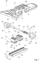
- the Figures 1 to 7 show an embodiment of an instrument case 10 according to the invention.
- the instrument case 10 is formed by a guitar case. In principle, however, another design of the instrument case 10 that appears to be useful to a person skilled in the art would also be conceivable, such as a violin, viola, cello or double bass case.
- the instrument case 10 is intended to accommodate a stringed instrument.
- the instrument case 10 has a housing 12.
- the housing 12 is formed by a shell housing.
- the housing 12 has two housing shells 14.
- the first housing shell 14 is designed as a housing base body.
- the second housing shell not shown in more detail, is designed as a lid.
- the first, lower housing shell 14 is intended to directly accommodate an instrument 16, wherein the lid, not shown in more detail, is intended to close the housing 12.
- the lid can be connected to the first housing shell 14 of the housing 12 via clamp fasteners in a way that is not further visible.
- the instrument case 10 has a receiving area 18 delimited by the housing 12.
- the receiving area 18 is intended to accommodate an instrument 16.
- the instrument 16 is a string instrument.
- the instrument 16 is shown here as a violin as an example. In principle, however, another design of the instrument 16 that appears to be sensible to a specialist would also be conceivable, such as a guitar, cello, viola or double bass.
- the receiving area 18 is delimited by the first housing shell 14 and the cover of the housing 12, which is not further visible. When the housing 12 is closed, the receiving area 18 is essentially closed off.
- the bearing unit 40 has a first bearing element 46.
- the first bearing element 46 is firmly connected to the housing 12.
- the first bearing element 46 is firmly coupled to the base side 20 of the housing 12 for the firm connection to the housing 12.
- the second bearing element 56 is firmly connected to the neck support unit 34.
- the neck support unit 34 has a base formwork 70.
- the base formwork 70 is intended to be coupled to the second bearing element 56.
- the base formwork 70 is designed as a shaped base plate.
- the base formwork 70 forms a construction basis of the neck support unit 34.
- the base formwork 70 preferably forms a basic structure for the neck support element 36 of the neck support unit 34.
- the neck support element 36 is firmly connected to the base formwork 70.
- the neck support element 36 is firmly connected to an upper side of the base formwork 70.
- the neck support element 36 is firmly connected to the base formwork 70 in a material-to-material manner, in particular via an adhesive connection.
- the second locking elements 86, 88 each have a toothing 118, 120.
- the toothings 118, 120 of the second locking elements 86, 88 are designed to correspond to the toothings 114, 116 of the first locking elements 82, 84.
- the toothings 118, 120 of the second locking elements 86, 88 are provided for locking the locking device 80 in such a way that they positively engage in the toothings 114, 116 of the first locking elements 82, 84.
- the toothings 118, 120 of the second locking elements 86, 88 are arranged on elevations arranged on an underside of the locking elements 86, 88 on the sides facing the toothings 114, 116 of the first locking elements 82, 84.
- the spring element 90 is designed in particular as a spiral spring.
- the spring element 90 is arranged between the two second locking elements 86, 88.
- the spring element 90 is placed on the bearing pin 98.
- the spring element 90 is intended to exert a force on the second locking elements 86, 88, which pushes the second locking elements 86, 88 apart from each other outwards.
Landscapes
- Physics & Mathematics (AREA)
- Engineering & Computer Science (AREA)
- Acoustics & Sound (AREA)
- Multimedia (AREA)
- Connection Of Plates (AREA)
- Bearings For Parts Moving Linearly (AREA)
- Purses, Travelling Bags, Baskets, Or Suitcases (AREA)
Claims (7)
- Mallette à instruments pour recevoir un instrument à cordes (16), comprenant un boîtier (12), une zone de réception (18) délimitée par le boîtier (12) pour recevoir un instrument (16) et au moins un module de support de cou (28) qui comprend une unité de support de cou (34) pour supporter un cou d'instrument,
oùle module de support de cou (28) comprend une unité de palier (40) qui présente deux éléments de palier (46, 56) et supporte de manière réglable l'unité de support de cou (34) dans la zone de réception (18),
oùle premier élément de palier (46) de l'unité de palier (40) est réalisé sous forme de rail de palier et est connecté fixement au boîtier (12), le deuxième élément de palier (56) de l'unité de palier (40) étant réalisé sous forme de chariot de palier et étant connecté à l'unité de support de cou (34),où le rail de palier est prévu de telle sorte que le chariot de palier soit connecté à celui-ci par liaison par forme et/ou par force, le chariot de palier présentant un degré de liberté par rapport au rail de palier le long de l'axe de palier (42),où l'unité de palier (40) comprend un dispositif d'arrêt (80) qui est prévu pour bloquer les éléments de palier (46, 56) de l'unité de palier (40) dans différentes positions, le dispositif d'arrêt (80) présentant au moins un premier élément d'arrêt (82, 84) connecté au premier élément de palier (46) et au moins un deuxième élément d'arrêt (86, 88) réalisé de manière correspondante, connecté au deuxième élément de palier (56), caractérisée en ce que le dispositif d'arrêt (80) présente un élément de ressort (90) qui est prévu pour presser les premier et deuxième éléments d'arrêt (82, 84, 86, 88) dans une position d'arrêt. - Mallette à instruments selon la revendication 1, caractérisée en ce que l'unité de palier (40) est réalisée sous forme d'unité de palier linéaire.
- Mallette à instruments selon la revendication 1 ou 2, caractérisée en ce que l'unité de palier (40) est orientée parallèlement à l'axe central (44) du boîtier (12), le premier élément de palier (46) étant couplé fixement au côté de base (20) du boîtier (12) pour la connexion fixe au boîtier (12).
- Mallette à instruments selon la revendication 1, caractérisée en ce que le premier élément d'arrêt (82, 84) présente une denture (114, 116) et en ce que le deuxième élément d'arrêt (86, 88) présente une denture correspondante (118, 120) qui s'engagent l'une dans l'autre par liaison par forme pour un arrêt.
- Mallette à instruments au moins selon la revendication 1, caractérisée en ce que le dispositif d'arrêt (80) présente un mécanisme d'actionnement (92) au moyen duquel le dispositif d'arrêt (80) peut être déplacé manuellement entre une position d'arrêt et une position de libération.
- Mallette à instruments selon la revendication 5 et 3, caractérisée en ce que le mécanisme d'actionnement (92) présente au moins un moyen d'actionnement (94, 96) connecté à l'au moins un deuxième élément d'arrêt (86, 88) et un élément de ressort (90) à l'encontre de la force de ressort duquel le moyen d'actionnement (94, 96) peut être dévié.
- Mallette à instruments selon la revendication 6 et 4, caractérisée en ce que l'élément de ressort (90) du dispositif d'arrêt (80) et l'élément de ressort (90) du mécanisme d'actionnement (92) sont réalisés d'une seule pièce l'un avec l'autre.
Priority Applications (3)
| Application Number | Priority Date | Filing Date | Title |
|---|---|---|---|
| EP20213887.1A EP4012700B1 (fr) | 2020-12-14 | 2020-12-14 | Étui à instruments pour instruments à cordes |
| ES20213887T ES3014008T3 (en) | 2020-12-14 | 2020-12-14 | Instrument bag for stringed instruments |
| US17/544,107 US12125463B2 (en) | 2020-12-14 | 2021-12-07 | Instrument case for string instruments |
Applications Claiming Priority (1)
| Application Number | Priority Date | Filing Date | Title |
|---|---|---|---|
| EP20213887.1A EP4012700B1 (fr) | 2020-12-14 | 2020-12-14 | Étui à instruments pour instruments à cordes |
Publications (3)
| Publication Number | Publication Date |
|---|---|
| EP4012700A1 EP4012700A1 (fr) | 2022-06-15 |
| EP4012700C0 EP4012700C0 (fr) | 2024-11-27 |
| EP4012700B1 true EP4012700B1 (fr) | 2024-11-27 |
Family
ID=73835498
Family Applications (1)
| Application Number | Title | Priority Date | Filing Date |
|---|---|---|---|
| EP20213887.1A Active EP4012700B1 (fr) | 2020-12-14 | 2020-12-14 | Étui à instruments pour instruments à cordes |
Country Status (3)
| Country | Link |
|---|---|
| US (1) | US12125463B2 (fr) |
| EP (1) | EP4012700B1 (fr) |
| ES (1) | ES3014008T3 (fr) |
Families Citing this family (1)
| Publication number | Priority date | Publication date | Assignee | Title |
|---|---|---|---|---|
| US20210082379A1 (en) * | 2019-09-13 | 2021-03-18 | Nathan Owen BROWN | Systems for securing musical instruments inside musical instrument cases |
Family Cites Families (14)
| Publication number | Priority date | Publication date | Assignee | Title |
|---|---|---|---|---|
| US361817A (en) * | 1887-04-26 | Eodolphus t | ||
| US2156910A (en) * | 1936-04-16 | 1939-05-02 | Brooks Morris | Musical instrument carrying case |
| US4190152A (en) * | 1979-02-27 | 1980-02-26 | Reiter Richard L | Musical instrument carrying case |
| US4531632A (en) * | 1984-04-19 | 1985-07-30 | Weber Leroy D | Case for stringed instrument |
| DE9203174U1 (de) * | 1992-03-10 | 1992-08-13 | Dimbath, Wolfgang, 1000 Berlin | Transportgehäuse für Streich- und Zupfinstrumente |
| JP2004061802A (ja) * | 2002-07-29 | 2004-02-26 | Yamaha Corp | 弦楽器用ケース |
| US7290653B2 (en) * | 2004-08-31 | 2007-11-06 | First Act Inc. | Packaged musical instrument |
| US7687701B1 (en) * | 2008-02-11 | 2010-03-30 | Daniel Watson Kushner | Cases for the protection of stringed musical instruments |
| JP2010271698A (ja) * | 2009-04-22 | 2010-12-02 | Sakai Composite Kk | 楽器収容ケース |
| US8978884B1 (en) * | 2011-11-09 | 2015-03-17 | Daniel Watson Kushner | Automatic musical instrument neck support in hybrid cases |
| US9403623B2 (en) * | 2013-07-05 | 2016-08-02 | Craig L. Aaland | Adjustable, reusable packing crate |
| US10596947B2 (en) * | 2017-02-02 | 2020-03-24 | Nifco America Corp. | Cup holder |
| WO2018227013A1 (fr) * | 2017-06-07 | 2018-12-13 | Lewis Ka Hang Cheng | Systèmes et procédés pour caissons inviolables |
| GB201910854D0 (en) * | 2019-07-30 | 2019-09-11 | Crateight Ltd | Apparatus for holding artwork |
-
2020
- 2020-12-14 ES ES20213887T patent/ES3014008T3/es active Active
- 2020-12-14 EP EP20213887.1A patent/EP4012700B1/fr active Active
-
2021
- 2021-12-07 US US17/544,107 patent/US12125463B2/en active Active
Also Published As
| Publication number | Publication date |
|---|---|
| EP4012700C0 (fr) | 2024-11-27 |
| US12125463B2 (en) | 2024-10-22 |
| ES3014008T3 (en) | 2025-04-16 |
| EP4012700A1 (fr) | 2022-06-15 |
| US20220189442A1 (en) | 2022-06-16 |
Similar Documents
| Publication | Publication Date | Title |
|---|---|---|
| EP0647172B1 (fr) | Dispositif de support pour outils | |
| DE4091689C1 (fr) | ||
| DE19615077C2 (de) | Ständer für eine Computer-Tastatur | |
| DE102007036406B3 (de) | Spannweiten-Verlängerungsvorrichtung für ein Spannwerkzeug und Spannwerkzeug-Spannweiten-Verlängerungsvorrichtung-Kombination | |
| DE10234715B4 (de) | Drehbeweglicher Körper mit Entrastelement | |
| DE102014110352B3 (de) | Zentrisch-Spannvorrichtung | |
| EP2470409B1 (fr) | Plateau de transport roulant | |
| DE102016011975B4 (de) | Einstellbarer Aufsatzadapter | |
| EP2791934B1 (fr) | Epaulière pour un instrument de musique | |
| DE102009047705A1 (de) | Zusatzgriff | |
| DE29812635U1 (de) | Verbindungseinrichtung für einen zusammenlegbaren Sonnenschirm | |
| EP4012700B1 (fr) | Étui à instruments pour instruments à cordes | |
| CH686294A5 (de) | Schnellspann-Einrichtung. | |
| DE202008006009U1 (de) | Möbel | |
| EP4382804B1 (fr) | Enveloppe de briquet | |
| EP0611535A1 (fr) | Paroi de confinement d'une surface de rangement ou de support et paroi de séparation montable et ajustable pour cette surface | |
| DE8910878U1 (de) | Einhand-Schnellspannzwinge | |
| DE3224848A1 (de) | Vorrichtung zum gelenkigen, trennbaren verbinden eines segelbrett-mastes und eines gabelbaumes | |
| EP0651966B2 (fr) | Dispositif pour recevoir et maintenir des objets ronds ou polygonaux | |
| DE9110622U1 (de) | Halter für einen Brausekopf | |
| DE102012104974A1 (de) | Vorrichtung zur Verstellung und Positionierung der Rückenlehnenneigung eines Sitzmöbels | |
| DE102005031699A1 (de) | Papierlocher | |
| DE102008047061B4 (de) | Schraubdeckelöffner | |
| DE4415512C1 (de) | Steganordnung für ein Saiteninstrument | |
| DE102008045975A1 (de) | Spannvorrichtung |
Legal Events
| Date | Code | Title | Description |
|---|---|---|---|
| PUAI | Public reference made under article 153(3) epc to a published international application that has entered the european phase |
Free format text: ORIGINAL CODE: 0009012 |
|
| STAA | Information on the status of an ep patent application or granted ep patent |
Free format text: STATUS: THE APPLICATION HAS BEEN PUBLISHED |
|
| AK | Designated contracting states |
Kind code of ref document: A1 Designated state(s): AL AT BE BG CH CY CZ DE DK EE ES FI FR GB GR HR HU IE IS IT LI LT LU LV MC MK MT NL NO PL PT RO RS SE SI SK SM TR |
|
| STAA | Information on the status of an ep patent application or granted ep patent |
Free format text: STATUS: REQUEST FOR EXAMINATION WAS MADE |
|
| 17P | Request for examination filed |
Effective date: 20221207 |
|
| RBV | Designated contracting states (corrected) |
Designated state(s): AL AT BE BG CH CY CZ DE DK EE ES FI FR GB GR HR HU IE IS IT LI LT LU LV MC MK MT NL NO PL PT RO RS SE SI SK SM TR |
|
| STAA | Information on the status of an ep patent application or granted ep patent |
Free format text: STATUS: EXAMINATION IS IN PROGRESS |
|
| 17Q | First examination report despatched |
Effective date: 20230822 |
|
| GRAP | Despatch of communication of intention to grant a patent |
Free format text: ORIGINAL CODE: EPIDOSNIGR1 |
|
| STAA | Information on the status of an ep patent application or granted ep patent |
Free format text: STATUS: GRANT OF PATENT IS INTENDED |
|
| INTG | Intention to grant announced |
Effective date: 20240618 |
|
| GRAS | Grant fee paid |
Free format text: ORIGINAL CODE: EPIDOSNIGR3 |
|
| GRAA | (expected) grant |
Free format text: ORIGINAL CODE: 0009210 |
|
| STAA | Information on the status of an ep patent application or granted ep patent |
Free format text: STATUS: THE PATENT HAS BEEN GRANTED |
|
| AK | Designated contracting states |
Kind code of ref document: B1 Designated state(s): AL AT BE BG CH CY CZ DE DK EE ES FI FR GB GR HR HU IE IS IT LI LT LU LV MC MK MT NL NO PL PT RO RS SE SI SK SM TR |
|
| REG | Reference to a national code |
Ref country code: GB Ref legal event code: FG4D Free format text: NOT ENGLISH |
|
| REG | Reference to a national code |
Ref country code: CH Ref legal event code: EP |
|
| REG | Reference to a national code |
Ref country code: IE Ref legal event code: FG4D Free format text: LANGUAGE OF EP DOCUMENT: GERMAN |
|
| REG | Reference to a national code |
Ref country code: DE Ref legal event code: R096 Ref document number: 502020009828 Country of ref document: DE |
|
| U01 | Request for unitary effect filed |
Effective date: 20241218 |
|
| U07 | Unitary effect registered |
Designated state(s): AT BE BG DE DK EE FI FR IT LT LU LV MT NL PT RO SE SI Effective date: 20250110 |
|
| U20 | Renewal fee for the european patent with unitary effect paid |
Year of fee payment: 5 Effective date: 20241204 |
|
| PG25 | Lapsed in a contracting state [announced via postgrant information from national office to epo] |
Ref country code: HR Free format text: LAPSE BECAUSE OF FAILURE TO SUBMIT A TRANSLATION OF THE DESCRIPTION OR TO PAY THE FEE WITHIN THE PRESCRIBED TIME-LIMIT Effective date: 20241127 Ref country code: IS Free format text: LAPSE BECAUSE OF FAILURE TO SUBMIT A TRANSLATION OF THE DESCRIPTION OR TO PAY THE FEE WITHIN THE PRESCRIBED TIME-LIMIT Effective date: 20250327 |
|
| REG | Reference to a national code |
Ref country code: ES Ref legal event code: FG2A Ref document number: 3014008 Country of ref document: ES Kind code of ref document: T3 Effective date: 20250416 |
|
| PG25 | Lapsed in a contracting state [announced via postgrant information from national office to epo] |
Ref country code: NO Free format text: LAPSE BECAUSE OF FAILURE TO SUBMIT A TRANSLATION OF THE DESCRIPTION OR TO PAY THE FEE WITHIN THE PRESCRIBED TIME-LIMIT Effective date: 20250227 |
|
| PG25 | Lapsed in a contracting state [announced via postgrant information from national office to epo] |
Ref country code: GR Free format text: LAPSE BECAUSE OF FAILURE TO SUBMIT A TRANSLATION OF THE DESCRIPTION OR TO PAY THE FEE WITHIN THE PRESCRIBED TIME-LIMIT Effective date: 20250228 |
|
| PG25 | Lapsed in a contracting state [announced via postgrant information from national office to epo] |
Ref country code: PL Free format text: LAPSE BECAUSE OF FAILURE TO SUBMIT A TRANSLATION OF THE DESCRIPTION OR TO PAY THE FEE WITHIN THE PRESCRIBED TIME-LIMIT Effective date: 20241127 |
|
| PG25 | Lapsed in a contracting state [announced via postgrant information from national office to epo] |
Ref country code: RS Free format text: LAPSE BECAUSE OF FAILURE TO SUBMIT A TRANSLATION OF THE DESCRIPTION OR TO PAY THE FEE WITHIN THE PRESCRIBED TIME-LIMIT Effective date: 20250227 |
|
| PG25 | Lapsed in a contracting state [announced via postgrant information from national office to epo] |
Ref country code: SM Free format text: LAPSE BECAUSE OF FAILURE TO SUBMIT A TRANSLATION OF THE DESCRIPTION OR TO PAY THE FEE WITHIN THE PRESCRIBED TIME-LIMIT Effective date: 20241127 |
|
| PGFP | Annual fee paid to national office [announced via postgrant information from national office to epo] |
Ref country code: CH Payment date: 20250528 Year of fee payment: 5 |
|
| PG25 | Lapsed in a contracting state [announced via postgrant information from national office to epo] |
Ref country code: SK Free format text: LAPSE BECAUSE OF FAILURE TO SUBMIT A TRANSLATION OF THE DESCRIPTION OR TO PAY THE FEE WITHIN THE PRESCRIBED TIME-LIMIT Effective date: 20241127 |
|
| PG25 | Lapsed in a contracting state [announced via postgrant information from national office to epo] |
Ref country code: CZ Free format text: LAPSE BECAUSE OF FAILURE TO SUBMIT A TRANSLATION OF THE DESCRIPTION OR TO PAY THE FEE WITHIN THE PRESCRIBED TIME-LIMIT Effective date: 20241127 |
|
| PG25 | Lapsed in a contracting state [announced via postgrant information from national office to epo] |
Ref country code: MC Free format text: LAPSE BECAUSE OF FAILURE TO SUBMIT A TRANSLATION OF THE DESCRIPTION OR TO PAY THE FEE WITHIN THE PRESCRIBED TIME-LIMIT Effective date: 20241127 |
|
| PLBE | No opposition filed within time limit |
Free format text: ORIGINAL CODE: 0009261 |
|
| STAA | Information on the status of an ep patent application or granted ep patent |
Free format text: STATUS: NO OPPOSITION FILED WITHIN TIME LIMIT |
|
| REG | Reference to a national code |
Ref country code: CH Ref legal event code: L10 Free format text: ST27 STATUS EVENT CODE: U-0-0-L10-L00 (AS PROVIDED BY THE NATIONAL OFFICE) Effective date: 20251008 |
|
| PG25 | Lapsed in a contracting state [announced via postgrant information from national office to epo] |
Ref country code: IE Free format text: LAPSE BECAUSE OF NON-PAYMENT OF DUE FEES Effective date: 20241214 |
|
| 26N | No opposition filed |
Effective date: 20250828 |
|
| REG | Reference to a national code |
Ref country code: CH Ref legal event code: U11 Free format text: ST27 STATUS EVENT CODE: U-0-0-U10-U11 (AS PROVIDED BY THE NATIONAL OFFICE) Effective date: 20260101 |
|
| PGFP | Annual fee paid to national office [announced via postgrant information from national office to epo] |
Ref country code: GB Payment date: 20251218 Year of fee payment: 6 |
|
| U20 | Renewal fee for the european patent with unitary effect paid |
Year of fee payment: 6 Effective date: 20251209 |
|
| PGFP | Annual fee paid to national office [announced via postgrant information from national office to epo] |
Ref country code: ES Payment date: 20260119 Year of fee payment: 6 |