EP4012903A1 - Verfahren und vorrichtung zur herstellung eines stators einer dynamoelektrischen maschine - Google Patents
Verfahren und vorrichtung zur herstellung eines stators einer dynamoelektrischen maschine Download PDFInfo
- Publication number
- EP4012903A1 EP4012903A1 EP20212904.5A EP20212904A EP4012903A1 EP 4012903 A1 EP4012903 A1 EP 4012903A1 EP 20212904 A EP20212904 A EP 20212904A EP 4012903 A1 EP4012903 A1 EP 4012903A1
- Authority
- EP
- European Patent Office
- Prior art keywords
- pole
- members
- last
- engagement
- spatial orientation
- Prior art date
- Legal status (The legal status is an assumption and is not a legal conclusion. Google has not performed a legal analysis and makes no representation as to the accuracy of the status listed.)
- Withdrawn
Links
- 238000000034 method Methods 0.000 title claims abstract description 14
- 230000008859 change Effects 0.000 claims abstract description 6
- 238000006073 displacement reaction Methods 0.000 claims description 59
- 230000006641 stabilisation Effects 0.000 claims description 18
- 238000011105 stabilization Methods 0.000 claims description 18
- 238000004519 manufacturing process Methods 0.000 claims description 10
- 238000011144 upstream manufacturing Methods 0.000 claims description 5
- 238000004804 winding Methods 0.000 description 5
- 230000000087 stabilizing effect Effects 0.000 description 4
- 238000003780 insertion Methods 0.000 description 2
- 230000037431 insertion Effects 0.000 description 2
- 238000012546 transfer Methods 0.000 description 2
- 230000006978 adaptation Effects 0.000 description 1
- 230000003466 anti-cipated effect Effects 0.000 description 1
- 238000005452 bending Methods 0.000 description 1
- 230000005540 biological transmission Effects 0.000 description 1
- 239000004020 conductor Substances 0.000 description 1
- 230000001419 dependent effect Effects 0.000 description 1
- 239000000463 material Substances 0.000 description 1
- 238000012986 modification Methods 0.000 description 1
- 230000004048 modification Effects 0.000 description 1
- 238000011160 research Methods 0.000 description 1
- 230000001360 synchronised effect Effects 0.000 description 1
- 230000007704 transition Effects 0.000 description 1
Images





Classifications
-
- H—ELECTRICITY
- H02—GENERATION; CONVERSION OR DISTRIBUTION OF ELECTRIC POWER
- H02K—DYNAMO-ELECTRIC MACHINES
- H02K15/00—Processes or apparatus specially adapted for manufacturing, assembling, maintaining or repairing of dynamo-electric machines
- H02K15/02—Processes or apparatus specially adapted for manufacturing, assembling, maintaining or repairing of dynamo-electric machines of stator or rotor bodies
- H02K15/021—Magnetic cores
- H02K15/026—Wound cores
-
- H—ELECTRICITY
- H02—GENERATION; CONVERSION OR DISTRIBUTION OF ELECTRIC POWER
- H02K—DYNAMO-ELECTRIC MACHINES
- H02K15/00—Processes or apparatus specially adapted for manufacturing, assembling, maintaining or repairing of dynamo-electric machines
- H02K15/02—Processes or apparatus specially adapted for manufacturing, assembling, maintaining or repairing of dynamo-electric machines of stator or rotor bodies
- H02K15/021—Magnetic cores
- H02K15/022—Magnetic cores with salient poles
-
- H—ELECTRICITY
- H02—GENERATION; CONVERSION OR DISTRIBUTION OF ELECTRIC POWER
- H02K—DYNAMO-ELECTRIC MACHINES
- H02K15/00—Processes or apparatus specially adapted for manufacturing, assembling, maintaining or repairing of dynamo-electric machines
- H02K15/30—Manufacture of winding connections
- H02K15/33—Connecting winding sections; Forming leads; Connecting leads to terminals
-
- H—ELECTRICITY
- H02—GENERATION; CONVERSION OR DISTRIBUTION OF ELECTRIC POWER
- H02K—DYNAMO-ELECTRIC MACHINES
- H02K2213/00—Specific aspects, not otherwise provided for and not covered by codes H02K2201/00 - H02K2211/00
- H02K2213/03—Machines characterised by numerical values, ranges, mathematical expressions or similar information
Definitions
- the present invention relates to a method for producing a stator of a dynamo-electric machine.
- the invention relates to a method for producing an annular stator by assembling together a plurality of pole members wound by an electric wire W for forming respective coils B.
- the invention relates to an apparatus for producing an annular stator of a dynamoelectric machine by assembling together a plurality of pole members wound by an electric wire W for forming respective coils B.
- the pole members are assembled together one next to the other to form a wound core, which is normally a stator component of an electric motor having the field of the pole members directed internally.
- a predetermined number of turns of electric wire needs to be delivered and positioned with accuracy to form the coils.
- the turns of the coils need to be stratified with a required position precision, and the conductor stretches which form the turns need to be regularly positioned.
- connections leads or connection bridges can connect one or more pairs of the coils of the pole members to form a required electric scheme of the stator component.
- winding and assembly of pole members are for example described in EP 1098425 and EP 1629588 , EP3008798 .
- EP 1098425 pliers are provided for holding the pole members. Each plier is moveable on a respective movement device of a transfer table to position the pole members for winding and assembly of a stator. The pole members are secured to the pliers by catches that are assembled on the pliers. Each plier is provided with a shelf for abutment of the lower end of a pole member.
- EP 3008798 illustrates a holder where single poles are positioned for winding and connection leads are disposed for connecting the coils.
- a method for producing an annular stator by assembling together wound poles is also described in US9882457 . More in detail, the method for producing annular stators described in US9882457 provides to insert a plurality of wound poles into a curvilinear slot of a device for moving a row of poles members into an annular assembly of a stator.
- the curvilinear slot has a cross-sectional shape that corresponds to the cross-sectional shape of a wound pole member and comprises a rectilinear insertion section, a spiral transition section and an annular section.
- the row of poles positioned in the rectilinear insertion section is pushed through the section of the curvilinear path into the annular section where an end position is reached in which the row of poles forms the annular configuration.
- the poles are then removed from the annular section using a gripping device and held together in a pressed state.
- connection leads are required between the poles, like is shown with the holder of EP 3008798 , or with connection leads having different connection paths, the assembly of the pole members to form the angular configuration of the stator requires transferring the assembled pole members together with the connection leads to achieve the assembly of the pole members. This transfer becomes a complicated operation in achieving accurate final positioning of the pole members and the connections leads.
- an object of the present invention to provide a method for producing a stator of a dynamo-electric machine by assembling together a plurality of wound poles that is able to overcome the aforementioned drawbacks of the machines of prior art.
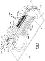
- an apparatus 100 for producing a stator, in particular an annular stator, of a dynamo-electric machine by assembling together a plurality of pole members 10 wound by a wire W forming respective coils B, comprises a first displacement device 20 configured to move a train of poles 5 along a rectilinear trajectory 101.
- the train of poles 5 comprises the plurality of pole members 10 positioned side by side along a predetermined rectilinear trajectory 101 and supported by a plurality of support members 50a-50n.
- the train of poles 5 comprises a first pole member 10a supported by a respective first support member 50a, a predetermined number of intermediate pole members 10i each supported by a respective support member 50i, and a last pole member 10n supported by a respective last support member 50n.
- each pole member 10a, 10i and 10n supported on the respective support members 50a, 50i and 50n are positioned according to a predetermined starting spatial orientation during their movement carried out by a first displacement device 20 along the rectilinear trajectory 101. More precisely, as diagrammatically shown in figures 1 , 2 and 5 , each pole member 10a, 10i and 10n has a respective axis 150a, 150i and 150n, which is directed towards a first direction during the movement of the pole members 10a, 10i and 10n by the first displacement device 20 along the rectilinear trajectory 101.
- the first displacement device 20 can be operated by an endless screw 75 (see figures 1 and 2 ), which can be caused to rotate about its rotation axis 175 in a first rotation direction 176, or in a second opposite rotation direction 176', by a motor, for example an electric motor 90, in particular through a transmission belt 71, in order to move the first displacement device 20 and, therefore, the train of poles 5 in a first moving direction 120, or to move the first displacement device 20 back to a load position for loading a new train of poles (not shown in the figures).
- a motor for example an electric motor 90, in particular through a transmission belt 71, in order to move the first displacement device 20 and, therefore, the train of poles 5 in a first moving direction 120, or to move the first displacement device 20 back to a load position for loading a new train of poles (not shown in the figures).
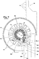
- the apparatus 100 furthermore, comprises a second displacement device 30 (see for example figures 1 , 2 and 5 ), which is configured to cause, at a predetermined passage position P* (see for example figure 5 ) the first pole member 10a and the intermediate pole members 10i supported by respective support members 50a and 50i, at a time to move from the aforementioned predetermined rectilinear trajectory 101 to a predetermined circular trajectory 102 having a centre C.
- a second displacement device 30 see for example figures 1 , 2 and 5
- P* see for example figure 5
- the first pole member 10a and the intermediate pole members 10i supported by respective support members 50a and 50i at a time to move from the aforementioned predetermined rectilinear trajectory 101 to a predetermined circular trajectory 102 having a centre C.
- the second displacement device 30 is configured to move the train of poles 5 along the circular trajectory 102 maintaining the poles 10 radially oriented with respect to the centre C, i.e. with the respective axes 150a and 150i of the pole members, that is maintained directed towards centre C (see for example figure 5 ).
- the second displacement device 30 is configured to move the train of poles 5 along the circular trajectory 102 maintaining the poles 10 radially oriented with respect to the centre C, i.e. with the respective axes 150a and 150i of the pole members, that is maintained directed towards centre C (see for example figure 5 ).
- the poles 10a-10n of the train of poles 5 after all the poles 10a-10n of the train of poles 5 have been positioned along the circular trajectory 102, they are radially pressed in order to achieve a final shape of the annular stator to be assembled.
- each pole member 10a, 10i and 10n coincides with a radial direction with respect to the centre C of the circular trajectory 102 (see respective longitudinal axis 150a, 150i and 150n directed towards centre C at the passage position P*).
- a support element 50i is shown in different instants, in particular 4 different instants (t1,t2,t3,t4).
- the apparatus 100 comprises an additional device 60 for changing the spatial orientation of the last pole member 10n starting from a point of the rectilinear trajectory 101 positioned upstream of passage position P*.
- the last pole member 10n which is supported by the last support member 50n, is shown in different instants, in particular 4 different instants (t1,t2,t3,t4) until it is positioned adjacent to the previous pole member 10n-1 supported by support member 50n-1.
- the last support member 50n is moved to change the predetermined starting spatial orientation of the last pole member 10n (instant t1) in which its longitudinal axis is originally positioned in the first spatial orientation to a final spatial orientation (instant t4) in which the last pole member 10n is radially oriented with the respective longitudinal axis 150n directed towards the centre C of the circular trajectory 102.
- instant t1 the last pole member 10n
- instant t4 a final spatial orientation
- the device 60 for changing gradually causes the spatial orientation of the last pole member 10n to start changing when it reaches a changing position Pc (see figure 6 ) along the rectilinear trajectory 101 (instants t2 and t3) up to be radially oriented with respect to centre C (instant t4) and all the pole members 10a-10n are positioned along the circular trajectory 102.
- the spatial orientation of the last pole member 10n has undergone a sequence of changes that is different from those of the first and the intermediate pole members 10a and 10i to be positioned on the circular trajectory 102. This is particularly necessary to cause the last pole member 10n to be positioned without unwanted interference amongst the first pole member 10a and the last intermediate pole member 10n-1, which precedes the last pole member 10n in the train of pole members 5, on the circular trajectory 102 around centre C that has been chosen.
- the circular trajectory 102 for assembly all the pole members can be chosen in order to have a diameter that is large enough to allow all the pole members 10a, 10i and 10n of the train of poles 5 to be positioned on it one adjacent to another, but to be, at the same time, as small as possible in order to avoid that the pole members 10a, 10i and 10n can move from the correct relative position from each other during assembly operations, in particular when the assembled pole members 10a, 10i and 10n are radially pressed in order to achieve the final shape of the annular stator to be obtained as anticipated above.
- the first displacement device 20 (see for example figures 2 and 5 ) comprises a first plurality of engagement seats 22 positioned side by side and according to a direction parallel to the rectilinear trajectory 101 along which the train of poles 5 is moved by the first displacement device 20.
- the first support member 50a, the intermediate support members 50i and the last support member 50n are provided with respective engagement portions 55a, 55i, 55n. These are arranged to engage with the engagement portion of the adjacent support member 50i-50n forming a chain of support members. More in particular, each support member 50 of the chain of support members is arranged to engage with the adjacent support member 50 free to rotate about a rotation axis 155a, 155i and 155n.
- a plurality of engagement members 51a, 51i, 51n are provided for engaging each engagement portion 55a, 55i and 55n of each support member 50a, 50i, and 50n with the engagement portion 55a, 55i, 55n of the adjacent support member 50a, 50i, 50n.
- the engagement portions 55a, 55i and 55n and the engagement members 51a, 51i and 51n are configured in such a way that each support member 50a, 50i, and 50n is arranged to engage with the adjacent support member 50a, 50i, and 50n free to rotate around a respective rotation axis 151a, 151i and 151n (see figure 3 ).
- each engagement member 51a, 51i and 51n comprises a first engagement portion 52a, 52i and 52n arranged to engage with a respective engagement seat 22of the first displacement device 20 (see for example figure 5 ).
- the chain of support members 50a-50n can be moved by the first displacement device 20 in order to move the train of poles 5 along the rectilinear trajectory 101 in a very accurate way, in particular maintaining each pole member 10a, 10i and 10n at a predetermined distance from an adjacent pole member 10a, 10i and 10n and oriented according to the starting spatial orientation.
- the first engagement portions 52a, 52i and 52n can comprise first rollers, arranged to be free to rotate about respective rotation axes 152a, 152i, 152n.
- each first engagement seat 22 of the first displacement device 20 can be circular-shaped and provided with a respective opening 23 (see for example figure 5 ) through which a respective first engagement portion 52a, 52n and 52i can enter/or exit the respective first engagement seat 22 to be engaged or disengaged.
- At least a part of the support members 50a, 50i and 50n can be provided with first stabilization members 57 (see figure 3 ), for example stabilizing pins 57.
- the stabilizing pins 57 can be arranged to move into a rectilinear groove 27 that is foreseen parallel to the rectilinear trajectory 101 (see figures 2 and 3 ) .
- the stabilizing pins 57 can be arranged to move into a circular groove, not shown in the figures for clarity, that is foreseen coaxial to the circular trajectory 102.
- first stabilizing pins 57 can protrude from the support members 50a, 50i and 50n at the opposite side of the first displacement device 20.
- the second displacement device 30 can be provided with a second plurality of engagement seats 32.
- the engagement members 51a, 51i and 51n can provide respective second engagement portions 52'a, 52'i and 52'n (see also figure 3 ) arranged to engage respective engagement seats 32 of the second plurality of engagement seats 32 of the displacement device 30 in order to move the respective pole members 10a, 10i and 10n along the circular trajectory 102.
- the first engagement portions 52a, 52i and 52n, and the second engagement portions 52'a, 52'i and 52'n are arranged on respective planes parallel with each other.
- the first and the second displacement devices 20 and 30 are configured to engage the support members 50a, 50i and 50n at respective planes parallel with each other. In this way, it is possible to avoid any interference between the first and the second displacement devices 20 and 30, in particular at the passage position P*.
- the second displacement device 30 is provided with a hook-engagement member 35 (see for example figure 1 ) which engages a pin portion 36 (see figures 1 and 3 ) of the first support member 50a starting from the predetermined passage position P* when the second engagement portion 52'a of the first support member 50a engages a respective second engagement seat 32 of the second displacement device 30.
- the second engagement portions 52'a, 52'n and 52'i can comprise second engagement rollers configured to be free to rotate about respective rotation axes 152'a, 152'i and 152'n as shown in figure 3 .
- each second engagement seat 32 of the second displacement device 30 can be circular-shaped and provided with a respective opening 33 through which a respective second engagement portion 52'a, 52'i and 52'n can enter/or exit the respective second engagement seat 32 (see for example figure 5 ).
- the first engagement portion 52a, 52i and 52n and the second engagement portion 52'a, 52'i and 52'n of the same engagement member 51a, 51i and 51n can be coaxial one another and positioned at the same side of the support member 50a, 50i and 50n, but at different heights.
- the first and second displacement devices 20 and 30 are synchronized one another in such a way that at the passage position P* the openings 23 and 33 respectively of a first and a second engagement seats 22 and 32 face each other even though at different heights (see figure 5 ).
- the second displacement device 30 can be a rotating crown, or carousel, peripherally provided with the second plurality of engagement seats 32. More in particular, the second displacement device 30 can be caused to rotate about a rotation axis 130 passing through the centre C by a driving group 80 (shown in figure 2 ), in particular comprising an electric motor, in order to cause the first support member 50a and the intermediate support members 50i engaged at respective engagement seats 32 to be moved along a circular direction coaxial to the circular trajectory 102 along which the respective pole members 10a, 10i and 10n are moved.
- a driving group 80 shown in figure 2
- an electric motor in order to cause the first support member 50a and the intermediate support members 50i engaged at respective engagement seats 32 to be moved along a circular direction coaxial to the circular trajectory 102 along which the respective pole members 10a, 10i and 10n are moved.
- the support members 50 can be provided with respective second stabilization members 58 (shown in figures 3 and 4 ), in particular arranged at the opposite side of the first stabilization members 57 with respect to the support members 50.
- the second stabilization members 58 can be arranged to move into a rectilinear groove, not shown in the figures for clarity, in particular provided with a rectilinear abutment surface.
- the second stabilization members 58 can be arranged to move into a circular groove 39, in particular against a rectilinear abutment surface, in order to stabilize the movement of the support members 50, in particular to avoid tilting (see figure 2 ).
- the device 60 for changing the spatial orientation of the last support member 50n can provide a guide member 65, in particular a guide groove 65, and the last support member 50n can be provided with a third engagement portion 53 (see for example figures 2 , 3 and 4 ) arranged to engage with the guide member 65.
- the third engagement portion 53 is positioned at a different height, in particular at a lower height, with respect to the first engagement portions 52a, 52i and 52n of the engagement members 51a, 51i and 51n.
- the guide member 65 (see for example figure 1 ) comprises a first guide portion 65a parallel to the rectilinear trajectory 101, and a second guide portion 65b, which is shaped, in particular cam-shaped, in such a way that the movement of the first displacement device 20 along the moving direction 120 carried out by the second displacement device 20 causes, when the third engagement portion 53 moves along the second guide portion 65b, the last support member 50n to rotate around the rotation axis 151n of the respective first engagement portion 51n changing the spatial orientation of the longitudinal axis 150n of the last pole member 10n from the predetermined starting spatial orientation to a final spatial orientation in which it is radially oriented with respect to the circular trajectory 102.
- the support members 50a, 50i and 50n can be provided with respective contact portions 54. More in particular, the contact portions 54 of the first and intermediate support members 50a and 50i are positioned at a first distance d1 from a reference height h*, whilst the contact portion 54n of the last support member 50n is positioned at a second distance d2 from the reference height h* different from the first distance d1, for example the second distance d2 can be greater than the first distance d1.
- a first stabilization wall 61 (see figures 1 , 5 , 6 and 8 ) can be provided comprising a first portion 61a parallel to the rectilinear trajectory 101 along which the contact portions 54a, 54i, and 54n of the first, intermediate, and last support members 50a, 50i, and 50n are arranged to move during a first portion of the movement of the first displacement device 20 along the moving direction 120.
- the first stabilization wall 61 (see figure 6 ) comprises a second portion 61b comprising a first part 61'b arranged at the first distance d1 from the reference height h* and parallel to the rectilinear trajectory 101 along which the contact portions 54a, and 54i of the first and intermediate last support members 50a, and 50i are arranged to move during a second portion of the movement of the first displacement device 20 along the moving direction 120 up to reaching the passage position P*.
- the second portion 61b of the first stabilization wall 61 comprises a second part 61"b arranged at the second distance d2 from the reference height h*.
- the second part 61"b is shaped substantially as the second portion 65b of the guide member 65.
- the contact portion 54n of the last support member 50n moves along the second part 61"b of the second portion 61b, and the third engagement portion 53 of the last support member 50n moves along the second guide portion 65b of the guide member 65.
- the contact portions 54a, 54i and 54n moves along a second stabilization wall 62, which has a circular shape concentric to the circular trajectory 102.
- the second stabilization wall 62 is positioned at the opposite side of the second displacement device 30 with respect to the support members 50 (as shown in figure 2 ).
- the second stabilization wall 62 interrupts at a predetermined position of the circular trajectory 102 forming an aperture 63.
- the aperture 63 allows the support members 50a and 50i moved along the rectilinear trajectory 101 to be positioned at the passage position P*.
- the first and the second displacement devices 20 and 30 are configured to move the support members 50 on the same plane, respectively along the rectilinear and circular trajectories 101 and 102.
- the aperture 63 allows also to change the spatial orientation of the last support member 50n.
- each pole 10a, 10i and 10n of the train of poles 5 can be constrained to the adjacent pole member 10a, 10i and 10n by at least a connection lead W' of the wire W having a predetermined length. Therefore, it is fundamental, in this case, to accurately position each pole member 10a, 10i and 10n with respect to the adjacent pole member 10a, 10i and 10n during their movements both along the rectilinear trajectory 101 and the circular trajectory 102, in order to avoid breaking, or other damage to the wire W and or to the connection leads W' connecting the poles.
- circular trajectory 102 for assembly of the poles 10a, 10i and 10n around centre C can be selected to suit the placement of the connection leads without causing the latter to be overlength or too short and become stretched during assembly. More in detail, circular trajectory 102 can be selected where pole members are assembled like has been described in the foregoing with reference to the positioning of the pole members of the train of poles 5 and, in particular, the last pole member 10n, on the circular trajectory 102.
- an exemplary embodiment of an intermediate support member 50i is diagrammatically shown in a perspective, cross-sectional, and plan view, respectively.
- each support member 50a, 50i and 50n can be provide with an holding device 81.
- the holding device 81 can comprise an holding member 82 removably engaged in a slot 12 of the pole 10 (see figure 14 ).
- the holding member 82 is fixed to spring loaded screw 83, which draws holding member 82 against pins 86 (as shown in figures 13 and 14 ) for fixing the pole 10 to the support member 50i thus assuring a correct positioning of the pole members 10i along the rectilinear and circular trajectories 101 and 102, when the support member 50i is moved by the first and second displacement devices 20 and 30, respectively.
Landscapes
- Engineering & Computer Science (AREA)
- Manufacturing & Machinery (AREA)
- Power Engineering (AREA)
- Manufacture Of Motors, Generators (AREA)
Priority Applications (6)
| Application Number | Priority Date | Filing Date | Title |
|---|---|---|---|
| EP20212904.5A EP4012903A1 (de) | 2020-12-09 | 2020-12-09 | Verfahren und vorrichtung zur herstellung eines stators einer dynamoelektrischen maschine |
| CN202180078047.8A CN116529995A (zh) | 2020-12-09 | 2021-12-02 | 用于制造电动发电机的定子的方法和设备 |
| KR1020237022560A KR20230118132A (ko) | 2020-12-09 | 2021-12-02 | 다이나모 발전기의 고정자를 제조하는 방법 및 장치 |
| PCT/IB2021/061253 WO2022123405A2 (en) | 2020-12-09 | 2021-12-02 | Method and apparatus for producing a stator of a dynamo-electric machine |
| US18/265,939 US20240030790A1 (en) | 2020-12-09 | 2021-12-02 | Method and apparatus for producing a stator of a dynamo-electric machine |
| EP21834891.0A EP4260446A2 (de) | 2020-12-09 | 2021-12-02 | Verfahren und vorrichtung zur herstellung eines stators einer dynamoelektrischen maschine |
Applications Claiming Priority (1)
| Application Number | Priority Date | Filing Date | Title |
|---|---|---|---|
| EP20212904.5A EP4012903A1 (de) | 2020-12-09 | 2020-12-09 | Verfahren und vorrichtung zur herstellung eines stators einer dynamoelektrischen maschine |
Publications (1)
| Publication Number | Publication Date |
|---|---|
| EP4012903A1 true EP4012903A1 (de) | 2022-06-15 |
Family
ID=73790025
Family Applications (2)
| Application Number | Title | Priority Date | Filing Date |
|---|---|---|---|
| EP20212904.5A Withdrawn EP4012903A1 (de) | 2020-12-09 | 2020-12-09 | Verfahren und vorrichtung zur herstellung eines stators einer dynamoelektrischen maschine |
| EP21834891.0A Pending EP4260446A2 (de) | 2020-12-09 | 2021-12-02 | Verfahren und vorrichtung zur herstellung eines stators einer dynamoelektrischen maschine |
Family Applications After (1)
| Application Number | Title | Priority Date | Filing Date |
|---|---|---|---|
| EP21834891.0A Pending EP4260446A2 (de) | 2020-12-09 | 2021-12-02 | Verfahren und vorrichtung zur herstellung eines stators einer dynamoelektrischen maschine |
Country Status (5)
| Country | Link |
|---|---|
| US (1) | US20240030790A1 (de) |
| EP (2) | EP4012903A1 (de) |
| KR (1) | KR20230118132A (de) |
| CN (1) | CN116529995A (de) |
| WO (1) | WO2022123405A2 (de) |
Citations (6)
| Publication number | Priority date | Publication date | Assignee | Title |
|---|---|---|---|---|
| EP0652622A2 (de) * | 1993-11-08 | 1995-05-10 | Mitsubishi Denki Kabushiki Kaisha | Rotierender Motor und sein Herstellungsverfahren, Blechkern und sein Herstellungsverfahren |
| EP1098425A2 (de) | 1999-11-03 | 2001-05-09 | AXIS SpA | Wickelmaschine für Komponenten einer dynamo-elektrischen Maschine |
| US20050082919A1 (en) * | 2001-02-01 | 2005-04-21 | Encap Motor Corporation | Motor with stator made from linear core preform |
| EP1629588A1 (de) | 2003-05-22 | 2006-03-01 | AXIS S.p.A. | Vorrichtung und verfahren zum wickeln von spulen für komponenten dynamoelektrischer maschinen |
| EP3008798A2 (de) | 2013-06-11 | 2016-04-20 | ATOP S.p.A. | Vorrichtung und verfahren zum positionieren und aufwickeln von stangenelementen für dynamoelektrische maschinen |
| US9882457B2 (en) | 2011-11-03 | 2018-01-30 | Continental Automotive Gmbh | Method for producing a round stator and rolling device |
Family Cites Families (10)
| Publication number | Priority date | Publication date | Assignee | Title |
|---|---|---|---|---|
| US3577851A (en) * | 1968-03-18 | 1971-05-11 | Lucas Industries Ltd | Method of making dynamoelectric machines |
| US6121711A (en) * | 1993-11-08 | 2000-09-19 | Mitsubishi Denki Kabushiki Kaisha | Rotary motor and production method thereof, and laminated core and production method thereof |
| EP1006645A3 (de) * | 1998-12-04 | 2003-09-24 | PAVESI S.r.l. | Verfahren und Vorrichtung zur Stapelung eines Statorpakets einer dynamoelektrischen Maschine |
| FR2800933B1 (fr) * | 1999-11-10 | 2001-12-28 | Bourgeois R | Procede de fabrication de paquets de toles de forme annulaire |
| JP3730218B2 (ja) * | 2000-08-29 | 2005-12-21 | 三菱電機株式会社 | 積重ステータコアとその製造方法および回転電動機とその製造方法 |
| JP3681631B2 (ja) * | 2000-10-30 | 2005-08-10 | 三菱電機株式会社 | 巻線機および巻線方法 |
| JP4497187B2 (ja) * | 2007-09-21 | 2010-07-07 | 株式会社デンソー | 回転電機の固定子鉄心の製造方法およびその製造方法により製造される回転電機の固定子鉄心 |
| JP4962512B2 (ja) * | 2008-03-12 | 2012-06-27 | 株式会社デンソー | 固定子コイルの製造方法 |
| US8786158B2 (en) * | 2010-08-19 | 2014-07-22 | L. H. Carbide Corporation | Continuously formed annular laminated article and method for its manufacture |
| US9099897B2 (en) * | 2011-09-13 | 2015-08-04 | L.H. Carbide Corporation | Method for connecting end sections of an annular laminated article and articles made therefrom |
-
2020
- 2020-12-09 EP EP20212904.5A patent/EP4012903A1/de not_active Withdrawn
-
2021
- 2021-12-02 EP EP21834891.0A patent/EP4260446A2/de active Pending
- 2021-12-02 US US18/265,939 patent/US20240030790A1/en active Pending
- 2021-12-02 WO PCT/IB2021/061253 patent/WO2022123405A2/en not_active Ceased
- 2021-12-02 KR KR1020237022560A patent/KR20230118132A/ko active Pending
- 2021-12-02 CN CN202180078047.8A patent/CN116529995A/zh active Pending
Patent Citations (6)
| Publication number | Priority date | Publication date | Assignee | Title |
|---|---|---|---|---|
| EP0652622A2 (de) * | 1993-11-08 | 1995-05-10 | Mitsubishi Denki Kabushiki Kaisha | Rotierender Motor und sein Herstellungsverfahren, Blechkern und sein Herstellungsverfahren |
| EP1098425A2 (de) | 1999-11-03 | 2001-05-09 | AXIS SpA | Wickelmaschine für Komponenten einer dynamo-elektrischen Maschine |
| US20050082919A1 (en) * | 2001-02-01 | 2005-04-21 | Encap Motor Corporation | Motor with stator made from linear core preform |
| EP1629588A1 (de) | 2003-05-22 | 2006-03-01 | AXIS S.p.A. | Vorrichtung und verfahren zum wickeln von spulen für komponenten dynamoelektrischer maschinen |
| US9882457B2 (en) | 2011-11-03 | 2018-01-30 | Continental Automotive Gmbh | Method for producing a round stator and rolling device |
| EP3008798A2 (de) | 2013-06-11 | 2016-04-20 | ATOP S.p.A. | Vorrichtung und verfahren zum positionieren und aufwickeln von stangenelementen für dynamoelektrische maschinen |
Also Published As
| Publication number | Publication date |
|---|---|
| WO2022123405A3 (en) | 2022-07-21 |
| EP4260446A2 (de) | 2023-10-18 |
| KR20230118132A (ko) | 2023-08-10 |
| WO2022123405A2 (en) | 2022-06-16 |
| CN116529995A (zh) | 2023-08-01 |
| US20240030790A1 (en) | 2024-01-25 |
Similar Documents
| Publication | Publication Date | Title |
|---|---|---|
| US10742101B2 (en) | Insertion apparatus which inserts U-shaped conductors | |
| US12237732B2 (en) | Device for positioning ends of at least first pair of legs of hairpin conductors | |
| US8726493B2 (en) | Clamping system of special conductors for a stator or rotor bar winding for an electric machine | |
| US8302286B2 (en) | Method for manufacturing a stator winding | |
| US9444315B2 (en) | Arrangement apparatus and arrangement method | |
| CN103518316B (zh) | 在焊接前使电机芯部中的线圈构件的导体对准的设备和方法 | |
| US7311284B2 (en) | Coil forming method and coil forming device | |
| JP5795148B2 (ja) | コイル挿入装置 | |
| JP4327486B2 (ja) | 回転電機のコイル用のセグメントの成形装置、セグメントの成形方法及びそれを用いたセグメント | |
| US20130162072A1 (en) | Method for manufacturing stator, apparatus for manufacturing stator, and stator | |
| US20190103792A1 (en) | Alignment method and alignment device | |
| US12249881B2 (en) | Manufacturing system for manufacturing a stator with bar conductors | |
| EP3118978A1 (de) | Statorherstellungsvorrichtung und herstellungsverfahren | |
| US11705792B2 (en) | Coil insertion device and coil insertion method | |
| JP5633967B2 (ja) | コイル挿入方法およびコイル挿入装置 | |
| US8468686B2 (en) | Apparatus for terminating leads of plural wires in dynamo electric machine core | |
| US20120160950A1 (en) | Winding device | |
| US20180316251A1 (en) | Apparatus and method for producing stators of dynamo electric machines formed from an assembly of pole segments | |
| EP1609231B1 (de) | Verfahren und gerät zur einführung von spulenanschlussen | |
| KR20260012793A (ko) | 모터 고정자의 슬롯 내로 이후 이송될 헤어핀을 수용하기 위한 코움 디바이스 및 사용 방법 | |
| EP2144352B1 (de) | Vorrichtung und verfahren zum einfügen von spulen und abdeckkeilen in die schlitze von kernen dynamoelektrischer maschinen | |
| US20240030790A1 (en) | Method and apparatus for producing a stator of a dynamo-electric machine | |
| EP2562916A1 (de) | Stator und verfahren zur herstellung des stators | |
| US20240396414A1 (en) | Device, machine and method for producing a final configuration of conductor elements | |
| JP5672207B2 (ja) | 分布巻きコイルを用いた固定子の製造方法 |
Legal Events
| Date | Code | Title | Description |
|---|---|---|---|
| PUAI | Public reference made under article 153(3) epc to a published international application that has entered the european phase |
Free format text: ORIGINAL CODE: 0009012 |
|
| STAA | Information on the status of an ep patent application or granted ep patent |
Free format text: STATUS: THE APPLICATION HAS BEEN PUBLISHED |
|
| AK | Designated contracting states |
Kind code of ref document: A1 Designated state(s): AL AT BE BG CH CY CZ DE DK EE ES FI FR GB GR HR HU IE IS IT LI LT LU LV MC MK MT NL NO PL PT RO RS SE SI SK SM TR |
|
| STAA | Information on the status of an ep patent application or granted ep patent |
Free format text: STATUS: THE APPLICATION IS DEEMED TO BE WITHDRAWN |
|
| 18D | Application deemed to be withdrawn |
Effective date: 20221216 |