EP4012908A1 - Convertisseur pfc et cc cc intégré pour un double bus cc pour une application asi en ligne - Google Patents
Convertisseur pfc et cc cc intégré pour un double bus cc pour une application asi en ligne Download PDFInfo
- Publication number
- EP4012908A1 EP4012908A1 EP21208610.2A EP21208610A EP4012908A1 EP 4012908 A1 EP4012908 A1 EP 4012908A1 EP 21208610 A EP21208610 A EP 21208610A EP 4012908 A1 EP4012908 A1 EP 4012908A1
- Authority
- EP
- European Patent Office
- Prior art keywords
- power
- input
- converter
- backup
- ups
- Prior art date
- Legal status (The legal status is an assumption and is not a legal conclusion. Google has not performed a legal analysis and makes no representation as to the accuracy of the status listed.)
- Pending
Links
Images



Classifications
-
- H—ELECTRICITY
- H02—GENERATION; CONVERSION OR DISTRIBUTION OF ELECTRIC POWER
- H02M—APPARATUS FOR CONVERSION BETWEEN AC AND AC, BETWEEN AC AND DC, OR BETWEEN DC AND DC, AND FOR USE WITH MAINS OR SIMILAR POWER SUPPLY SYSTEMS; CONVERSION OF DC OR AC INPUT POWER INTO SURGE OUTPUT POWER; CONTROL OR REGULATION THEREOF
- H02M1/00—Details of apparatus for conversion
- H02M1/10—Arrangements incorporating converting means for enabling loads to be operated at will from different kinds of power supplies, e.g. from AC or DC
-
- H—ELECTRICITY
- H02—GENERATION; CONVERSION OR DISTRIBUTION OF ELECTRIC POWER
- H02J—ELECTRIC POWER NETWORKS; CIRCUIT ARRANGEMENTS OR SYSTEMS FOR SUPPLYING OR DISTRIBUTING ELECTRIC POWER; SYSTEMS FOR STORING ELECTRIC ENERGY
- H02J9/00—Circuit arrangements for emergency or stand-by power supply, e.g. for emergency lighting
- H02J9/04—Circuit arrangements for emergency or stand-by power supply, e.g. for emergency lighting in which the distribution system is disconnected from the normal source and connected to a standby source
- H02J9/06—Circuit arrangements for emergency or stand-by power supply, e.g. for emergency lighting in which the distribution system is disconnected from the normal source and connected to a standby source with automatic change-over, e.g. UPS systems
- H02J9/061—Circuit arrangements for emergency or stand-by power supply, e.g. for emergency lighting in which the distribution system is disconnected from the normal source and connected to a standby source with automatic change-over, e.g. UPS systems for DC powered loads
-
- H—ELECTRICITY
- H02—GENERATION; CONVERSION OR DISTRIBUTION OF ELECTRIC POWER
- H02J—ELECTRIC POWER NETWORKS; CIRCUIT ARRANGEMENTS OR SYSTEMS FOR SUPPLYING OR DISTRIBUTING ELECTRIC POWER; SYSTEMS FOR STORING ELECTRIC ENERGY
- H02J9/00—Circuit arrangements for emergency or stand-by power supply, e.g. for emergency lighting
- H02J9/04—Circuit arrangements for emergency or stand-by power supply, e.g. for emergency lighting in which the distribution system is disconnected from the normal source and connected to a standby source
- H02J9/06—Circuit arrangements for emergency or stand-by power supply, e.g. for emergency lighting in which the distribution system is disconnected from the normal source and connected to a standby source with automatic change-over, e.g. UPS systems
- H02J9/068—Electronic means for switching from one power supply to another power supply, e.g. to avoid parallel connection
-
- H—ELECTRICITY
- H02—GENERATION; CONVERSION OR DISTRIBUTION OF ELECTRIC POWER
- H02M—APPARATUS FOR CONVERSION BETWEEN AC AND AC, BETWEEN AC AND DC, OR BETWEEN DC AND DC, AND FOR USE WITH MAINS OR SIMILAR POWER SUPPLY SYSTEMS; CONVERSION OF DC OR AC INPUT POWER INTO SURGE OUTPUT POWER; CONTROL OR REGULATION THEREOF
- H02M1/00—Details of apparatus for conversion
- H02M1/0083—Converters characterised by their input or output configuration
-
- H—ELECTRICITY
- H02—GENERATION; CONVERSION OR DISTRIBUTION OF ELECTRIC POWER
- H02M—APPARATUS FOR CONVERSION BETWEEN AC AND AC, BETWEEN AC AND DC, OR BETWEEN DC AND DC, AND FOR USE WITH MAINS OR SIMILAR POWER SUPPLY SYSTEMS; CONVERSION OF DC OR AC INPUT POWER INTO SURGE OUTPUT POWER; CONTROL OR REGULATION THEREOF
- H02M1/00—Details of apparatus for conversion
- H02M1/42—Circuits or arrangements for compensating for or adjusting power factor in converters or inverters
- H02M1/4208—Arrangements for improving power factor of AC input
- H02M1/4225—Arrangements for improving power factor of AC input using a non-isolated boost converter
-
- H—ELECTRICITY
- H02—GENERATION; CONVERSION OR DISTRIBUTION OF ELECTRIC POWER
- H02M—APPARATUS FOR CONVERSION BETWEEN AC AND AC, BETWEEN AC AND DC, OR BETWEEN DC AND DC, AND FOR USE WITH MAINS OR SIMILAR POWER SUPPLY SYSTEMS; CONVERSION OF DC OR AC INPUT POWER INTO SURGE OUTPUT POWER; CONTROL OR REGULATION THEREOF
- H02M3/00—Conversion of DC power input into DC power output
- H02M3/02—Conversion of DC power input into DC power output without intermediate conversion into AC
- H02M3/04—Conversion of DC power input into DC power output without intermediate conversion into AC by static converters
- H02M3/10—Conversion of DC power input into DC power output without intermediate conversion into AC by static converters using discharge tubes with control electrode or semiconductor devices with control electrode
- H02M3/145—Conversion of DC power input into DC power output without intermediate conversion into AC by static converters using discharge tubes with control electrode or semiconductor devices with control electrode using devices of a triode or transistor type requiring continuous application of a control signal
- H02M3/155—Conversion of DC power input into DC power output without intermediate conversion into AC by static converters using discharge tubes with control electrode or semiconductor devices with control electrode using devices of a triode or transistor type requiring continuous application of a control signal using semiconductor devices only
- H02M3/1557—Single ended primary inductor converters [SEPIC]
-
- H—ELECTRICITY
- H02—GENERATION; CONVERSION OR DISTRIBUTION OF ELECTRIC POWER
- H02M—APPARATUS FOR CONVERSION BETWEEN AC AND AC, BETWEEN AC AND DC, OR BETWEEN DC AND DC, AND FOR USE WITH MAINS OR SIMILAR POWER SUPPLY SYSTEMS; CONVERSION OF DC OR AC INPUT POWER INTO SURGE OUTPUT POWER; CONTROL OR REGULATION THEREOF
- H02M3/00—Conversion of DC power input into DC power output
- H02M3/02—Conversion of DC power input into DC power output without intermediate conversion into AC
- H02M3/04—Conversion of DC power input into DC power output without intermediate conversion into AC by static converters
- H02M3/10—Conversion of DC power input into DC power output without intermediate conversion into AC by static converters using discharge tubes with control electrode or semiconductor devices with control electrode
- H02M3/145—Conversion of DC power input into DC power output without intermediate conversion into AC by static converters using discharge tubes with control electrode or semiconductor devices with control electrode using devices of a triode or transistor type requiring continuous application of a control signal
- H02M3/155—Conversion of DC power input into DC power output without intermediate conversion into AC by static converters using discharge tubes with control electrode or semiconductor devices with control electrode using devices of a triode or transistor type requiring continuous application of a control signal using semiconductor devices only
- H02M3/156—Conversion of DC power input into DC power output without intermediate conversion into AC by static converters using discharge tubes with control electrode or semiconductor devices with control electrode using devices of a triode or transistor type requiring continuous application of a control signal using semiconductor devices only with automatic control of output voltage or current, e.g. switching regulators
- H02M3/158—Conversion of DC power input into DC power output without intermediate conversion into AC by static converters using discharge tubes with control electrode or semiconductor devices with control electrode using devices of a triode or transistor type requiring continuous application of a control signal using semiconductor devices only with automatic control of output voltage or current, e.g. switching regulators including plural semiconductor devices as final control devices for a single load
- H02M3/1582—Buck-boost converters
-
- H—ELECTRICITY
- H02—GENERATION; CONVERSION OR DISTRIBUTION OF ELECTRIC POWER
- H02M—APPARATUS FOR CONVERSION BETWEEN AC AND AC, BETWEEN AC AND DC, OR BETWEEN DC AND DC, AND FOR USE WITH MAINS OR SIMILAR POWER SUPPLY SYSTEMS; CONVERSION OF DC OR AC INPUT POWER INTO SURGE OUTPUT POWER; CONTROL OR REGULATION THEREOF
- H02M5/00—Conversion of AC power input into AC power output, e.g. for change of voltage, for change of frequency, for change of number of phases
- H02M5/40—Conversion of AC power input into AC power output, e.g. for change of voltage, for change of frequency, for change of number of phases with intermediate conversion into DC
- H02M5/42—Conversion of AC power input into AC power output, e.g. for change of voltage, for change of frequency, for change of number of phases with intermediate conversion into DC by static converters
- H02M5/44—Conversion of AC power input into AC power output, e.g. for change of voltage, for change of frequency, for change of number of phases with intermediate conversion into DC by static converters using discharge tubes or semiconductor devices to convert the intermediate DC into AC
- H02M5/453—Conversion of AC power input into AC power output, e.g. for change of voltage, for change of frequency, for change of number of phases with intermediate conversion into DC by static converters using discharge tubes or semiconductor devices to convert the intermediate DC into AC using devices of a triode or transistor type requiring continuous application of a control signal
- H02M5/458—Conversion of AC power input into AC power output, e.g. for change of voltage, for change of frequency, for change of number of phases with intermediate conversion into DC by static converters using discharge tubes or semiconductor devices to convert the intermediate DC into AC using devices of a triode or transistor type requiring continuous application of a control signal using semiconductor devices only
-
- Y—GENERAL TAGGING OF NEW TECHNOLOGICAL DEVELOPMENTS; GENERAL TAGGING OF CROSS-SECTIONAL TECHNOLOGIES SPANNING OVER SEVERAL SECTIONS OF THE IPC; TECHNICAL SUBJECTS COVERED BY FORMER USPC CROSS-REFERENCE ART COLLECTIONS [XRACs] AND DIGESTS
- Y02—TECHNOLOGIES OR APPLICATIONS FOR MITIGATION OR ADAPTATION AGAINST CLIMATE CHANGE
- Y02B—CLIMATE CHANGE MITIGATION TECHNOLOGIES RELATED TO BUILDINGS, e.g. HOUSING, HOUSE APPLIANCES OR RELATED END-USER APPLICATIONS
- Y02B70/00—Technologies for an efficient end-user side electric power management and consumption
- Y02B70/10—Technologies improving the efficiency by using switched-mode power supplies [SMPS], i.e. efficient power electronics conversion e.g. power factor correction or reduction of losses in power supplies or efficient standby modes
Definitions
- Embodiments of this disclosure relate generally to power conversion, and more particularly, to AC-DC power conversion in an uninterruptible power supply.
- UPS uninterruptible power supply
- Typical loads include computer systems, but other loads, such as heating/cooling/ventilation systems, lighting systems, network switches and routers, and security data center management systems may also receive backup power between 1 and 20 kVA for several hours.
- the UPS includes an input configured to receive input AC power, a backup power input configured to receive backup DC power having a first voltage level from a backup power source, a converter configured to convert the input AC power from the input and the backup DC power from the backup power input into DC power having a second voltage level, the converter including an input selection circuit configured to selectively couple the converter to the input and the backup power input, an inductor, a first converter switch configured to couple a first end of the inductor to a neutral connection, and a second converter switch configured to couple a second end of the inductor to the backup power input via the input selection circuit.
- the UPS includes an input configured to receive input AC power, a backup power input configured to receive backup DC power having a first voltage level from a backup power source, a converter configured to convert the input AC power from the input and the backup DC power from the backup power input into DC power having a second voltage level, the converter including an input selection circuit configured to selectively couple the converter to the input and the backup power input, an inductor, a first converter switch configured
- the UPS includes an output configured to provide output AC power to a load, and an inverter coupled to the output and configured to convert the DC power having the second voltage level into the output AC power and provide the output AC power to the output.
- the UPS includes a DC bus coupled to the converter and configured to receive the DC power having the second voltage level, and a controller coupled to at least the converter and configured to operate the first converter switch in a first mode of operation to provide DC power having the second voltage level to the DC bus derived from the input AC power and the first and second converter switches in a second mode of operation to provide DC power having the second voltage level to the DC bus derived from the backup DC power.
- the controller is configured to monitor the input AC power, operate, in response to a determination that the input AC power is acceptable, the UPS in the first mode of operation, and operate, in response to a determination that the input AC power is unacceptable, the UPS in the second mode of operation.
- the controller is configured to control the input selection circuit to couple the input to the converter during the first mode of operation.
- the controller is configured to control the input selection circuit to couple the backup power input to the converter during the second mode of operation.
- the first converter switch is a bidirectional switch circuit including a first switch and a second switch coupled in series.
- the first and second switches of the first converter switch each have a drain, a gate, and a source, the drain of the first switch being coupled to the first end of the inductor, the gate of the first switch being coupled to the gate of the second switch, the source of the first switch being coupled to the source of the second switch, and the drain of the second switch being coupled to the neutral connection.
- the converter includes a first output coupled to a first rail of the DC bus, a second output coupled to a second rail of the DC bus, and a first diode having an anode coupled to the second output and a cathode coupled to the second converter switch and the input selection circuit.
- the converter includes a first capacitor coupled between the first output and the neutral connection, a second capacitor coupled between the second output and the neutral connection, a second diode having a cathode coupled to the first capacitor and the first output, and a third diode having an anode coupled to the second capacitor and the second output.
- the first end of the inductor is coupled to an anode of the second diode and a cathode of the third diode.
- the inductor, the second diode, the first capacitor, and the first converter switch are configured to operate as a Power Factor Correction (PFC) boost converter during a positive half cycle of the input AC power in the first mode of operation.
- the inductor, the third diode, the second capacitor, and the first converter switch are configured to operate as a Power Factor Correction (PFC) boost converter during a negative half cycle of the input AC power in the first mode of operation.
- PFC Power Factor Correction
- the inductor, the second diode, the first capacitor, the first converter switch, and the second converter switch are configured to operate as a boost converter during a positive half cycle of the output AC power in the second mode of operation.
- the inductor, the first diode, the second capacitor, the first converter switch, and the second converter switch are configured to operate as a buck-boost converter during a negative half cycle of the output AC power in the second mode of operation.
- a negative terminal of the backup power source is configured to be connected to the neutral connection.
- Another aspect of the present invention is directed to a non-transitory computer-readable medium storing thereon sequences of computer-executable instructions for controlling an Uninterruptible Power Supply (UPS) including an input configured to receive input AC power, a backup power input configured to receive backup DC power having a first voltage level from a backup power source, and a converter including an inductor coupled to the input and the backup power input via an input selection circuit, the converter being configured to convert the input AC power from the input and the backup DC power from the backup power input into DC power having a second voltage level.
- UPS Uninterruptible Power Supply
- the sequences of computer-executable instructions include instructions that instruct at least one processor to monitor the input AC power received at the input, operate, in response to a determination that the input AC power is acceptable, the UPS in a first mode of operation to provide DC power having the second voltage level derived from the input AC power by operating a first converter switch configured to couple a first end of the inductor to a neutral connection, and operate, in response to a determination that the input AC power is unacceptable, the UPS in a second mode of operation to provide DC power having the second voltage level derived from the backup DC power by operating the first converter switch and a second converter switch configured to couple a second end of the inductor to the backup power input via the input selection circuit.
- the sequences of instructions include instructions that cause the at least one processor to control the input selection circuit to couple the input to the inductor during the first mode of operation, and control the input selection circuit to couple the backup power input to the inductor during the second mode of operation.
- the sequences of instructions include instructions that cause the at least one processor to operate the converter as a Power Factor Correction (PFC) boost converter in the first mode of operation.
- the sequences of instructions include instructions that cause the at least one processor to operate, during a positive half cycle of the output AC power, the converter as a boost converter in the second mode of operation.
- the sequences of instructions include instructions that cause the at least one processor to operate, during a negative half cycle of the output AC power, the converter as a buck-boost converter in the second mode of operation.
- references to "or” may be construed as inclusive so that any terms described using “or” may indicate any of a single, more than one, and all of the described terms.
- the term usage in the incorporated references is supplementary to that of this document; for irreconcilable inconsistencies, the term usage in this document controls.
- UPS uninterruptible power supplies
- An online UPS rectifies input AC power provided by an electric utility using a Power Factor Correction converter circuit (PFC) to provide DC power to at least one DC bus.
- PFC Power Factor Correction converter circuit
- the rectified DC power on the DC bus(es) may be used to charge a battery while mains power is available. In the absence of mains power, the battery discharges and provides DC power to the DC bus(es). From the DC power on the DC bus(es), an inverter generates an AC output voltage that is provided to a load.
- PFC Power Factor Correction converter circuit
- UPS's may also operate in a bypass mode where unconditioned power with basic protection is provided directly from an AC power source to a load via a bypass line.
- such online UPS topologies include a PFC converter to provide DC power to the DC bus when AC mains is available and a separate DC/DC converter to provide DC power to the DC bus from the battery when AC mains is unavailable.
- these online UPS topologies often have a high component count which can result in increased cost, increased system complexity, and reduced power density.
- such UPS topologies often include components which are unused or idle during at least one mode of operation of the online UPS.
- the topology includes a converter selectively coupled to an input configured to receive input AC power and a backup power input configured to receive backup DC power.
- the converter is configured to provide DC power to a DC bus of the UPS derived from either the input AC power or the backup DC power.
- the improved online UPS topology may have a reduced component count, increasing the power density of the UPS and reducing cost.
- FIG. 1 is a block diagram of one embodiment of an online UPS 100 that can provide regulated power from input AC power received at an input 102, as well as back-up DC power from a backup power source 112 (e.g., a battery), to an output 110.
- a backup power source 112 e.g., a battery
- the backup power source 112 may be included in the UPS 100; however, in other examples, the backup power source 112 may be external to the UPS 100.
- the UPS 100 includes a converter 104, a DC bus 106, an inverter 108, and a controller 114 for controlling the converter 104 and the inverter 108.
- the DC bus 106 is coupled between the converter 104 and the inverter 108.
- the input 102 is configured to receive input AC power having an input voltage level from an AC power source.
- the controller 114 monitors the input AC power received by the input 102 and is configured to operate the UPS 100 in different modes of operation based on the status of the input AC power received by the input 102. When AC power provided to the input 102 is acceptable (i.e., above an input power quality threshold), the controller 114 operates the UPS 100 in an online mode of operation.
- AC power from the input 102 is provided to the converter 104.
- the controller 114 operates the converter 104 to convert the AC power into DC power and provide the DC power to the DC bus 106.
- DC power from the DC bus 106 is provided to the inverter 108.
- DC power from the DC bus 106 may be provided to the battery 112 for charging, either directly from the converter 104 or via a separate DC/DC converter (e.g., a charger).
- the controller 114 operates the inverter 108 to convert the DC power into regulated AC power and provide the regulated AC power to a load coupled to the output 110.
- the controller 114 When AC power provided to the input 102 is not acceptable (i.e., below an input power quality threshold), the controller 114 operates the UPS 100 in a backup mode of operation. In the backup mode of operation, DC power from the backup power source 112 is provided to the DC bus 106.
- the inverter 108 receives the DC power from the DC bus 106, and the controller 114 operates the inverter 108 to convert the DC power from the DC bus 106 into regulated AC power and provide the regulated AC power to the output 110.
- the converter 104 may include a PFC converter configured to provide DC power to the DC bus 106 derived from the input AC power during the online mode of operation and a separate DC/DC converter configured to provide DC power to the DC bus 106 derived from the backup DC power during the backup mode of operation. While such topologies can be utilized to provide uninterrupted power, the use of multiple converters requires the use of additional components, increasing cost and complexity while the reducing power density. As such, it may be advantageous to configure the converter 104 as a single multi-function converter capable of providing DC power to the DC bus 106 derived from either the input AC power or the backup DC power.
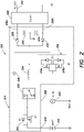
- FIG. 2 is a schematic diagram of a UPS topology 200 according to aspects described herein.
- the UPS topology 200 corresponds to the UPS 100 of FIG. 1 .
- the UPS topology 200 includes an input 202 coupled to an input AC source 203, a converter 204, a DC bus 206a, 206b (referred to collectively herein as DC bus 206), an inverter 208, and an output 210.
- the UPS topology 200 includes a backup power source 212 (e.g., a battery) coupled to a backup power input 214.
- the backup power source 212 may be included in the UPS topology 200; however, in other examples, the backup power source 212 may be separate from the UPS topology 200.
- the converter 204 includes a first converter switch 216, a second converter switch 218, an input selection circuit 220, an inductor 224, a first diode 226, a second diode 228, a third diode 230, a first capacitor 232, and a second capacitor 234.
- the first and second converter switches 216, 218 are Metal-Oxide-Semiconductor Field-Effect Transistors (MOSFETs); however, in other embodiments, different types of switches or transistors can be utilized (e.g., Insulated-Gate Bipolar Transistors (IGBTs)).
- each switch has a gate, a drain, and a source. In this context, “drain” may refer to any device terminal at which current enters the switch. Likewise, “source” may refer to any device terminal at which current exits the switch.
- the first converter switch 216 is a bidirectional switch circuit including a first switch 216a coupled in series with a second switch 216b.
- the source of the first switch 216a is coupled to the drain of the second switch 216b and the drain of the second switch 216b is coupled to neutral.
- the first converter switch 216 can be turned on (i.e., closed) by turning on both the first switch 216a and the second switch 216b to provide a bi-directional conduction path.
- the first converter switch 216 can be turned off (i.e., opened) by turning off both the first switch 216a and the second switch 216b.
- the input selection circuit 220 is configured to couple the inductor 224 to one of the input 202 or the backup power input 214 (via the second converter switch 218).
- a first end of the inductor 224 is coupled to the drain of the first switch 216a, an anode of the second diode 228 and a cathode of the third diode 230 and a second end of the inductor 224 is coupled to the input selection circuit 220.
- a first end of the first capacitor 232 is coupled to a cathode of the second diode 228 and the first rail 206a of the DC bus 206 and at a second end to neutral.
- the second capacitor 234 is coupled at a first end to an anode of the first diode 226, an anode of the third diode 230, and the second rail of the DC bus 206b and at a second end to neutral.
- a cathode of the first diode 226 is coupled to the input selection circuit 220 and the source of the second converter switch 218.
- the drain of the second converter switch 218 is coupled to the backup power source 212.
- the UPS topology 200 can be operated in various modes of operation.
- the input selection circuit 220 is controlled to couple the second end of the inductor 224 to the input 202 such that AC power from the input 202 is provided to the converter 204.
- the converter 204 converts the AC power into DC power having the DC bus voltage level and provides the DC power having the DC bus voltage level to the DC bus 206.
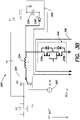
- FIGS. 3A and 3B are schematic diagrams illustrating the online mode of operation during positive and negative half cycles of the input AC voltage corresponding to the input AC power.
- the first converter switch 216 is operated to provide DC power to the DC bus 206 derived from the input AC power (provided by the input AC source 203).
- the first converter switch 216, the inductor 224, the second diode 228, and the first capacitor 232 are operated as a PFC boost converter to provide DC power to the first rail 206a of the DC bus 206.
- the first converter switch 216 is turned on and off to provide the PFC boost converter operation.
- the first converter switch 216 is turned on (i.e., closed)
- the first end of the inductor 224 is coupled to neutral.
- a conduction path 302 for the input AC power is provided through the first converter switch 216, energizing the inductor 224.
- the conduction path 302 may include at least one body diode of the switches 216a, 216b of the first converter switch 216.
- the inductor 224 is decoupled from neutral.
- a conduction path 304 for the input AC power is provided through the inductor 224 and the second diode 228 to charge the first capacitor 232 and provide DC power to the first rail 206a of the DC bus 206.
- the first converter switch 216 is operated in a similar manner to provide DC power to the DC bus 206 derived from the input AC power.
- the first converter switch 216, the inductor 224, the third diode 230, and the second capacitor 234 are operated as a PFC boost converter to provide DC power to the second rail 206b of the DC bus 206.
- the first converter switch 216 is turned on and off to provide the PFC boost converter operation.
- the first converter switch 216 is turned on (i.e., closed)
- the first end of the inductor 224 is coupled to neutral and a conduction path 306 for the input AC power is provided through the first converter switch 216, energizing the inductor 224.
- the conduction path 306 may include at least one body diode of the switches 216a, 216b of the first converter switch 216.
- the inductor 224 is decoupled from neutral.
- a conduction path 308 for the input AC power is provided through the inductor 224 and the third diode 230 to charge the second capacitor 234 and provide DC power to the second rail 206b of the DC bus 206.
- the second converter switch 218 remains turned off (i.e., opened) during the online mode of operation.
- the input selection circuit 220 is controlled to couple the second end of the inductor 224 to the backup power input 214 such that backup DC power from the backup power source 212 is provided to the converter 204.
- the converter 204 converts the backup DC power into DC power having the DC bus voltage level and provides the DC power having the DC bus voltage level to the DC bus 206.
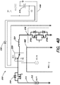
- FIGS. 4A and 4B are schematic diagrams illustrating the backup mode of operation during positive and negative half cycles of the output AC voltage corresponding to the output AC power provided by the inverter 208.
- the first converter switch 216 and the second converter switch 218 are operated to provide DC power to the DC bus 206 derived from the backup DC power (provided by the backup power source 212).
- the converter switches 216 and 218, the inductor 224, the second diode 228, and the first capacitor 232 are operated as a boost converter to provide DC power to the first rail 206a of the DC bus 206.
- the converter switches 216, 218 are transitioned between a first and a second switch state to provide the boost converter operation.
- the first converter switch 216 is turned on (i.e., closed) to couple the first end of the inductor 224 to neutral.
- the second converter switch 218 is turned on (i.e., closed) to couple the backup power input 214 to the input selection circuit 220.
- a conduction path 402 for the backup DC power is provided through the first and second converter switches 216, 218, energizing the inductor 224.
- the conduction path 402 may include at least one body diode of the switches 216a, 216b of the first converter switch 216.
- the first converter switch 216 is turned off (i.e., opened) to decouple the inductor 224 from neutral and the second converter switch 218 remains turned on (i.e., closed).
- a conduction path 404 for the backup DC power is provided through the second converter switch 218, the inductor 224, and the second diode 228 to charge the first capacitor 232 and provide DC power to the first rail 206a of the DC bus 206.
- the first and second converter switches 216, 218 are operated to provide DC power to the DC bus 206 derived from the backup DC power.
- the converter switches 216 and 218, the inductor 224, the first diode 226, and the second capacitor 234 are operated as a buck-boost converter to provide DC power to the second rail 206b of the DC bus 206.
- the converter switches 216, 218 are transitioned between a third and a fourth switch state to provide the buck-boost converter operation.
- the third switch state the first converter switch 216 is turned on (i.e., closed) to couple the first end of the inductor 224 to neutral.
- the second converter switch 218 is turned on (i.e., closed) to couple the backup power input 214 to the input selection circuit 220.
- a conduction path 406 for the backup DC power is provided through the first and second converter switches 216, 218, energizing the inductor 224.
- the conduction path 406 may include at least one body diode of the switches 216a, 216b of the first converter switch 216.
- the first converter switch 216 remains turned on (i.e., closed) and the second converter switch 218 is turned off (i.e., opened) to decouple the backup power input 214 from the input selection circuit 220.
- a conduction path 408 for the backup DC power is provided through the first diode 226, the inductor 224, and the first converter switch 216 to charge the second capacitor 234 and provide DC power to the second rail 206b of the DC bus 206.
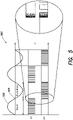
- FIG. 5 is a graph 500 illustrating control signals corresponding to operation of the UPS topology 200 in the backup mode of operation.
- a first control signal "G1" represents a gate drive signal provided to the gate of the first converter switch 216 (i.e., the gates of the switches 216a, 216b).
- a second control signal “G2" represents a gate drive signal provided to the gate of the second converter switch 218.
- the gate drive signals "G1" and “G2” are Pulse-Width Modulation (PWM) signals.
- the waveform 502 corresponds to the output of the inverter 208 (i.e., the output AC voltage) during the backup mode of operation.
- the UPS topology 200 is operated as a boost converter by transitioning the converter switches 216, 218 between the first and second switch states to provide DC power to the first rail 206a of the DC bus 206. As shown in the graph 500, the converter switches 216, 218 can be transitioned between the first and second switch states by modulating the first converter switch 216 via the gate drive signal "G1". Likewise, during the backup mode of operation and a negative half cycle of the output AC voltage 502, the UPS topology 200 is operated as a buck-boost converter by transitioning the converter switches 216, 218 between the third and fourth switch states to provide DC power to the second rail 206b of the DC bus 206. As shown in the graph 500, the converter switches 216, 218 can be transitioned between the third and fourth switch states by modulating the second converter switch 218 via the gate drive signal "G2".
- the first and second converter switches 216, 218 may be transitioned between the various switch states using an overlapping modulation scheme.
- the UPS topology is transitioned from boost converter operation (i.e., first/second switch states) to buck-boost converter operation (i.e., third/fourth switch states).
- boost converter operation i.e., first/second switch states
- buck-boost converter operation i.e., third/fourth switch states
- the gate drive signals "G1" and "G2" are configured such that the first and second converter switches 216, 218 are both on (i.e., closed) for an overlapping period of time.
- inductor 224 by preventing the inductor 224 from being disconnected during transitions, switching transients can be minimized and acceptable power quality can be maintained at the output 210 during the backup mode of operation. For example, maintaining a continuous inductor current may allow for high current spikes to be avoided, potentially preventing device and/or component failures.
- the topology includes a converter selectively coupled to an input configured to receive input AC power and a backup power input configured to receive backup DC power.
- the converter is configured to provide DC power to a DC bus of the UPS derived from either the input AC power or the backup DC power.
- the need for separate PFC and DC/DC converters can be eliminated.
- the UPS topology may have a reduced component count, increasing the power density of the UPS and reducing cost.
Landscapes
- Engineering & Computer Science (AREA)
- Power Engineering (AREA)
- Business, Economics & Management (AREA)
- Emergency Management (AREA)
- Rectifiers (AREA)
- Dc-Dc Converters (AREA)
Applications Claiming Priority (1)
| Application Number | Priority Date | Filing Date | Title |
|---|---|---|---|
| IN202011053522 | 2020-12-09 |
Publications (1)
| Publication Number | Publication Date |
|---|---|
| EP4012908A1 true EP4012908A1 (fr) | 2022-06-15 |
Family
ID=78676395
Family Applications (1)
| Application Number | Title | Priority Date | Filing Date |
|---|---|---|---|
| EP21208610.2A Pending EP4012908A1 (fr) | 2020-12-09 | 2021-11-16 | Convertisseur pfc et cc cc intégré pour un double bus cc pour une application asi en ligne |
Country Status (2)
| Country | Link |
|---|---|
| US (2) | US11705753B2 (fr) |
| EP (1) | EP4012908A1 (fr) |
Cited By (1)
| Publication number | Priority date | Publication date | Assignee | Title |
|---|---|---|---|---|
| EP4657710A1 (fr) * | 2024-05-31 | 2025-12-03 | Delta Electronics, Inc. | Dispositif, système et procédé d'alimentation électrique |
Families Citing this family (5)
| Publication number | Priority date | Publication date | Assignee | Title |
|---|---|---|---|---|
| KR102379157B1 (ko) * | 2020-11-04 | 2022-03-25 | 한국항공우주연구원 | 통합형 dc/dc 및 ac/dc 컨버터 시스템 |
| US11888340B2 (en) * | 2020-12-04 | 2024-01-30 | Schneider Electric It Corporation | Method to enhance the life of a lithium battery |
| CN115882578A (zh) * | 2021-09-29 | 2023-03-31 | 硕天科技股份有限公司 | 不断电系统及其电源转换电路 |
| FR3143228A1 (fr) | 2022-12-09 | 2024-06-14 | Commissariat A L'energie Atomique Et Aux Energies Alternatives | Circuit d’alimentation sans interruption |
| FR3148881B1 (fr) * | 2023-05-16 | 2025-11-28 | Commissariat Energie Atomique | Circuit d’alimentation sans interruption comprenant un convertisseur de tension abaisseur-elevateur |
Citations (1)
| Publication number | Priority date | Publication date | Assignee | Title |
|---|---|---|---|---|
| EP3661008A1 (fr) * | 2018-11-30 | 2020-06-03 | Schneider Electric IT Corporation | Batterie d'aviation avec extrémité avant pfc de commutateur en courant alternatif pour alimentation sans coupure (ups) |
Family Cites Families (5)
| Publication number | Priority date | Publication date | Assignee | Title |
|---|---|---|---|---|
| US6198176B1 (en) * | 1999-02-16 | 2001-03-06 | Statordyne Llc | UPS/CPS system |
| US9024476B2 (en) | 2011-07-28 | 2015-05-05 | Schneider Electric It Corporation | Single-battery power topologies for online UPS systems |
| US10183583B2 (en) * | 2016-08-03 | 2019-01-22 | Solarcity Corporation | Energy generation and storage system with electric vehicle charging capability |
| WO2018087876A1 (fr) * | 2016-11-11 | 2018-05-17 | 東芝三菱電機産業システム株式会社 | Appareil de système d'alimentation sans coupure |
| US10819140B1 (en) * | 2018-07-11 | 2020-10-27 | Maalouf Mark A | Systems and methods for remote monitoring and control of emergency electrical generating systems |
-
2021
- 2021-11-11 US US17/523,962 patent/US11705753B2/en active Active
- 2021-11-16 EP EP21208610.2A patent/EP4012908A1/fr active Pending
-
2023
- 2023-05-25 US US18/201,801 patent/US12003135B2/en active Active
Patent Citations (1)
| Publication number | Priority date | Publication date | Assignee | Title |
|---|---|---|---|---|
| EP3661008A1 (fr) * | 2018-11-30 | 2020-06-03 | Schneider Electric IT Corporation | Batterie d'aviation avec extrémité avant pfc de commutateur en courant alternatif pour alimentation sans coupure (ups) |
Cited By (1)
| Publication number | Priority date | Publication date | Assignee | Title |
|---|---|---|---|---|
| EP4657710A1 (fr) * | 2024-05-31 | 2025-12-03 | Delta Electronics, Inc. | Dispositif, système et procédé d'alimentation électrique |
Also Published As
| Publication number | Publication date |
|---|---|
| US20220181905A1 (en) | 2022-06-09 |
| US12003135B2 (en) | 2024-06-04 |
| US20240106263A1 (en) | 2024-03-28 |
| US11705753B2 (en) | 2023-07-18 |
Similar Documents
| Publication | Publication Date | Title |
|---|---|---|
| US11705753B2 (en) | Integrated PFC and DC DC converter for dual DC bus for online UPS application | |
| AU2012302148B2 (en) | Twin boost converter with integrated charger for ups | |
| US9024476B2 (en) | Single-battery power topologies for online UPS systems | |
| US11777338B2 (en) | AC switch PFC with integrated charger and DC-DC for online UPS systems | |
| AU2012286807B2 (en) | Dual boost converter for UPS system | |
| US9774263B1 (en) | Power converter with extended hold-up time | |
| US8878389B2 (en) | Method and apparatus for providing uninterruptible power | |
| US11728747B2 (en) | Soft switched voltage source inverter | |
| EP3588758A1 (fr) | Convertisseur cc-cc intégré | |
| US11387670B2 (en) | Double conversion on line ups with pass through neutral employing single DC bus | |
| US11990850B2 (en) | Soft switched voltage source inverter | |
| KR100490645B1 (ko) | 비절연형 무정전 전원공급 장치 | |
| EP3952081A1 (fr) | Appareil de conversion doté d'un circuit de commutation à trois niveaux et son procédé de fonctionnement | |
| CN121012179A (zh) | 不间断电源 |
Legal Events
| Date | Code | Title | Description |
|---|---|---|---|
| PUAI | Public reference made under article 153(3) epc to a published international application that has entered the european phase |
Free format text: ORIGINAL CODE: 0009012 |
|
| STAA | Information on the status of an ep patent application or granted ep patent |
Free format text: STATUS: THE APPLICATION HAS BEEN PUBLISHED |
|
| AK | Designated contracting states |
Kind code of ref document: A1 Designated state(s): AL AT BE BG CH CY CZ DE DK EE ES FI FR GB GR HR HU IE IS IT LI LT LU LV MC MK MT NL NO PL PT RO RS SE SI SK SM TR |
|
| STAA | Information on the status of an ep patent application or granted ep patent |
Free format text: STATUS: REQUEST FOR EXAMINATION WAS MADE |
|
| 17P | Request for examination filed |
Effective date: 20221213 |
|
| RBV | Designated contracting states (corrected) |
Designated state(s): AL AT BE BG CH CY CZ DE DK EE ES FI FR GB GR HR HU IE IS IT LI LT LU LV MC MK MT NL NO PL PT RO RS SE SI SK SM TR |
|
| STAA | Information on the status of an ep patent application or granted ep patent |
Free format text: STATUS: EXAMINATION IS IN PROGRESS |
|
| 17Q | First examination report despatched |
Effective date: 20230818 |