EP4012946A1 - Antennenpaneelauswahlverfahren, vorrichtung und speichermedium - Google Patents
Antennenpaneelauswahlverfahren, vorrichtung und speichermedium Download PDFInfo
- Publication number
- EP4012946A1 EP4012946A1 EP19940207.4A EP19940207A EP4012946A1 EP 4012946 A1 EP4012946 A1 EP 4012946A1 EP 19940207 A EP19940207 A EP 19940207A EP 4012946 A1 EP4012946 A1 EP 4012946A1
- Authority
- EP
- European Patent Office
- Prior art keywords
- antenna panel
- sending
- vehicle device
- identifier
- reference signal
- Prior art date
- Legal status (The legal status is an assumption and is not a legal conclusion. Google has not performed a legal analysis and makes no representation as to the accuracy of the status listed.)
- Pending
Links
Images




Classifications
-
- H—ELECTRICITY
- H04—ELECTRIC COMMUNICATION TECHNIQUE
- H04W—WIRELESS COMMUNICATION NETWORKS
- H04W4/00—Services specially adapted for wireless communication networks; Facilities therefor
- H04W4/30—Services specially adapted for particular environments, situations or purposes
- H04W4/40—Services specially adapted for particular environments, situations or purposes for vehicles, e.g. vehicle-to-pedestrians [V2P]
- H04W4/48—Services specially adapted for particular environments, situations or purposes for vehicles, e.g. vehicle-to-pedestrians [V2P] for in-vehicle communication
-
- H—ELECTRICITY
- H04—ELECTRIC COMMUNICATION TECHNIQUE
- H04B—TRANSMISSION
- H04B7/00—Radio transmission systems, i.e. using radiation field
- H04B7/02—Diversity systems; Multi-antenna system, i.e. transmission or reception using multiple antennas
- H04B7/04—Diversity systems; Multi-antenna system, i.e. transmission or reception using multiple antennas using two or more spaced independent antennas
- H04B7/06—Diversity systems; Multi-antenna system, i.e. transmission or reception using multiple antennas using two or more spaced independent antennas at the transmitting station
- H04B7/0602—Diversity systems; Multi-antenna system, i.e. transmission or reception using multiple antennas using two or more spaced independent antennas at the transmitting station using antenna switching
- H04B7/0608—Antenna selection according to transmission parameters
- H04B7/061—Antenna selection according to transmission parameters using feedback from receiving side
-
- H—ELECTRICITY
- H04—ELECTRIC COMMUNICATION TECHNIQUE
- H04B—TRANSMISSION
- H04B17/00—Monitoring; Testing
- H04B17/10—Monitoring; Testing of transmitters
- H04B17/11—Monitoring; Testing of transmitters for calibration
- H04B17/12—Monitoring; Testing of transmitters for calibration of transmit antennas, e.g. of the amplitude or phase
-
- H—ELECTRICITY
- H04—ELECTRIC COMMUNICATION TECHNIQUE
- H04B—TRANSMISSION
- H04B17/00—Monitoring; Testing
- H04B17/30—Monitoring; Testing of propagation channels
- H04B17/309—Measuring or estimating channel quality parameters
- H04B17/318—Received signal strength
- H04B17/328—Reference signal received power [RSRP]; Reference signal received quality [RSRQ]
-
- H—ELECTRICITY
- H04—ELECTRIC COMMUNICATION TECHNIQUE
- H04B—TRANSMISSION
- H04B17/00—Monitoring; Testing
- H04B17/30—Monitoring; Testing of propagation channels
- H04B17/382—Monitoring; Testing of propagation channels for resource allocation, admission control or handover
-
- H—ELECTRICITY
- H04—ELECTRIC COMMUNICATION TECHNIQUE
- H04B—TRANSMISSION
- H04B7/00—Radio transmission systems, i.e. using radiation field
- H04B7/02—Diversity systems; Multi-antenna system, i.e. transmission or reception using multiple antennas
- H04B7/04—Diversity systems; Multi-antenna system, i.e. transmission or reception using multiple antennas using two or more spaced independent antennas
- H04B7/06—Diversity systems; Multi-antenna system, i.e. transmission or reception using multiple antennas using two or more spaced independent antennas at the transmitting station
- H04B7/0613—Diversity systems; Multi-antenna system, i.e. transmission or reception using multiple antennas using two or more spaced independent antennas at the transmitting station using simultaneous transmission
- H04B7/0615—Diversity systems; Multi-antenna system, i.e. transmission or reception using multiple antennas using two or more spaced independent antennas at the transmitting station using simultaneous transmission of weighted versions of same signal
- H04B7/0619—Diversity systems; Multi-antenna system, i.e. transmission or reception using multiple antennas using two or more spaced independent antennas at the transmitting station using simultaneous transmission of weighted versions of same signal using feedback from receiving side
- H04B7/0621—Feedback content
- H04B7/0626—Channel coefficients, e.g. channel state information [CSI]
-
- H—ELECTRICITY
- H04—ELECTRIC COMMUNICATION TECHNIQUE
- H04B—TRANSMISSION
- H04B7/00—Radio transmission systems, i.e. using radiation field
- H04B7/02—Diversity systems; Multi-antenna system, i.e. transmission or reception using multiple antennas
- H04B7/04—Diversity systems; Multi-antenna system, i.e. transmission or reception using multiple antennas using two or more spaced independent antennas
- H04B7/06—Diversity systems; Multi-antenna system, i.e. transmission or reception using multiple antennas using two or more spaced independent antennas at the transmitting station
- H04B7/0613—Diversity systems; Multi-antenna system, i.e. transmission or reception using multiple antennas using two or more spaced independent antennas at the transmitting station using simultaneous transmission
- H04B7/0615—Diversity systems; Multi-antenna system, i.e. transmission or reception using multiple antennas using two or more spaced independent antennas at the transmitting station using simultaneous transmission of weighted versions of same signal
- H04B7/0619—Diversity systems; Multi-antenna system, i.e. transmission or reception using multiple antennas using two or more spaced independent antennas at the transmitting station using simultaneous transmission of weighted versions of same signal using feedback from receiving side
- H04B7/0621—Feedback content
- H04B7/0632—Channel quality parameters, e.g. channel quality indicator [CQI]
-
- H—ELECTRICITY
- H04—ELECTRIC COMMUNICATION TECHNIQUE
- H04L—TRANSMISSION OF DIGITAL INFORMATION, e.g. TELEGRAPHIC COMMUNICATION
- H04L5/00—Arrangements affording multiple use of the transmission path
- H04L5/003—Arrangements for allocating sub-channels of the transmission path
- H04L5/0048—Allocation of pilot signals, i.e. of signals known to the receiver
-
- H—ELECTRICITY
- H04—ELECTRIC COMMUNICATION TECHNIQUE
- H04L—TRANSMISSION OF DIGITAL INFORMATION, e.g. TELEGRAPHIC COMMUNICATION
- H04L5/00—Arrangements affording multiple use of the transmission path
- H04L5/003—Arrangements for allocating sub-channels of the transmission path
- H04L5/0053—Allocation of signalling, i.e. of overhead other than pilot signals
-
- H—ELECTRICITY
- H04—ELECTRIC COMMUNICATION TECHNIQUE
- H04W—WIRELESS COMMUNICATION NETWORKS
- H04W24/00—Supervisory, monitoring or testing arrangements
- H04W24/08—Testing, supervising or monitoring using real traffic
-
- H—ELECTRICITY
- H04—ELECTRIC COMMUNICATION TECHNIQUE
- H04W—WIRELESS COMMUNICATION NETWORKS
- H04W24/00—Supervisory, monitoring or testing arrangements
- H04W24/10—Scheduling measurement reports ; Arrangements for measurement reports
-
- H—ELECTRICITY
- H04—ELECTRIC COMMUNICATION TECHNIQUE
- H04W—WIRELESS COMMUNICATION NETWORKS
- H04W4/00—Services specially adapted for wireless communication networks; Facilities therefor
- H04W4/30—Services specially adapted for particular environments, situations or purposes
- H04W4/40—Services specially adapted for particular environments, situations or purposes for vehicles, e.g. vehicle-to-pedestrians [V2P]
-
- H—ELECTRICITY
- H04—ELECTRIC COMMUNICATION TECHNIQUE
- H04W—WIRELESS COMMUNICATION NETWORKS
- H04W4/00—Services specially adapted for wireless communication networks; Facilities therefor
- H04W4/30—Services specially adapted for particular environments, situations or purposes
- H04W4/40—Services specially adapted for particular environments, situations or purposes for vehicles, e.g. vehicle-to-pedestrians [V2P]
- H04W4/46—Services specially adapted for particular environments, situations or purposes for vehicles, e.g. vehicle-to-pedestrians [V2P] for vehicle-to-vehicle communication [V2V]
-
- H—ELECTRICITY
- H04—ELECTRIC COMMUNICATION TECHNIQUE
- H04B—TRANSMISSION
- H04B17/00—Monitoring; Testing
- H04B17/30—Monitoring; Testing of propagation channels
- H04B17/309—Measuring or estimating channel quality parameters
- H04B17/336—Signal-to-interference ratio [SIR] or carrier-to-interference ratio [CIR]
-
- H—ELECTRICITY
- H04—ELECTRIC COMMUNICATION TECHNIQUE
- H04L—TRANSMISSION OF DIGITAL INFORMATION, e.g. TELEGRAPHIC COMMUNICATION
- H04L5/00—Arrangements affording multiple use of the transmission path
- H04L5/003—Arrangements for allocating sub-channels of the transmission path
- H04L5/0048—Allocation of pilot signals, i.e. of signals known to the receiver
- H04L5/0051—Allocation of pilot signals, i.e. of signals known to the receiver of dedicated pilots, i.e. pilots destined for a single user or terminal
Definitions
- the present disclosure relates to a field of communication technologies, and particularly to a method and an apparatus for selecting an antenna panel, and a storage medium.
- V2X technology is a new generation of information and communication technology that connects the vehicle with everything, where V represents the vehicle and X represents any object that interacts with the vehicle. Vehicles that communicate in V2X technology or objects that interact with vehicles may be called vehicle devices.
- a vehicle terminal in order to improve coverage, a vehicle terminal is provided with a plurality of antenna panels.
- a panel with different directions can be set at different positions such as the left front, right front, left rear, and right rear of the vehicle.
- the sending vehicle device can use different panels for sending data to the receiving vehicle device according to different directions of the receiving vehicle device, thereby improving coverage.
- the sending vehicle device cannot determine whether the panel in the direction is a panel suitable for improving coverage. Therefore, when there are multiple panels in the sending vehicle device, how to determine a panel that is suitable for data transmission and reception with the receiving vehicle device and can improve coverage is a problem that needs to be solved.
- embodiments of the present disclosure provide a method and an apparatus for selecting an antenna panel, and a storage medium.
- a method for selecting an antenna panel is provided, which is applied to a sending vehicle device, and includes: sending a first control signaling, wherein the first control signaling includes a sending source identifier, and is configured to instruct a receiving vehicle device to measure antenna panels of the sending vehicle device identified by the sending source identifier; and receiving an antenna panel measurement result reported by the receiving vehicle device.
- the first control signaling further includes one or more combination of a destination identifier, a first antenna panel identifier, a first reference signal identifier, and a measurement result reporting configuration.
- the measurement result reporting configuration includes: a second reference signal identifier and a reference signal measurement value; or a second antenna panel identifier, a second reference signal identifier, and a reference signal measurement value.
- the measurement result reporting configuration further includes: a reference signal measurement threshold; and/or a maximum number of reference signal measurement values reported on each antenna panel.
- the measurement result reporting configuration includes: a second antenna panel identifier and an antenna panel measurement value; or a second antenna panel identifier, an antenna panel measurement value, and a reference signal measurement value; or a second antenna panel identifier, a second reference signal identifier, an antenna panel measurement value, and a reference signal measurement value.
- the measurement result reporting configuration further comprises at least one of following configuration information: a reference signal measurement threshold; a maximum number of reference signal measurement values reported on each antenna panel; a number of reference signal measurement values used for determining an antenna panel measurement value.
- the method further includes: sending a second control signaling, wherein the second control signaling comprises sending antenna panel indication information and data time-frequency resource information; and sending data using a selected antenna panel.
- sending the second control signaling includes: sending the second control signaling using one or more antenna panels.
- a method for selecting an antenna panel which is applied to a receiving vehicle device, and includes: detecting a first control signaling, wherein the first control signaling includes a sending source identifier, and is configured to instruct the receiving vehicle device to measure antenna panels of a sending vehicle device identified by the sending source identifier; and measure the antenna panels of the sending vehicle device identified by the sending source identifier, and reporting an antenna panel measurement result.
- the first control signaling further includes a destination identifier; before measuring antenna panels of the sending vehicle device identified by the sending source identifier, the method further includes: determining that the destination identifier exists in a stored list of existing destination identifiers.
- the first control signaling further includes a first reference signal identifier; measuring the antenna panels of the sending vehicle device identified by the sending source identifier includes: determining a time-frequency resource location corresponding a reference signal identified by the first reference signal identifier; measuring a measurement value of the reference signal on the antenna panel of the sending vehicle device identified by the sending source identifier at the time-frequency resource location.
- the first control signaling further includes a measurement result reporting configuration; reporting the antenna panel measurement result includes: reporting content that matches the measurement result reporting configuration according to the measurement result reporting configuration.
- the content that matches the measurement result reporting configuration includes: a second reference signal identifier and a reference signal measurement value; or a second antenna panel identifier, a second reference signal identifier, and a reference signal measurement value; or a second antenna panel identifier and an antenna panel measurement value; or a second reference signal identifier, an antenna panel measurement value, and a reference signal measurement value; or a second antenna panel identifier, a reference signal identifier, an antenna panel measurement value, and a reference signal measurement value.
- the method further includes: receiving a second control signaling, wherein the second control signaling includes sending antenna panel indication information and data time-frequency resource information; and receiving data on time-frequency resource indicated by the data time-frequency resource information by using a receiving antenna panel corresponding to a sending antenna panel indicated by the sending antenna panel indication information, wherein the receiving antenna panel corresponding to the sending antenna panel is an antenna panel determined when measuring the antenna panels of the sending vehicle device identified by the sending source identifier.
- an apparatus for selecting an antenna panel which is applied to a sending vehicle device, and includes: a sending unit, configured to send a first control signaling, wherein the first control signaling includes a sending source identifier, and is configured to instruct a receiving vehicle device to measure antenna panels of the sending vehicle device identified by the sending source identifier; and a receiving unit, configured to receive an antenna panel measurement result reported by the receiving vehicle device.
- the sending unit is further configured to: send a second control signaling, wherein the second control signaling comprises sending antenna panel indication information and data time-frequency resource information; and send data using a selected antenna panel.
- an apparatus for selecting an antenna panel which is applied to a receiving vehicle device, and includes: a detecting unit, configured to detect a first control signaling, wherein the first control signaling comprises a sending source identifier, and is configured to instruct the receiving vehicle device to measure antenna panels of a sending vehicle device identified by the sending source identifier; a measuring unit, configured to measure the antenna panels of the sending vehicle device identified by the sending source identifier; and a reporting unit, configured to report an antenna panel measurement result.
- the apparatus further includes a receiving unit, and the receiving unit is configured to:
- an apparatus for selecting an antenna panel including:
- an apparatus for selecting an antenna panel including:
- the technical solutions provided by embodiments of the present disclosure may include the following beneficial effects.
- the sending vehicle device sends the first control signaling for instructing the receiving vehicle device to measure the antenna panels of the sending vehicle device identified by the sending source identifier, in which the first control signaling includes the sending source identifier, and receives the antenna panel measurement result reported by the receiving vehicle device, such that the sending vehicle device can select an antenna panel suitable for the receiving vehicle device.
- the method for selecting an antenna panel provided by the embodiments of the present disclosure can be applied to a communication scenario of direct communication between two devices, such as a vehicle-to-other node (V2X) wireless communication scenario, and the like.
- V represents the vehicle device
- X represents any object that interacts with the vehicle device.
- X mainly includes vehicle devices, handheld devices, traffic roadside infrastructure and networks.
- the information modes of V2X interaction include: interaction of Vehicle to Vehicle (V2V), Vehicle to Infrastructure (V2I), Vehicle to Pedestrian (V2P), and Vehicle to Network (V2N).
- the communication scenario of direct communication between two devices may also be a Device to Device (D2D) communication scenario.
- D2D Device to Device
- the devices that perform direct communication in embodiments of the present disclosure may include various handheld devices, vehicle devices, wearable devices, computing devices, or other processing devices connected to wireless modems with wireless communication functions, and various forms of User Equipment (UE), mobile station (MS), terminal, terminal equipment and so on.
- UE User Equipment
- MS mobile station
- terminal equipment terminal equipment and so on.
- UE User Equipment
- embodiments of the present disclosure are described below by taking a scenario of direct communication between vehicle devices as an example, wherein the vehicle devices that perform direct communication include a sending vehicle device as a data transmitter and a receiving vehicle device as a data receiver.
- FIG. 1 is a schematic diagram of a scenario of direct communication between vehicle devices.
- the network device configures various transmission parameters for data transmission for the vehicle device 1.
- the vehicle device 1 acts as the sending vehicle device
- the vehicle device 2 and vehicle device 3 act as receiving vehicle devices
- the vehicle device 1 and the vehicle device 2 perform direct communication
- the vehicle device 1 and the vehicle device 3 perform direct communication.
- Direct communication can also be performed between the vehicle device 2 and the vehicle device 3.
- the link for communication between the network device and the vehicle device is an uplink and downlink, and the link between the vehicle device and the vehicle device is a sidelink.
- the vehicle device involved in the present disclosure includes one or more panels.
- LTE Long Term Evolution
- NR New Radio
- the vehicle device can be provided with multiple panels.
- a panel with different directions can be set at different positions such as the left front, right front, left rear, and right rear of the vehicle.
- the sending vehicle device cannot determine a panel that is suitable for data transmission with the receiving vehicle device and can improve coverage.
- the present disclosure provides a method for selecting an antenna panel.
- the sending vehicle device sends a control signaling, and the control signaling includes a sending source identifier.
- the control signaling is configured to instruct the receiving vehicle device to measure antenna panels of the sending vehicle device identified by the sending source identifier.
- the sending vehicle device receives an antenna panel measurement result reported by the receiving vehicle device, and selects the antenna panel suitable for sending data to the receiving vehicle device according to the antenna panel measurement result, to improve the coverage.
- the data sent by the sending vehicle device to the receiving vehicle device in the present disclosure includes one or more of data sent on a service channel of the sidelink, control signaling sent on the control channel, and synchronization signal blocks.
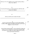
- FIG. 2 is a flowchart illustrating a method for selecting an antenna panel according to an example embodiment. As shown in FIG. 2 , the method for selecting an antenna panel is used in a sending vehicle device, and includes the following steps.
- step S 11 a control signaling is sent.
- the control signaling sent by the sending vehicle device includes a sending source identifier (source ID), and the sending source ID represents the identifier of the sending vehicle device and can identify the sending vehicle device.
- the control signaling including the sending source identifier is configured to instruct the receiving vehicle device to measure antenna panels of the sending vehicle device identified by the sending source identifier.
- control signaling including the sending source identifier and configured to instruct the receiving vehicle device to measure the antenna panels of the sending vehicle device identified by the sending source identifier is referred to as a first control signaling.
- the first control signaling further includes one or more combination of a destination identifier (destination ID), an antenna panel identifier used for antenna panel measurement, a reference signal identifier used for antenna panel measurement, and a measurement result reporting configuration.
- destination ID a destination identifier
- antenna panel identifier used for antenna panel measurement
- reference signal identifier used for antenna panel measurement
- the destination ID may represent the ID of the receiving vehicle device. If the sending vehicle device needs to send the first control signaling to all vehicle devices in a certain vehicle device group, the destination ID may represent the ID of the receiving vehicle device group. For the receiving vehicle device, multiple IDs will also be saved, such as its own vehicle device ID and one or more vehicle device group IDs. As long as the destination ID is found to be the same as one of the multiple IDs saved by itself, it means that the receiving vehicle device itself needs to perform according to the first control signaling.
- an antenna panel identifier is configured, and one or more reference signal identifiers to be measured are configured for the antenna panel identifier.
- the first control signaling includes the antenna panel identifier or reference signal identifier to be measured, and then according to the antenna panel identifier or reference signal identifier to be measured, the receiving vehicle device can measure the antenna panel corresponding to the vehicle device for the resource identified by the antenna panel identifier or the reference signal identifier.
- the antenna panel identifier may be a numerical value, such as #0, #1; or a reference signal group identifier. Each reference signal group corresponds to one antenna panel.
- the reference signal used for antenna panel measurement may be a synchronization signal block (SSB) of the sidelink.
- the SSB of the sidelink can be abbreviated as S-SSB.
- the identifier of the S-SSB may be a sidelink SSB resource index (S-SRI).
- the reference signal used for antenna panel measurement may also be a channel state information reference signal (CSI-RS) or a demodulation reference signal (DMRS) of the sidelink.
- CSI-RS of the sidelink can be abbreviated as S-CSI-RS.
- the DMRS of the sidelink can be abbreviated as S-DMRS.
- the identifier of the S-CSI-RS may be a sidelink CSI-RS resource index (S-CRI).
- the identifier of the S-DMRS may be a sidelink DMRS resource index (S-DRI).
- the sending vehicle device and the receiving vehicle device may pre-store a mapping relationship between the reference signal identifier and the resource of the reference signal, so as to subsequently determine the resource for antenna panel measurement through the reference signal identifier.
- the resource of the reference signal may be time-domain resource, frequency-domain resource, code-domain resource, beam directions, and the like.
- the mapping relationship between the reference signal identifier and the resource of the reference signal is stored in the form of a list, and the list can be broadcast by the sending vehicle device or the network device.
- the antenna panel identifier used for antenna panel measurement is referred to as the first antenna panel identifier, and the first antenna panel identifier may also be understood as the identifier of the antenna panel to be measured.
- the reference signal identifier used for antenna panel measurement is called the first reference signal identifier, and the first reference signal identifier may also be understood as the identifier of the reference signal to be measured.
- the measurement result reporting configuration in the present disclosure may be at the reference signal level or at the antenna panel level.
- the measurement result reporting configuration is at the reference signal level, it can be understood that the reported measurement result is reported using the reference signal as the object.
- reference signal identifiers and reference signal measurement values can be reported, and one reference signal identifier corresponds to one reference signal measurement value.
- the measurement result reporting configuration may include the reference signal identifier and the reference signal measurement value.
- the measurement result reporting configuration further includes the antenna panel identifier in addition to the reference signal identifier and the reference signal measurement value.
- the reference signal identifier included in the measurement result reporting configuration is referred to as the second reference signal identifier
- the antenna panel identifier included in the measurement result reporting configuration is referred to as the second antenna panel identifier.
- the measurement result reporting configuration includes the second reference signal identifier, which indicates that the reference signal identifier needs to be included in the measurement result reported by the receiving vehicle device.
- the measurement result reporting configuration includes the second antenna panel identifier, which indicates that the second antenna panel identifier needs to be included in the measurement result reported by the receiving vehicle device.
- the measurement result reporting configuration when the measurement result reporting configuration is at the reference signal level, includes, in addition to the second reference signal identifier, the reference signal measurement value, and the second antenna panel identifier, the reference signal measurement threshold, so that the receiving vehicle device reports the reference signal measurement value greater than the reference signal measurement threshold and the corresponding reference signal identifier.
- the measurement result reporting configuration when the measurement result reporting configuration is at the reference signal level, the measurement result reporting configuration further includes: a maximum number of reference signal measurement values reported on each antenna panel.
- the reference signal measurement value may be one or more combination of layer 1-Reference signal received power (L1-RSRP), layer 1-Reference Signal Received Quality (L1-RSRQ), layer 1-Signal to Interference plus Noise Ratio (L1-SINR), and layer 1-Received Signal Strength Indicator (L1-RSSI).
- L1-RSRP layer 1-Reference signal received power
- L1-RSRQ layer 1-Reference Signal Received Quality
- L1-SINR layer 1-Signal to Interference plus Noise Ratio
- L1-RSSI layer 1-Received Signal Strength Indicator
- the measurement result reporting configuration of the antenna panel level may include: the second antenna panel identifier and the antenna panel measurement value; or the second reference signal identifier, the antenna panel measurement value, and the reference signal measurement value; or the second antenna panel identifier, the second reference signal identifier, the antenna panel measurement value, and the reference signal measurement value.
- the measurement result reporting configuration at the antenna panel level further includes: a number N of reference signal measurement values used for determining the antenna panel measurement value.
- the antenna panel measurement value is an average value or a weighted average value of the measurement values corresponding to the N reference signals with the highest measurement values on the antenna panel.
- N is a positive integer, and N may be 1 or greater than 1.
- the antenna panel measurement value may be one or more combination of L1-RSRP, L1-SINR, L1-RSRQ, L1-RSSI.
- the measurement result reporting configuration at the antenna panel level further includes: a reference signal measurement threshold.
- the antenna panel measurement value is an average value or a weighted average value of at most N reference signal measurement values on the antenna panel whose measurement values are greater than the reference signal measurement threshold.
- the measurement result reporting configuration at the antenna panel level further includes: the maximum number of reference signal measurement values reported on each antenna panel.
- step S12 the antenna panel measurement result reported by the receiving vehicle device is received.
- the receiving vehicle device operates according to the content included in the first control signaling, for example, performs antenna panel measurement, and reports the antenna panel measurement result according to the content in the measurement result reporting configuration.
- the sending vehicle device sends the first control signaling to the receiving vehicle device, where the first control signaling includes the sending source identifier and is configured to instruct the receiving vehicle device to measure the antenna panels of the sending vehicle device identified by the sending source identifier.
- the receiving vehicle device measures the antenna panels of the sending vehicle device identified by the sending source identifier and reports the antenna panel measurement result.
- the sending vehicle device selects a most suitable antenna panel for the receiving vehicle device.
- the most suitable antenna panel may be understood as an antenna panel capable of improving coverage, for example, an antenna panel with the highest measurement value included in the antenna panel measurement result.
- the most suitable antenna panel may be an antenna panel with a smaller load on the antenna panel included in the antenna panel measurement result according to the number of receiving vehicle devices, transmission delay, etc.
- the sending vehicle device selects the antenna panel according to the antenna panel measurement result. After the sending vehicle device has selected an antenna panel for the receiving vehicle device, the antenna panel is the antenna panel of the sending vehicle device. The sending vehicle device can use the selected antenna panel to transmit data to the receiving vehicle device.
- FIG. 3 is a flowchart of a method for selecting an antenna panel according to an example embodiment.
- the method for selecting an antenna panel shown in FIG. 3 further includes the following steps on the basis of the method for selecting an antenna panel shown in FIG. 2 .
- step S13 an antenna panel is selected according to the antenna panel measurement result.
- step S14 data is transmitted using the selected antenna panel.
- the sending vehicle device uses the selected antenna panel to transmit data, and the sending vehicle device can also send the control signaling to indicate indication information of the selected antenna panel and time-frequency resource information for transmitting data, to the receiving vehicle device.
- control signaling including antenna panel indication information and data time-frequency resource information is referred to as the second control signaling.
- step S15 the second control signaling is sent.
- the second control signaling includes sending antenna panel indication information and data time-frequency resource information.
- the second control signaling is sent using one or more antenna panels.
- the antenna panel that sends the second control signaling and the antenna panel that sends data are the same or different antenna panels, or the antenna panel that sends the second control signaling includes but is not limited to the antenna panel that sends data.
- the sending antenna panel indication information is configured to indicate the sending antenna panel.
- the sending antenna panel indication information includes a sending antenna panel identifier, so as to indicate the sending antenna panel through the sending antenna panel identifier.
- the antenna panel indication information is used to indicate the antenna panel used for sending data to each receiving vehicle device. It can be understood that, in the case that the vehicle device moves slowly, the transmitting beam on the antenna panel for transmitting data can be further indicated.
- FIG. 4 is a flowchart of a method for selecting an antenna panel according to an example embodiment. The method for selecting an antenna panel shown in FIG. 4 is applied to the receiving vehicle device, including the following steps.
- step S21 the first control signaling is detected.
- the first control signaling includes the sending source identifier, and is configured to instruct the receiving vehicle device to measure antenna panels of the sending vehicle device identified by the sending source identifier.
- the receiving vehicle device can always detect the first control signaling on the time-frequency resource for sending the first control signaling.
- the time-frequency resource for sending the first control signaling may be broadcast by the sending vehicle device or the network device, or may be pre-configured.
- the receiving vehicle device After detecting the first control signaling, the receiving vehicle device performs the operation indicated by the first control signaling.
- the first control signaling includes the sending source identifier
- performing the operation indicated by the first control signaling may be: measuring antenna panels of the sending vehicle device identified by the sending source identifier.
- the first control signaling includes a destination identifier. Performing the operation indicated by the first control signaling may be: before measuring the antenna panels of the sending vehicle device identified by the sending source identifier, determining that the destination identifier included in the first control signaling exists in a stored list of existing destination identifiers.
- the destination identifier of the receiving vehicle device may be pre-configured.
- a destination identifier set or list of the receiving vehicle device is configured by a higher layer such as the application layer.
- the destination identifier set or list may include the identifier of the receiving vehicle device itself, or may include the destination identifier of one or more receiving vehicle device groups joined by the receiving vehicle device, in which each receiving vehicle device group corresponds to a destination identifier.
- the receiving vehicle device stores the pre-configured destination identifier list as the existing destination identification list.
- the receiving vehicle device determines to perform the operation indicated in the first control signaling.
- the first control signaling includes a first reference signal identifier, or the first control signaling includes a first reference signal identifier and a first antenna panel identifier.
- Performing the operation indicated by the first control signaling may be: determining a time-frequency resource location corresponding to the reference signal identified by the first reference signal identifier, and measuring the measurement value of the reference signal on the antenna panel of the vehicle-mounted device identified by the sending source identifier at the time-frequency resource location.
- step S22 antenna panels of the sending vehicle device identified by the sending source identifier are measured.
- the receiving vehicle device determines that the stored list of existing destination identifiers includes the destination identifier in the first control signaling, then according to the first reference signal identifier included in the first control signaling, or according to the first reference signal identifier and the first antenna panel identifier included in the first control signaling, the time-frequency resource location corresponding to the first reference signal is determined, and then the measurement value of each reference signal is measured at the time-frequency resource location, such as measuring a combination of one or more of L1-RSRP, L1-SINR, L1-RSRQ, and L1-RSSI.
- step S23 the antenna panel measurement result is reported.
- the first control signaling further includes a measurement result reporting configuration. Performing the operation indicated by the first control signaling may be: according to the measurement result reporting configuration, reporting content that matches the measurement result reporting configuration.
- the content matching the measurement result reporting configuration includes: a second reference signal identifier and a reference signal measurement value; or the second antenna panel identifier, the second reference signal identifier, and the reference signal measurement value; or the second antenna panel identifier and the antenna panel measurement value; or the second reference signal identifier, the antenna panel measurement value, and the reference signal measurement value; or the second antenna panel identifier, the second reference signal identifier, the antenna panel measurement value, and the reference signal measurement value.
- the reported antenna panel measurement result is the second reference signal identifier (or may also include the second antenna panel identifier) + the reference signal measurement value.
- M is a positive integer greater than or equal to 1.
- the sending vehicle device can also obtain the measurement value of each antenna panel by using one or more reference signal measurement values on each antenna panel, so as to select a suitable antenna panel for sending data to the receiving device.
- the beam direction corresponding to the suitable reference signal on the suitable antenna panel can also be further selected for sending data to the receiving device.
- the reported antenna panel measurement result is the second antenna panel identifier + the antenna panel measurement value.
- the antenna panel measurement value is the average value of the measurement values of N reference signals with the largest measurement values (or at most N reference signals whose measurement value is greater than the reference signal measurement threshold) on the antenna panel.
- the antenna panel measurement value is the L1-RSRP of the antenna panel obtained as the average of the N largest L1-RSRPs.
- the antenna panel measurement value is the L1-SINR of the antenna panel obtained as the average of the N largest L1-SINRs.
- the antenna panel measurement value is the L1-RSRQ of the antenna panel obtained as the average of the N largest L1-RSRQs.
- the antenna panel measurement value is the L1-RSSI of the antenna panel obtained as the average of the N largest L1-RSSIs.
- the sending vehicle device can select a suitable antenna panel for sending data to the receiving vehicle device according to the measurement value of each antenna panel.
- the reported antenna panel measurement result is the second antenna panel identifier + the antenna panel measurement value + the second reference signal identifier + the reference signal measurement value, so that in addition to selecting a suitable antenna panel for sending data to the receiving vehicle device, the sending vehicle device can further select a suitable beam direction on the suitable antenna panel for sending data to the receiving vehicle device.
- the antenna panel measurement result when reporting the antenna panel measurement result, it also carries the sending source identifier (the identifier of the receiving vehicle device) and the destination identifier (the identifier of the sending vehicle device).
- FIG. 5 is a flowchart illustrating a method for selecting an antenna panel according to an example embodiment.
- the method for selecting an antenna panel shown in FIG. 5 further includes the following steps on the basis of the method shown in FIG. 4 .
- step S24 the second control signaling is received.
- the second control signaling includes sending antenna panel indication information and data time-frequency resource information.
- the receiving vehicle device performs detection on the time-frequency resource for sending the second control signaling.
- the time-frequency resource information for subsequently receiving data and the like are determined according to the data time-frequency resource information included in the second control signaling.
- the antenna panel information of the subsequent data is determined according to the sending antenna panel indication information included in the second control signaling.
- the sending antenna panel used by the sending vehicle device is determined according to the sending antenna panel indication information
- the receiving antenna panel suitable for receiving the data sent by the sending antenna panel is determined according to the sending antenna panel.
- the receiving antenna panel suitable for receiving the data sent by the sending antenna panel may be the receiving antenna panel determined when measuring the sending antenna panel of the sending vehicle device identified by the sending source identifier involved in the above method embodiments, for example, may be the receiving antenna panel with the highest measurement value determined when measuring the sending antenna panel of the sending vehicle device identified by the sending source identifier.
- the sending vehicle device uses panel#0 to send reference signal #0, and when measuring the antenna panels of the sending vehicle device identified by the sending source identifier, the receiving vehicle device determines that the signal is strongest when the receiving vehicle device uses panel#1 to receive the reference signal sent by panel#0, then the corresponding receiving antenna panel of the receiving vehicle device is panel#1 when the sending antenna panel indication information indicates that the sending antenna panel of the sending vehicle device is panel#0.
- step S25 data is received on the time-frequency resource indicated by the data time-frequency resource information by using the receiving antenna panel corresponding to the sending antenna panel indicated by the sending antenna panel indication information.
- the receiving vehicle device uses the receiving antenna panel corresponding to the sending antenna panel indicated by the sending antenna panel indication information to receive the data sent by the sending vehicle device.
- the sending vehicle device uses panel#0 to send reference signal #0, and when the receiving vehicle device measures the antenna panels of the sending vehicle device identified by the sending source identifier, it is determined that the signal is the strongest when the receiving vehicle device uses panel#1 to receive the reference signal sent by panel#0, then the receiving vehicle device uses panel#1 to receive subsequent data on the time-frequency resource indicated by the data time-frequency resource information when the antenna panel information indicated by the sending vehicle device is panel#0.
- the sending antenna panel is indicated through the sending antenna panel indication information in the second control signaling.
- the receiving vehicle device determines the receiving antenna panel suitable for receiving the data sent by the sending antenna panel indicated by the sending antenna panel indication information according to the sending antenna panel indicated by the sending antenna panel indication information and the measurement result of the antenna panel measurement performed according to the first control signaling, to improve coverage.
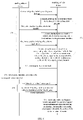
- FIG. 6 is a flowchart showing a method for selecting an antenna panel according to an example embodiment.
- the method for selecting an antenna panel shown in FIG. 6 is used in the interaction between the sending vehicle device and the receiving vehicle device. Referring to FIG. 6 , the method for selecting an antenna panel includes the following steps.
- step S31 the sending vehicle device sends the first control signaling.
- step S32 the receiving vehicle device detects the first control signaling, and performs the operation indicated by the first control signaling when the first control signaling is detected.
- the first control signaling sent by the sending vehicle device includes the sending source identifier, and is configured to instruct the receiving vehicle device to measure the antenna panels of the sending vehicle device identified by the sending source identifier.
- the operation performed by the receiving vehicle device according to the first control signaling may be: measuring the antenna panels of the sending vehicle device identified by the sending source identifier.
- the destination identifier is included in the first control signaling sent by the sending vehicle device.
- the operation performed by the receiving vehicle device according to the first control signaling may be: before measuring the antenna panels of the sending vehicle device identified by the sending source identifier, determining that the destination identifier included in the first control signaling exists in the stored list of existing destination identifiers.
- the first control signaling sent by the sending vehicle device includes the first reference signal identifier.
- the operation performed by the receiving vehicle device according to the first control signaling may be: determining a time-frequency resource location corresponding to the reference signal identified by the first reference signal identifier, and measuring measurement values of the reference signal on the antenna panel of the sending vehicle device identified by the sending source identifier at the time-frequency resource location.
- step S33 the antenna panel measurement result reported by the receiving vehicle is received.
- the receiving vehicle device receives the antenna panel measurement result.
- the first control signaling further includes a measurement result reporting configuration.
- the operation performed by the receiving vehicle device according to the first control signaling may be: according to the measurement result reporting configuration, reporting the content matching the measurement result reporting configuration.
- step S34 the sending vehicle device selects the antenna panel according to the antenna panel measurement result.
- step S35 the sending vehicle device sends data using the selected antenna panel.
- the sending vehicle device sends a second control signaling, where the second control signaling includes antenna panel indication information and data time-frequency resource information.
- step S36 the receiving vehicle device receives the second control signaling.
- the receiving vehicle device receives data on the time-frequency resource indicated by the data time-frequency resource information by using the receiving antenna panel corresponding to the sending antenna panel indicated by the sending vehicle device indication information.
- the sending vehicle device sends the first control signaling configured to instruct the receiving vehicle device to measure the antenna panels of the sending vehicle device identified by the sending source identifier, and the first control signaling includes the sending source identifier.
- the sending vehicle device receives the antenna panel measurement result reported by the receiving vehicle device, and according to the antenna panel measurement result, selects an antenna panel suitable for sending data to the receiving vehicle device, and uses the selected antenna panel to send data to the receiving vehicle device, to improve coverage.
- embodiments of the present disclosure further provide an apparatus for selecting an antenna panel.
- the apparatus for selecting an antenna panel provided by the embodiments of the present disclosure includes corresponding hardware structures and/or software modules for executing each function.
- the embodiments of the present disclosure can be implemented in hardware or a combination of hardware and computer software. Whether a function is performed by hardware or computer software driving hardware depends on the specific application and design constraints of the technical solution. Those skilled in the art may use different methods to implement the described functions for each specific application, but such implementation should not be considered beyond the scope of the technical solutions of the embodiments of the present disclosure.
- FIG. 7 is a block diagram of an apparatus for selecting an antenna panel provided according to an example embodiment of the present disclosure.
- the apparatus 100 for selecting an antenna panel is applied to a sending vehicle device, and includes a sending unit 101 and a receiving unit 102.
- the sending unit 101 is configured to send a first control signaling, wherein the first control signaling includes a sending source identifier, and is configured to instruct a receiving vehicle device to measure antenna panels of the sending vehicle device identified by the sending source identifier.
- the receiving unit 102 is configured to receive an antenna panel measurement result reported by the receiving vehicle device.
- the apparatus 100 for selecting an antenna panel further includes a processing unit 103, configured to select an antenna panel according to the antenna panel measurement result.
- the first control signaling further includes one or more combination of a destination identifier, a first antenna panel identifier, a first reference signal identifier, and a measurement result reporting configuration.
- the measurement result reporting configuration includes: a second reference signal identifier and a reference signal measurement value; or a second antenna panel identifier, a second reference signal identifier, and a reference signal measurement value.
- the measurement result reporting configuration further includes: a reference signal measurement threshold; and/or a maximum number of reference signal measurement values reported on each antenna panel.
- the measurement result reporting configuration includes: a second antenna panel identifier and an antenna panel measurement value; or a second antenna panel identifier, an antenna panel measurement value, and a reference signal measurement value; or a second antenna panel identifier, a second reference signal identifier, an antenna panel measurement value, and a reference signal measurement value.
- the measurement result reporting configuration further comprises at least one of following configuration information: a reference signal measurement threshold; a maximum number of reference signal measurement values reported on each antenna panel; a number of reference signal measurement values used for determining an antenna panel measurement value.
- the sending unit 101 is further configured to send a second control signaling, wherein the second control signaling includes sending antenna panel indication information and data time-frequency resource information.
- the sending unit 101 is further configured to send data using a selected antenna panel.
- the sending unit 101 is configured to send the second control signaling using one or more antenna panels.
- FIG. 8 is a block diagram of an apparatus for selecting an antenna panel provided according to an example embodiment of the present disclosure.
- the apparatus 200 for selecting an antenna panel is applied to a receiving vehicle device, and includes a detecting unit 201, a measuring unit 202 and a reporting unit 203.
- the detecting unit 201 is configured to detect a first control signaling, wherein the first control signaling includes a sending source identifier, and is configured to instruct the receiving vehicle device to measure antenna panels of a sending vehicle device identified by the sending source identifier.
- the measuring unit 202 is configured to measure the antenna panels of the sending vehicle device identified by the sending source identifier.
- the reporting unit 203 is configured to report an antenna panel measurement result.
- the first control signaling further includes a destination identifier.
- the detecting unit 201 is further configured to determine that the destination identifier exists in a stored list of existing destination identifiers before the measuring unit 202 measures antenna panels of the sending vehicle device identified by the sending source identifier.
- the first control signaling further includes a first reference signal identifier.
- the measuring unit 202 is configured to: determine a time-frequency resource location corresponding a reference signal identified by the first reference signal identifier; measure a measurement value of the reference signal on the antenna panel of the sending vehicle device identified by the sending source identifier at the time-frequency resource location.
- the first control signaling further includes a measurement result reporting configuration.
- the reporting unit 203 is configured to report content that matches the measurement result reporting configuration according to the measurement result reporting configuration.
- the content that matches the measurement result reporting configuration includes: a second reference signal identifier and a reference signal measurement value; or a second antenna panel identifier, a second reference signal identifier, and a reference signal measurement value; or a second antenna panel identifier and an antenna panel measurement value; or a second reference signal identifier, an antenna panel measurement value, and a reference signal measurement value; or a second antenna panel identifier, a reference signal identifier, an antenna panel measurement value, and a reference signal measurement value.
- the apparatus for selecting an antenna panel 200 further includes a receiving unit 204.
- the receiving unit 204 is configured to: receive a second control signaling, wherein the second control signaling includes sending antenna panel indication information and data time-frequency resource information; and receive data on time-frequency resource indicated by the data time-frequency resource information by using a receiving antenna panel corresponding to a sending antenna panel indicated by the sending antenna panel indication information, wherein the receiving antenna panel corresponding to the sending antenna panel is an antenna panel determined when measuring the antenna panels of the sending vehicle device identified by the sending source identifier.
- FIG. 9 is a block diagram illustrating an apparatus 300 for selecting an antenna panel according to an example embodiment.
- the apparatus 300 is applied to a sending vehicle device or a receiving vehicle device.
- the sending vehicle device or the receiving vehicle device may be a terminal.
- the apparatus 300 may be a mobile phone, a computer, a digital broadcasting terminal, a messaging device, a game console, a tablet device, a medical equipment, a fitness equipment, a personal digital assistant, etc.
- the apparatus 300 may include one or more components: a processing component 302, a memory 304, a power component 306, a multimedia component 308, an audio component 310, an input/output (I/O) interface 312, a sensor component 314, and a communication component 316.
- the processing component 302 generally controls the whole operation of the apparatus 300, such as the operations related to display, phone call, data communication, camera operation and recording operation.
- the processing component 302 may include one or more processors 320 to perform instructions, to complete all or part of blocks of the above method.
- the processing component 302 may include one or more modules for the convenience of interaction between the processing component 302 and other components.
- the processing component 302 may include a multimedia module for the convenience of interaction between the multimedia component 308 and the processing component 302.
- the memory 304 is configured to store all types of data to support the operation of the apparatus 300. Examples of the data include the instructions of any applications or methods operated on the apparatus 300, contact data, phone book data, messages, pictures, videos, etc.
- the memory 304 may be implemented by any type of temporary or non-temporary storage devices or their combination, such as a static random access memory (SRAM), an electrically erasable programmable read-only memory (EEPROM), an electrically programmable read-only memory (EPROM), a programmable read-only memory (PROM), a read-only memory (ROM), a magnetic memory, a flash memory, a magnetic disk or an optical disk.
- SRAM static random access memory
- EEPROM electrically erasable programmable read-only memory
- EPROM electrically programmable read-only memory
- PROM programmable read-only memory
- ROM read-only memory
- the power component 306 may provide power for all components of the apparatus 300.
- the power component 306 may include power supply management system, one or more power supplies, and other units related to generating, managing and distributing power for the apparatus 300.
- the multimedia component 308 includes an output interface screen provided between the apparatus 300 and the user.
- a screen may include a liquid crystal display (LCD) and a touch panel (TP).
- the screen may be implemented as a touch screen to receive an input signal from the user.
- the touch panel includes one or more touch sensors to sense touch, slide and gestures on the touch panel. The touch sensor may not only sense the boundary of the touch or slide action, but also detect the duration and pressure related to the touch or slide operation.
- the multimedia component 308 includes a front camera and/or a rear camera. When the apparatus 300 is in an operation mode, such as a shooting mode or a video mode, the front camera and/or the rear camera may receive external multimedia data.
- Each front camera and rear camera may be a fixed optical lens system or an optical lens system with a focal length and an optical zoom capacity.
- the audio component 310 is configured to output and/or input a signal.
- the audio component 310 includes a microphone (MIC).
- the microphone is configured to receive the external audio signals.
- the audio signal received may be further stored in the memory 304 or sent via the communication component 316.
- the audio component 310 further includes a speaker configured to output an audio signal.
- the I/O interface 312 provides an interface for the processing component 302 and the peripheral interface module, and the peripheral interface module may be a keyboard, a click wheel, a button, etc.
- the button may include but not limited to a home button, a volume button, a start button and a lock button.
- the sensor component 314 includes one or more sensors, configured to provide various aspects of status assessment for the apparatus 300.
- the sensor component 314 may detect the on/off state of the apparatus 300 and the relative positioning of the component.
- the component is a display and a keypad of the apparatus 300.
- the sensor component 314 may further detect the position change of the apparatus 300 or one component of the apparatus 300, the presence or absence of contact between the user and the apparatus 300, the orientation or acceleration/deceleration of the apparatus 300, and the temperature change of the apparatus 300.
- the sensor component 314 may include a proximity sensor configured to detect the existence of the objects nearby without any physical contact.
- the sensor component 314 may further include a light sensor such as CMOS or CCD image sensor, which is configured to use in imaging applications.
- the sensor component 314 may further include an acceleration transducer, a gyroscope sensor, a magnetic sensor, a pressure sensor or a temperature sensor.
- the communication component 316 is configured for the convenience of wire or wireless communication between the apparatus 300 and other devices.
- the apparatus 300 may access wireless networks based on a communication standard, such as WiFi, 2G or 3G, 4G LTE, 5G NR or their combination.
- the communication component 316 receives a broadcast signal or broadcast-related information from an external broadcast management system via a broadcast channel.
- the communication component 316 further includes a near field communication (NFC) module to facilitate short-range communication.
- NFC near field communication
- the NFC module may be achieved based on an RFID technology, an IrDA technology, a UWB technology, a BT technology and other technologies.
- the apparatus 300 may be implemented by one or more application specific integrated circuits(ASIC), digital signal processors (DSP), digital signal processing devices (DSPD), programmable logic devices (PLD), field programmable gate arrays (FPGA), controllers, microcontrollers, microprocessors or other electronics components, to perform the method as described in the above any embodiment.
- ASIC application specific integrated circuits
- DSP digital signal processors
- DSPD digital signal processing devices
- PLD programmable logic devices
- FPGA field programmable gate arrays
- controllers microcontrollers, microprocessors or other electronics components
- the apparatus 300 includes the processor 320 and the memory 304 configured to store instructions executable by the processor.
- the processor 320 is configured to implement the method described above.
- a non-transitory computer readable storage medium including instructions is further provided, such as a memory 304 including instructions, the instructions may be executed by the processor 320 of the apparatus 300 to complete the above method.
- the non-transitory computer readable storage medium may be a ROM, a random access memory (RAM), a CD-ROM, a magnetic tape, a floppy disk, an optical data storage device, etc.
- first, second, etc. are used to describe various information, but the information should not be limited to these terms. These terms are only used to distinguish the same type of information from one another, and do not imply a particular order or level of importance. In fact, the expressions “first”, “second” etc. are used completely interchangeably.
- the first information may also be referred to as the second information, and similarly, the second information may also be referred to as the first information, without departing from the scope of the present disclosure.
Landscapes
- Engineering & Computer Science (AREA)
- Signal Processing (AREA)
- Computer Networks & Wireless Communication (AREA)
- Quality & Reliability (AREA)
- Physics & Mathematics (AREA)
- Electromagnetism (AREA)
- Mobile Radio Communication Systems (AREA)
Applications Claiming Priority (1)
| Application Number | Priority Date | Filing Date | Title |
|---|---|---|---|
| PCT/CN2019/099291 WO2021022453A1 (zh) | 2019-08-05 | 2019-08-05 | 天线面板选择方法、装置及存储介质 |
Publications (2)
| Publication Number | Publication Date |
|---|---|
| EP4012946A1 true EP4012946A1 (de) | 2022-06-15 |
| EP4012946A4 EP4012946A4 (de) | 2023-04-26 |
Family
ID=68852413
Family Applications (1)
| Application Number | Title | Priority Date | Filing Date |
|---|---|---|---|
| EP19940207.4A Pending EP4012946A4 (de) | 2019-08-05 | 2019-08-05 | Antennenpaneelauswahlverfahren, vorrichtung und speichermedium |
Country Status (4)
| Country | Link |
|---|---|
| US (1) | US12407384B2 (de) |
| EP (1) | EP4012946A4 (de) |
| CN (2) | CN110603824B (de) |
| WO (1) | WO2021022453A1 (de) |
Families Citing this family (9)
| Publication number | Priority date | Publication date | Assignee | Title |
|---|---|---|---|---|
| CN112839304B (zh) * | 2019-11-22 | 2022-11-25 | 华为技术有限公司 | 通信方法及装置 |
| EP4102873A4 (de) * | 2020-02-04 | 2023-10-11 | Ntt Docomo, Inc. | Benutzerendgerät, drahtloskommunikationsverfahren und basisstation |
| CN113453189B (zh) * | 2020-03-25 | 2023-09-05 | 中国移动通信有限公司研究院 | 地铁天线系统、天线控制方法、网络侧设备及终端 |
| WO2021217457A1 (zh) * | 2020-04-28 | 2021-11-04 | 华为技术有限公司 | 一种定位信息的确定方法及通信装置 |
| US12356227B2 (en) * | 2020-07-09 | 2025-07-08 | Samsung Electronics Co., Ltd. | Uplink transmit beam selection based on downlink and uplink resource signal measurements |
| US12108269B2 (en) * | 2021-01-11 | 2024-10-01 | Qualcomm Incorporated | Distributed antenna panel measurement and reporting |
| EP4087150A1 (de) * | 2021-05-06 | 2022-11-09 | Nokia Technologies Oy | Verfahren zur strahlabtastung |
| EP4120580A1 (de) * | 2021-07-12 | 2023-01-18 | Nokia Technologies Oy | Bestimmung der von einem endgerät verwendeten antennengruppe im falle der höchstzulässigen exposition |
| CN115866756A (zh) * | 2021-09-23 | 2023-03-28 | 中国电信股份有限公司 | 终端及其天线面板选择方法和系统、基站和存储介质 |
Family Cites Families (28)
| Publication number | Priority date | Publication date | Assignee | Title |
|---|---|---|---|---|
| US20070111672A1 (en) * | 2005-11-14 | 2007-05-17 | Microsoft Corporation | Vehicle-to-vehicle communication |
| US9460388B2 (en) | 2013-05-30 | 2016-10-04 | Apple Inc. | Range class estimation for radio frequency devices |
| CN103458455A (zh) * | 2013-08-21 | 2013-12-18 | 中国联合网络通信集团有限公司 | 天线选择方法、基站和用户设备 |
| CN103491638B (zh) * | 2013-09-24 | 2017-07-28 | 华为技术有限公司 | 天线系统及处理方法 |
| DE102015202625A1 (de) * | 2014-02-14 | 2015-08-20 | Continental Automotive Gmbh | Fahrzeug-zu-X-Kommunikationssystem, Fahrzeug und Verfahren zum Senden von Fahrzeug-zu-X-Nachrichten |
| JP6274031B2 (ja) * | 2014-06-26 | 2018-02-07 | 株式会社オートネットワーク技術研究所 | 車両用通信システム、車載機、携帯機及びコンピュータプログラム |
| KR102288804B1 (ko) * | 2015-05-07 | 2021-08-11 | 삼성전자 주식회사 | 무선 통신 시스템에서 안테나를 선택하기 위한 방법 및 장치 |
| KR101728335B1 (ko) * | 2015-09-21 | 2017-05-02 | 현대자동차주식회사 | 안테나, 안테나 모듈 및 차량 |
| CN106559120B (zh) | 2015-09-25 | 2021-06-15 | 索尼公司 | 无线通信系统中的电子设备和无线通信方法 |
| DE102015012893A1 (de) * | 2015-10-06 | 2017-04-06 | Audi Ag | Kraftfahrzeug mit mehreren Antennen und wenigstens einer Kommunikationseinrichtung |
| WO2017067138A1 (en) * | 2015-10-21 | 2017-04-27 | Intel IP Corporation | Method, apparatus and system for reporting beam reference signal receiving power |
| JP2017184000A (ja) * | 2016-03-30 | 2017-10-05 | ソニー株式会社 | 通信装置、通信方法及びプログラム |
| US10405299B2 (en) * | 2016-09-14 | 2019-09-03 | Qualcomm Incorporated | Reference signal transmission based on received signal quality |
| CN108023841B (zh) * | 2016-11-04 | 2024-01-05 | 华为技术有限公司 | 准共址信息的发送接收方法、装置、网络设备及终端 |
| CN108347270A (zh) * | 2017-01-25 | 2018-07-31 | 华为技术有限公司 | 信道质量信息的上报方法、多用户调度方法及装置 |
| CN108631984B (zh) * | 2017-03-24 | 2022-11-15 | 中兴通讯股份有限公司 | 一种信息配置方法及装置 |
| WO2018232294A1 (en) * | 2017-06-16 | 2018-12-20 | Intel IP Corporation | Beam management with multi-transmission reception point multi-panel operation |
| EP3646636B1 (de) * | 2017-06-27 | 2024-11-06 | Telefonaktiebolaget LM Ericsson (publ) | Drahtloses kommunikationsgerät und verfahren zur netzwerkgesteuerten strahlbasierten übergabe in nr |
| CN109391993B (zh) * | 2017-08-10 | 2021-01-08 | 维沃移动通信有限公司 | 一种波束报告的发送方法及终端 |
| CN109391296A (zh) * | 2017-08-11 | 2019-02-26 | 索尼公司 | 用于无线通信的电子设备、方法和介质 |
| CN112929139B (zh) * | 2017-08-11 | 2022-05-20 | 中兴通讯股份有限公司 | 信息上报方法及装置、信息传输方法及装置 |
| CN109756977B (zh) * | 2017-11-03 | 2021-11-12 | 维沃移动通信有限公司 | 随机接入方法和用户终端 |
| CN110034803B (zh) * | 2018-01-12 | 2021-06-04 | 华为技术有限公司 | 无线通信系统中信道状态信息反馈方法和装置 |
| CN108964738B (zh) * | 2018-04-11 | 2021-09-28 | 莫志刚 | 一种用于轨道交通车地无线系统的车载天线系统 |
| US12074814B2 (en) * | 2018-09-27 | 2024-08-27 | Beijing Xiaomi Mobile Software Co., Ltd. | Measurement configuration method, apparatus, devices, system, and storage medium |
| CN111294891B (zh) * | 2018-12-07 | 2021-06-22 | 成都华为技术有限公司 | 一种天线面板及波束的管理方法和设备 |
| BR112021013120A2 (pt) | 2019-01-08 | 2021-09-14 | Beijing Xiaomi Mobile Software Co., Ltd. | Método e dispositivo de recebimento de dados de downlink, método e dispositivo de envio de dados de downlink e meio de armazenamento |
| US20230092424A1 (en) * | 2021-09-21 | 2023-03-23 | At&T Intellectual Property I, L.P. | Multifrequency operation for integrated access and backhaul |
-
2019
- 2019-08-05 CN CN201980001542.1A patent/CN110603824B/zh active Active
- 2019-08-05 EP EP19940207.4A patent/EP4012946A4/de active Pending
- 2019-08-05 US US17/631,465 patent/US12407384B2/en active Active
- 2019-08-05 CN CN202310324067.XA patent/CN116437324A/zh active Pending
- 2019-08-05 WO PCT/CN2019/099291 patent/WO2021022453A1/zh not_active Ceased
Also Published As
| Publication number | Publication date |
|---|---|
| US20220278719A1 (en) | 2022-09-01 |
| CN110603824A (zh) | 2019-12-20 |
| EP4012946A4 (de) | 2023-04-26 |
| CN110603824B (zh) | 2023-04-18 |
| US12407384B2 (en) | 2025-09-02 |
| WO2021022453A1 (zh) | 2021-02-11 |
| CN116437324A (zh) | 2023-07-14 |
Similar Documents
| Publication | Publication Date | Title |
|---|---|---|
| US12407384B2 (en) | Method and apparatus for selecting antenna panel | |
| US20230117493A1 (en) | Method for configuring resource for positioning-purpose reference signal and user equipment | |
| US11765023B2 (en) | Configuration method and apparatus for transmission configuration indication | |
| KR102542244B1 (ko) | 세컨더리 서빙 셀의 빔 실패의 보고 방법, 장치 및 저장 매체 | |
| US12501300B2 (en) | Method for reporting channel state information and communication device | |
| WO2021232429A1 (zh) | Srs资源配置方法、srs资源确定方法和装置 | |
| US12120064B2 (en) | Method and device for transmitting control information | |
| CN112438057A (zh) | 辅助资源集发送接收方法、装置及存储介质 | |
| EP3706093B1 (de) | Datenübertragungsverfahren, vorrichtung und unbemanntes luftfahrzeug | |
| CN110383749B (zh) | 控制信道发送、接收方法、装置及存储介质 | |
| US20250226963A1 (en) | Transmission direction determination method and apparatus, communication device, and storage medium | |
| US12532300B2 (en) | Auxiliary resource set determining method and apparatus, and storage medium | |
| CN113767683B (zh) | 波束管理方法及装置、通信设备及存储介质 | |
| CN113924810B (zh) | 数据传输处理方法、装置、通信设备及存储介质 | |
| US20240121061A1 (en) | Information transmission method, terminal device, base station, and storage medium | |
| WO2023050049A1 (zh) | 信息上报、波束切换方法及装置、存储介质 | |
| US20260031884A1 (en) | Beam reporting enhancement method and apparatus, and communication device and storage medium | |
| US20240357558A1 (en) | Communication method, user equipment, and network device | |
| RU2820333C1 (ru) | Способ и устройство для определения набора вспомогательных ресурсов, а также носитель данных | |
| US20250193866A1 (en) | Information transmission method and apparatus, and communication device and storage medium | |
| US12328606B2 (en) | Method and device for detecting control channel and method for transmitting information | |
| US12526773B2 (en) | Method and device for resource configuration | |
| US20240073881A1 (en) | Method and apparatus for indicating number of pucch transmissions, and repeat transmission method and apparatus | |
| CN119856409A (zh) | 信息处理方法及装置、通信设备及存储介质 | |
| WO2022226740A1 (zh) | 信息传输方法、装置、通信设备和存储介质 |
Legal Events
| Date | Code | Title | Description |
|---|---|---|---|
| STAA | Information on the status of an ep patent application or granted ep patent |
Free format text: STATUS: THE INTERNATIONAL PUBLICATION HAS BEEN MADE |
|
| PUAI | Public reference made under article 153(3) epc to a published international application that has entered the european phase |
Free format text: ORIGINAL CODE: 0009012 |
|
| STAA | Information on the status of an ep patent application or granted ep patent |
Free format text: STATUS: REQUEST FOR EXAMINATION WAS MADE |
|
| 17P | Request for examination filed |
Effective date: 20220302 |
|
| AK | Designated contracting states |
Kind code of ref document: A1 Designated state(s): AL AT BE BG CH CY CZ DE DK EE ES FI FR GB GR HR HU IE IS IT LI LT LU LV MC MK MT NL NO PL PT RO RS SE SI SK SM TR |
|
| DAV | Request for validation of the european patent (deleted) | ||
| DAX | Request for extension of the european patent (deleted) | ||
| A4 | Supplementary search report drawn up and despatched |
Effective date: 20230323 |
|
| RIC1 | Information provided on ipc code assigned before grant |
Ipc: H04L 5/00 20060101ALI20230317BHEP Ipc: H04W 4/48 20180101ALI20230317BHEP Ipc: H04B 17/318 20150101AFI20230317BHEP |
|
| STAA | Information on the status of an ep patent application or granted ep patent |
Free format text: STATUS: EXAMINATION IS IN PROGRESS |
|
| 17Q | First examination report despatched |
Effective date: 20240527 |