EP4012982A1 - Véhicule ferroviaire et réseau de communication associé - Google Patents
Véhicule ferroviaire et réseau de communication associé Download PDFInfo
- Publication number
- EP4012982A1 EP4012982A1 EP19939594.8A EP19939594A EP4012982A1 EP 4012982 A1 EP4012982 A1 EP 4012982A1 EP 19939594 A EP19939594 A EP 19939594A EP 4012982 A1 EP4012982 A1 EP 4012982A1
- Authority
- EP
- European Patent Office
- Prior art keywords
- communication
- area
- network
- carriage
- communication wire
- Prior art date
- Legal status (The legal status is an assumption and is not a legal conclusion. Google has not performed a legal analysis and makes no representation as to the accuracy of the status listed.)
- Granted
Links
Images

Classifications
-
- H—ELECTRICITY
- H04—ELECTRIC COMMUNICATION TECHNIQUE
- H04L—TRANSMISSION OF DIGITAL INFORMATION, e.g. TELEGRAPHIC COMMUNICATION
- H04L12/00—Data switching networks
- H04L12/28—Data switching networks characterised by path configuration, e.g. LAN [Local Area Networks] or WAN [Wide Area Networks]
- H04L12/42—Loop networks
-
- B—PERFORMING OPERATIONS; TRANSPORTING
- B61—RAILWAYS
- B61C—LOCOMOTIVES; MOTOR RAILCARS
- B61C17/00—Arrangement or disposition of parts; Details or accessories not otherwise provided for; Use of control gear and control systems
-
- B—PERFORMING OPERATIONS; TRANSPORTING
- B61—RAILWAYS
- B61L—GUIDING RAILWAY TRAFFIC; ENSURING THE SAFETY OF RAILWAY TRAFFIC
- B61L15/00—Indicators provided on the vehicle or train for signalling purposes
- B61L15/0018—Communication with or on the vehicle or train
- B61L15/0036—Conductor-based, e.g. using CAN-Bus, train-line or optical fibres
-
- B—PERFORMING OPERATIONS; TRANSPORTING
- B61—RAILWAYS
- B61L—GUIDING RAILWAY TRAFFIC; ENSURING THE SAFETY OF RAILWAY TRAFFIC
- B61L15/00—Indicators provided on the vehicle or train for signalling purposes
- B61L15/0063—Multiple on-board control systems, e.g. "2 out of 3"-systems
-
- B—PERFORMING OPERATIONS; TRANSPORTING
- B61—RAILWAYS
- B61L—GUIDING RAILWAY TRAFFIC; ENSURING THE SAFETY OF RAILWAY TRAFFIC
- B61L23/00—Control, warning or like safety means along the route or between vehicles or trains
-
- H—ELECTRICITY
- H04—ELECTRIC COMMUNICATION TECHNIQUE
- H04B—TRANSMISSION
- H04B3/00—Line transmission systems
- H04B3/54—Systems for transmission via power distribution lines
-
- H—ELECTRICITY
- H04—ELECTRIC COMMUNICATION TECHNIQUE
- H04B—TRANSMISSION
- H04B3/00—Line transmission systems
- H04B3/54—Systems for transmission via power distribution lines
- H04B3/544—Setting up communications; Call and signalling arrangements
-
- H—ELECTRICITY
- H04—ELECTRIC COMMUNICATION TECHNIQUE
- H04L—TRANSMISSION OF DIGITAL INFORMATION, e.g. TELEGRAPHIC COMMUNICATION
- H04L12/00—Data switching networks
- H04L12/28—Data switching networks characterised by path configuration, e.g. LAN [Local Area Networks] or WAN [Wide Area Networks]
- H04L12/42—Loop networks
- H04L12/437—Ring fault isolation or reconfiguration
Definitions
- the present invention relates to a network control technology for trains, in particular to a communication network for rail vehicles, and a rail vehicle.
- train network control technology can be used to ensure the effectiveness, safety and comfort of train control. It is indispensable for heavy freight trains, high-speed passenger trains, or urban rail transit vehicles.
- the data signal communication network adopted by the train on-board network control system has gradually transitioned from the traditional bus communication network in the past to the current Ethernet communication network.
- the real-time Ethernet communication network has various advantages including high bandwidth, strong real-time, and high redundancy.
- Ethernet As the most widely used communication network technology in the world, Ethernet has been well promoted and applied in many product technical fields such as civil and industrial products. With the widespread application of Ethernet technology, the product cost of the components required to establish a communication network is greatly reduced. The common standardized Ethernet communication protocol has also been widely and maturely used, and has been proved to be safe and reliable in actual use.
- the existing multi-group vehicle's Ethernet communication network often adopts a single fixed area location of the network equipment, and the ring-shaped network wire is directly connected across the carriages without separation or cross-connected across the carriages with separation.
- These two types of ring-shaped Ethernet communication networks inevitably have the disadvantages of high networking and wiring costs, or high costs for network protection design wiring.
- the present invention provides a communication network for rail vehicles, and a rail vehicle, which is used to reduce the networking cost of the Ethernet communication network of multi-group vehicles while to furthest improve the availability of communication networks.
- the rail vehicle includes a plurality of carriages
- the communication network includes:
- the first area of each carriage in every other carriage can be provided with the first network component, and the second area of each carriage in every other carriage can be provided with the first network component.
- the first network components can be sequentially arranged in each carriage in such a way that the first area and the second area are alternated.
- the first communication wire and the second communication wire may form the first communication loop through the first network components arranged in a first lead vehicle and a second lead vehicle.
- the above-mentioned communication network for rail vehicles may further include:
- the first area of each carriage in every other carriage may be provided with the first network component
- the second area of each carriage in every other carriage may be provided with the first network component
- the third area of each carriage in every other carriage may be provided with the second network component
- the fourth area of each carriage in every other carriage may be provided with the second network component.
- the first network components may be sequentially arranged in each carriage in such a way that the first area and the second area are alternate, and the second network components may be sequentially arranged in each carriage in such a way that the third area and the fourth area are alternate.
- the first area and the third area may be arranged in an upper area of each carriage and are isolated from each other, and the second area and the fourth area may be arranged in a lower area of each carriage and are isolated from each other, the first network component and the second network component in the same carriage may be arranged in the upper area and the lower area of the carriage respectively.
- the first communication wire and the second communication wire may form the first communication loop through the first network components arranged in a first lead vehicle and a second lead vehicle
- the third communication wire and the fourth communication wire may form the second communication loop through the second network components arranged in the first lead vehicle and the second lead vehicle.
- the area where the first network component is arranged and the area where the second network component is arranged in the first lead vehicle and the second lead vehicle may be isolated from each other.
- the areas where the first network component and the second network component are arranged in each carriage and the first lead vehicle and the second lead vehicle may include protective isolation area.
- the first network component and the second network component may include one or more of repeaters, switches, hubs, bridges and routers.
- the communication network may include Ethernet communication network.
- this article also provides a rail vehicle.
- the above-mentioned rail vehicle provided by the present invention includes a plurality of carriages, wherein the rail vehicle may include any one of the above-mentioned communication networks for rail vehicles.
- the above-mentioned rail vehicle provided by the present invention may include railway vehicles or urban rail transit vehicles.
- the terms “installation”, “connecting”, and “connected” should be understood broadly unless explicitly stated and defined otherwise.
- the terms “installation”, “connecting”, and “connected” may be either a fixed connection, a detachable connection, or an integral connection; the terms may be either a mechanical connection or an electrical connection; the terms also may be either a direct connection, an indirect connection through an intermediate medium, or an internal connection between two components.
- the specific meaning of the above terms in the present invention can be understood in a specific case by those skilled in the art.
- first”, “second”, “third”, etc. may be used to describe various components, regions, layers and/or portions to distinguish different components, regions, layers and/or portions, the order of these components, regions, layers and/or portions described above should not be limited by the terms. Therefore, a first component, region, layer and/or portion mentioned below may be also mentioned as a second component, region, layer and/or portion without departing from some embodiments of the present invention.
- the present invention provides an embodiment of a communication network for rail vehicles, and an embodiment of a rail vehicle, which is used to reduce the networking cost of the Ethernet communication network of multi-group vehicles, and to maximize improving the availability of the communication network at the same time.
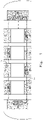
- FIG. 1 shows a schematic structural diagram of a communication network for rail vehicles according to an aspect of the present invention.
- rail vehicles include but are not limited to railway vehicles or urban rail transit vehicles, may include lead vehicles in two driving directions and a plurality of carriages.
- the communication network for rail vehicles may include a first communication wire 14 and a second communication wire 15.
- the above-mentioned first communication wire 14 may extend through the first area 11 of each carriage of the rail vehicle, so as to communicatively connect the lead vehicle areas 10 located in the two lead vehicles of the rail vehicle.
- the above-mentioned second communication wire 15 may extend the second area 12 of each carriage of the rail vehicle parallel to the first communication wire 14, so as to communicatively connect the lead vehicle areas 10 of the two lead vehicles of the rail vehicle and to form the first communication loop of the rail vehicle with the first communication wire 14 together.
- the first area 11 and the second area 12 may be arranged in protective isolation areas located in concealed positions in carriages of the rail vehicle (for example: at the top or bottom of the carriage), so as to avoid man-made or accidental interference factors.
- the above-mentioned protective isolation areas may refer to isolation areas enclosed in space, so as to prevent the first communication wire 14 and the second communication wire 15 from physical damage and interference such as man-made or accidental collisions and pulls.
- the above-mentioned protective isolation areas may also be preferably isolation areas with fire prevention and electromagnetic shielding functions, so as to avoid damage and interference from sudden situations such as fire and strong electromagnetic interference.
- the lead vehicle area 10 may be a space protection area provided on a side in the lead vehicle of the rail vehicle close to the carriage. By arranging the lead vehicle area 10 on the side close to the carriage in the lead vehicle, the length of the communication network can be effectively shortened, thereby reducing the wiring cost of the communication network and reducing signal interference in the communication network.
- the first area 11 and the second area 12 of each carriage of the rail vehicle can be respectively arranged at the top and bottom of the carriage, thereby realizing that the first communication wire 14 and the second communication wire 15 are isolated from each other.
- the two communication wires can be extended in the multiple carriages of the rail vehicle with isolation from each other, thereby avoiding power outages, technical faults or fire accidents to interfere with two communication wires at the same time, so as to improve the basic usability of the overall communication network.
- first communication wire 14 and the second communication wire 15 are respectively wired in the first area 11 and the second area 12 that are isolated from each other, and are communicatively connected in the lead vehicle area 10 of the two lead vehicles of the rail vehicle to form a ring-shaped communication network, when any communication wire is interfered or damaged, the two lead vehicles of the rail vehicle can still communicate data through the other communication wire.
- this separate networking method can further avoid interference of the two communication wires at the same time when strong electromagnetic interference or fire accidents occur at the connection of the carriages, so as to further improve the basic usability of the overall communication network.
- any one of the communication wires is interfered or damaged without affecting the basic usability of the overall communication network. Only when interferences or faults occur in the first area 11 and the second area 12 at the same time, the network communication will be affected, so that better anti-interference ability can be obtained.
- a first network component 13 for updating the communication data transmitted by the first communication wire 14 may be provided in the first area 11 of part of the carriages of the rail vehicle.
- a first network component 13 for updating the communication data transmitted by the second communication wire 15 may be provided in the second area 12 of part of the carriages of the rail vehicle.
- the first communication wire 14 and the second communication wire 15 may form a first communication loop through the first network components 13 arranged respectively in the first lead vehicle and the second lead vehicle.
- the above-mentioned communication network for rail vehicles provided in this embodiment may be constituted by the above-mentioned first communication loop, which includes but is not limited to an Ethernet communication network.
- the first network component 13 may be an Ethernet switch for the communication data transmitted by the first communication wire 14 and the second communication wire 15.
- the first network component 13 includes, but is not limited to, one or more of a repeater, a switch, a hub, a bridge, or a router, and can be used to transmit, enhance, and shunt the communication data in the above-mentioned Ethernet communication network.
- the above-mentioned Ethernet switches 13 may be sequentially arranged in each carriage of the rail vehicle in such a way that the first area 11 and the second area 12 are alternated. That is to say, in the first area 11 of each carriage of the rail vehicle, the Ethernet switches 13 of the first communication wire 14 can be arranged in every other carriage in the odd-numbered carriages. Correspondingly, in the second area 12 of each carriage of the rail vehicle described above, the Ethernet switches 13 of the second communication wire 15 can also be arranged in every other carriage in the even-numbered carriages.
- the Ethernet switches 13 of the first communication wire 14 and the second communication wire 15 are effectively prevented from being interfered at the same time, thereby further improving the basic usability of the overall communication network.
- those who skilled in the art can also according to the actual requirements of the transmitted communication data, in a manner of spaced apart any number of carriages, arrange the Ethernet switch 13 of the first communication wire 14 and the second communication wire 15 in different carriages, so as to prevent the first communication wire 14 and the second communication wire 15 from being interfered at the same time.
- the present invention further provides a preferred embodiment of a dual-loop communication network for rail vehicles.
- FIG. 2 shows a schematic structural diagram of a dual-loop communication network for rail vehicles according to an embodiment of the present invention.
- rail vehicles include but are not limited to railway vehicles or urban rail transit vehicles, and may include lead vehicles in two driving directions and a plurality of carriages.
- the dual-loop communication network for rail vehicles may not only include a first communication wire 26 and a second communication wire 27, but also may further include a third communication wire 28 and a fourth communication wire 29.
- the above-mentioned first communication wire 26 may extend through the first area 21 of each carriage of the rail vehicle, so as to communicatively connect the first lead vehicle areas 201 located in the two lead vehicles of the rail vehicle.
- the above-mentioned second communication wire 27 may extend through the second area 22 of each carriage of the rail vehicle parallel to the first communication wire 26, so as to communicatively connect the first lead vehicle areas 201 located in the two lead vehicles of the rail vehicle, and to form the first communication loop of the rail vehicle with the first communication wire 26 together.
- the above-mentioned third communication wire 28 may extend through the third area 23 of each carriage of the rail vehicle, so as to communicatively connect the second lead vehicle areas 202 located in the two lead vehicles of the rail vehicle.
- the above-mentioned fourth communication wire 29 may extend through the fourth area 24 of each carriage of the rail vehicle parallel to the third communication wire 28, so as to be communicatively connect the second lead vehicle areas 202 located in the two lead vehicles of the rail vehicle, and to form the second communication loop of the rail vehicle with the third communication wire 28 together.
- the first area 21 and the third area 23 may be protective isolation areas arranged at the top of the rail vehicle carriages
- the second area 22 and the fourth area 24 may be protective isolation areas arranged at the bottom of the rail vehicle carriages, so as to avoid man-made or accidental interference factors.
- the above-mentioned protective isolation areas may refer to isolation areas enclosed in space, so as to prevent the first communication wire 26, the second communication wire 27, the third communication wire 28, and the fourth communication wire 29 from physical damage and interference such as man-made or accidental collisions and pulls.
- the above-mentioned protective isolation areas may also be preferably isolation areas with fire prevention and electromagnetic shielding functions, so as to avoid damage and interference from sudden situations such as fire and strong electromagnetic interference.
- the above-mentioned top and bottom of the carriages are only a relative conception.
- the above-mentioned top of the carriages may further include the upper area of each carriage of the rail vehicle.
- the above-mentioned bottom of the carriages may further include the lower area of each carriage of the rail vehicle.
- the first lead vehicle area 201 and the second lead vehicle area 202 may be both a space protection area provided on a side in the lead vehicle of the rail vehicle close to the carriage.
- the length of the communication network can be effectively shortened, thereby reducing the wiring cost of the communication network and reducing signal interference in the communication network.
- the four communication wires can be extended in the multiple carriages of the rail vehicle with isolation from each other, thereby avoiding power outages, technical faults or fire accidents to interfere with four communication wires at the same time, so as to improve the basic usability of the overall communication network.
- those skilled in the art can also reverse the positions of the first area 21 and the second area 22, or the third area 23 and the fourth area 24 on basis of the conception of the present invention, or simply increase or decrease the number of space protection areas to obtain the same technical effect as the above embodiments.
- first communication wire 26 and the second communication wire 27 are respectively wired in the first area 21 and the second area 22 that are isolated from each other, and are communicatively connected in the first lead vehicle areas 201 of the two lead vehicles of the rail vehicle to form a first communication loop, when any communication wire of the first communication wire 26 and the second communication wire 27 is interfered or damaged, the two lead vehicles of the rail vehicle can still communicate data through the other communication wire of the first communication loop.
- the third communication wire 28 and the fourth communication wire 29 are respectively wired in the third area 22 and the fourth area 24 that are isolated from each other, and are communicatively connected in the second lead vehicle areas 202 of the two lead vehicles of the rail vehicle to form a second communication loop, when any communication wire of the third communication wire 28 and the fourth communication wire 29 is interfered or damaged, the two lead vehicles of the rail vehicle can still communicate data through the other communication wire of the second communication loop.
- the first communication wire 26, the second communication wire 27, the third communication wire 28, and the fourth communication wire 29 can be separately arranged at the top and bottom of the carriage.
- This separate networking method can further avoid interference of the four communication wires at the same time when strong electromagnetic interference or fire accidents occur at the connection of the carriages, so as to further improve the basic usability of the overall communication network.
- a first network component 251 for updating the communication data transmitted by the first communication wire 26 may be provided in the first area 21 of part of the carriages of the rail vehicle.
- a first network component 251 for updating the communication data transmitted by the second communication wire 27 may be provided in the second area 22 of part of the carriages of the rail vehicle.
- the first communication wire 26 and the second communication wire 27 may form a first communication loop through the first network components 251 arranged respectively in the first lead vehicle and the second lead vehicle.
- a second network component 252 for updating the communication data transmitted by the third communication wire 28 may be provided in the third area 23 of part of the carriages of the rail vehicle.
- a second network component 252 for updating the communication data transmitted by the fourth communication wire 29 may be provided in the fourth area 24 of part of the carriages of the rail vehicle.
- the third communication wire 28 and the fourth communication wire 29 may form a second communication loop through the second network components 252 arranged respectively in the first lead vehicle and the second lead vehicle.
- the above-mentioned dual-loop communication network for rail vehicles provided in this embodiment may be constituted of the above-mentioned first communication loop and the above-mentioned second communication loop.
- the dual-loop communication network for rail vehicles includes but is not limited to an Ethernet communication network.
- the first network component 251 may be an Ethernet switch for the communication data transmitted by the first communication wire 26 and the second communication wire 27, and the second network component 252 may be an Ethernet network switch for the communication data transmitted by the third communication wire 28 and the fourth communication wire 29.
- the first network component 251 and the second network component 252 include, but are not limited to, one or more of repeaters, switches, hubs, bridges, or routers, and can be used to transmit, enhance, and shunt the communication data in the above-mentioned Ethernet communication network.
- the above-mentioned first network component 251 may be sequentially arranged in each carriage of the rail vehicle in such a way that the first area 21 and the second area 22 are alternated. That is to say, in the first area 21 of each carriage of the rail vehicle, the first network components 251 of the first communication wire 26 can be arranged in every other carriage in the odd-numbered carriages.
- the first network components 251 of the second communication wire 27 can also be arranged in every other carriage in the even-numbered carriages.
- the above-mentioned second network components 252 may be sequentially arranged in each carriage of the rail vehicle in such a way that the third area 23 and the fourth area 24 are alternated. That is to say, in the third area 23 of each carriage of the rail vehicle, the second network components 252 of the third communication wire 28 can be arranged in every other carriage in the even-numbered carriages.
- the second network components 252 of the fourth communication wire 29 can also be arranged in every other carriage in the odd-numbered carriages.
- first network components 251 and the second network components 252 are arranged at intervals in the first area 21, the second area 22, the third area 23 and the fourth area of different carriages, when accidents such as power outages, fires, etc. occur in any carriage of the rail vehicle, the first communication loop and the second communication loop are effectively prevented from being interfered at the same time, thereby further improving the basic usability of the overall communication network.
- those who skilled in the art may also arrange the first network components 251 of the first communication loop and the second network components 252 of the second communication loop in different carriages in manner of spaced apart by any number of carriages, according to the actual requirements for the transmitted communication data, so as to prevent the first communication loop and the second communication loop from being interfered at the same time.
- the first network components 251 of the first communication loop and the second network components 252 of the second communication loop may be arranged in the upper area and the lower area of the carriages, respectively, so as to realize the isolation of the first network component 251 and the second network component 252 from each other, so as to prevent the first communication loop and the second communication loop from being damaged and interfered at the same time.
- first area 21 and the third area 23 arranged at the top of the rail vehicle carriage may preferably be isolated from each other.
- the second area 22 and the fourth area 24 arranged at the bottom of the rail vehicle carriage may preferably be isolated from each other.
- the first lead vehicle area 201 and the second lead vehicle area 202 arranged in the two lead vehicles of the rail vehicle may also be preferably isolated from each other.
- the above-mentioned isolation includes, but is not limited to, spatial isolation, fire isolation, waterproof isolation, and electromagnetic shielding isolation.
- the first communication wire 26 and the third communication wire 28 in the same carriage can be further isolated from each other, and the second communication wire 27 and the fourth communication wire 29 can be isolated from each other, thereby realizing the effect of isolating the first communication loop and the second communication loop, so as to prevent the first communication loop and the second communication loop from being interfered or damaged at the same time, so as to further improve the basic usability of the overall communication network.
- the present disclosure also provides an embodiment of a rail vehicle.
- the above-mentioned rail vehicles provided in this embodiment include but are not limited to railway vehicles or urban rail transit vehicles, which may include lead vehicles in two driving directions and a plurality of carriages, as well as the communication network for rail vehicles provided by any one of the above-mentioned embodiments, so as to reduce the networking cost of the Ethernet communication network of multi-group vehicles, and to maximize the availability of the communication network at the same time.
Landscapes
- Engineering & Computer Science (AREA)
- Mechanical Engineering (AREA)
- Computer Networks & Wireless Communication (AREA)
- Signal Processing (AREA)
- Automation & Control Theory (AREA)
- Transportation (AREA)
- Power Engineering (AREA)
- Train Traffic Observation, Control, And Security (AREA)
- Electric Propulsion And Braking For Vehicles (AREA)
- Small-Scale Networks (AREA)
Applications Claiming Priority (2)
| Application Number | Priority Date | Filing Date | Title |
|---|---|---|---|
| CN201910694986.XA CN112298222B (zh) | 2019-07-30 | 2019-07-30 | 一种轨道车辆及其通信网络 |
| PCT/CN2019/108370 WO2021017139A1 (fr) | 2019-07-30 | 2019-09-27 | Véhicule ferroviaire et réseau de communication associé |
Publications (4)
| Publication Number | Publication Date |
|---|---|
| EP4012982A1 true EP4012982A1 (fr) | 2022-06-15 |
| EP4012982A4 EP4012982A4 (fr) | 2023-08-30 |
| EP4012982C0 EP4012982C0 (fr) | 2025-08-13 |
| EP4012982B1 EP4012982B1 (fr) | 2025-08-13 |
Family
ID=74229626
Family Applications (1)
| Application Number | Title | Priority Date | Filing Date |
|---|---|---|---|
| EP19939594.8A Active EP4012982B1 (fr) | 2019-07-30 | 2019-09-27 | Véhicule ferroviaire et son réseau de communication |
Country Status (3)
| Country | Link |
|---|---|
| EP (1) | EP4012982B1 (fr) |
| CN (1) | CN112298222B (fr) |
| WO (1) | WO2021017139A1 (fr) |
Families Citing this family (2)
| Publication number | Priority date | Publication date | Assignee | Title |
|---|---|---|---|---|
| CN115396466B (zh) * | 2022-07-27 | 2024-06-18 | 交控科技股份有限公司 | 一种车厢底盘分离的轨道交通车地通信组网系统 |
| CN115412363B (zh) * | 2022-09-13 | 2024-06-28 | 杭州迪普科技股份有限公司 | 异常流量日志处理方法和装置 |
Family Cites Families (16)
| Publication number | Priority date | Publication date | Assignee | Title |
|---|---|---|---|---|
| JP3808824B2 (ja) * | 2002-11-20 | 2006-08-16 | 株式会社日立製作所 | 情報伝送システム及び情報伝送方法 |
| EP1645483A1 (fr) * | 2004-10-08 | 2006-04-12 | Recherche et Développement, Ingénierie s.a.r.l. | Système d'annonce automatique de trains |
| JP4987665B2 (ja) * | 2007-10-31 | 2012-07-25 | 株式会社東芝 | 鉄道車両用伝送システムおよび鉄道車両 |
| DE102010010074A1 (de) * | 2010-02-25 | 2011-08-25 | Siemens Aktiengesellschaft, 80333 | Spurgebundenes Fahrzeug |
| CN101941451B (zh) * | 2010-08-31 | 2012-12-05 | 北京交通大学 | 点式列车控制系统 |
| RU2457130C1 (ru) * | 2011-02-08 | 2012-07-27 | Открытое Акционерное Общество "Российские Железные Дороги" | Путевое передающее устройство управления поездом |
| DE102011117589A1 (de) * | 2011-11-03 | 2013-05-08 | Knorr-Bremse Systeme für Schienenfahrzeuge GmbH | Einheit mit Schaltfunktion für Ethernet |
| CN102523143B (zh) * | 2011-12-26 | 2014-10-08 | 易程(苏州)智能系统有限公司 | 一种高铁影音系统 |
| JP5634421B2 (ja) * | 2012-02-27 | 2014-12-03 | 三菱電機株式会社 | 車両制御情報管理システム |
| JP5490329B2 (ja) * | 2012-04-02 | 2014-05-14 | 三菱電機株式会社 | 列車用通信システム |
| CN104579606B (zh) * | 2014-09-19 | 2018-04-06 | 长春工业大学 | 多功能车辆总线mvb网络系统冗余设计方法 |
| CN104618202B (zh) * | 2015-01-05 | 2019-06-28 | 南车株洲电力机车研究所有限公司 | 一种城轨列车环形通信网络 |
| JP6353377B2 (ja) * | 2015-01-30 | 2018-07-04 | 川崎重工業株式会社 | 鉄道車両のネットワークシステム |
| CN105791071B (zh) * | 2016-02-23 | 2017-06-16 | 中车青岛四方车辆研究所有限公司 | 一种列车控制、服务共网的宽带通信网络架构及通信方法 |
| CN107181615A (zh) * | 2017-05-19 | 2017-09-19 | 中南大学 | 一种对crh2列车通信网络仿真的方法及装置 |
| CN207251675U (zh) * | 2017-09-12 | 2018-04-17 | 中车青岛四方机车车辆股份有限公司 | 一种列车受电弓视频监控系统及列车 |
-
2019
- 2019-07-30 CN CN201910694986.XA patent/CN112298222B/zh active Active
- 2019-09-27 WO PCT/CN2019/108370 patent/WO2021017139A1/fr not_active Ceased
- 2019-09-27 EP EP19939594.8A patent/EP4012982B1/fr active Active
Also Published As
| Publication number | Publication date |
|---|---|
| CN112298222B (zh) | 2022-12-09 |
| EP4012982A4 (fr) | 2023-08-30 |
| WO2021017139A1 (fr) | 2021-02-04 |
| EP4012982C0 (fr) | 2025-08-13 |
| CN112298222A (zh) | 2021-02-02 |
| EP4012982B1 (fr) | 2025-08-13 |
Similar Documents
| Publication | Publication Date | Title |
|---|---|---|
| KR101106380B1 (ko) | 고가용성 네트워크 시스템 | |
| JP2023162170A (ja) | 車両用回路体 | |
| RU2523869C2 (ru) | Коммуникационная сеть для связанного с колеей транспортного средства | |
| EP2705994B1 (fr) | Agencement de commande pour véhicule ferroviaire | |
| EP4012982B1 (fr) | Véhicule ferroviaire et son réseau de communication | |
| CN108819984B (zh) | 一种无人驾驶地铁列车的乘客报警输出控制电路 | |
| CN102275598A (zh) | 支持c3系统的计算机联锁系统及联锁控制方法 | |
| US20140312698A1 (en) | Unit having a switching function for ethernet | |
| CN102991536B (zh) | 时速250km/h动车组列车网络控制系统 | |
| JP2011166961A (ja) | 交流電気車 | |
| WO2013065079A1 (fr) | Système d'arrêt de freinage d'urgence par récupération | |
| CN107364468A (zh) | 远程隔离电路、无人驾驶列车的制动故障隔离系统及方法 | |
| CN205558404U (zh) | 充电型垂直循环式立体车库 | |
| CN208119176U (zh) | 一种用于铁路站间的闭塞信息传输系统 | |
| CN107959586A (zh) | 一种基于云平台的船端集成导航系统网络架构 | |
| CN207292035U (zh) | 远程隔离电路和用于无人驾驶列车的制动故障隔离系统 | |
| CN110979015A (zh) | 一种轨道车辆 | |
| CN211166464U (zh) | 一种轨道车辆 | |
| CN115548805B (zh) | 一种地铁列车 | |
| CN106740997A (zh) | 一种重联机车信息同步系统与方法 | |
| CN201816596U (zh) | 一种加装有无线重联设备的电力机车 | |
| CN116389531A (zh) | 一种基于以太网深度融合的列车网络架构 | |
| CN116424392A (zh) | 一种轨道车司机作业车载安全管理系统 | |
| CN103264705B (zh) | 基于pac控制器的can总线机车重联系统及实现方法 | |
| CN214728852U (zh) | 一种应用在随动式轨道上的通信装置 |
Legal Events
| Date | Code | Title | Description |
|---|---|---|---|
| STAA | Information on the status of an ep patent application or granted ep patent |
Free format text: STATUS: THE INTERNATIONAL PUBLICATION HAS BEEN MADE |
|
| PUAI | Public reference made under article 153(3) epc to a published international application that has entered the european phase |
Free format text: ORIGINAL CODE: 0009012 |
|
| STAA | Information on the status of an ep patent application or granted ep patent |
Free format text: STATUS: REQUEST FOR EXAMINATION WAS MADE |
|
| 17P | Request for examination filed |
Effective date: 20220224 |
|
| AK | Designated contracting states |
Kind code of ref document: A1 Designated state(s): AL AT BE BG CH CY CZ DE DK EE ES FI FR GB GR HR HU IE IS IT LI LT LU LV MC MK MT NL NO PL PT RO RS SE SI SK SM TR |
|
| DAV | Request for validation of the european patent (deleted) | ||
| DAX | Request for extension of the european patent (deleted) | ||
| REG | Reference to a national code |
Ref country code: DE Ref legal event code: R079 Free format text: PREVIOUS MAIN CLASS: H04L0012400000 Ipc: H04L0012420000 Ref document number: 602019074267 Country of ref document: DE |
|
| A4 | Supplementary search report drawn up and despatched |
Effective date: 20230727 |
|
| RIC1 | Information provided on ipc code assigned before grant |
Ipc: B61C 17/00 20060101ALI20230721BHEP Ipc: H04L 12/437 20060101ALI20230721BHEP Ipc: B61L 15/00 20060101ALI20230721BHEP Ipc: H04L 12/42 20060101AFI20230721BHEP |
|
| GRAP | Despatch of communication of intention to grant a patent |
Free format text: ORIGINAL CODE: EPIDOSNIGR1 |
|
| STAA | Information on the status of an ep patent application or granted ep patent |
Free format text: STATUS: GRANT OF PATENT IS INTENDED |
|
| INTG | Intention to grant announced |
Effective date: 20250306 |
|
| GRAS | Grant fee paid |
Free format text: ORIGINAL CODE: EPIDOSNIGR3 |
|
| GRAA | (expected) grant |
Free format text: ORIGINAL CODE: 0009210 |
|
| STAA | Information on the status of an ep patent application or granted ep patent |
Free format text: STATUS: THE PATENT HAS BEEN GRANTED |
|
| AK | Designated contracting states |
Kind code of ref document: B1 Designated state(s): AL AT BE BG CH CY CZ DE DK EE ES FI FR GB GR HR HU IE IS IT LI LT LU LV MC MK MT NL NO PL PT RO RS SE SI SK SM TR |
|
| REG | Reference to a national code |
Ref country code: GB Ref legal event code: FG4D |
|
| REG | Reference to a national code |
Ref country code: CH Ref legal event code: EP |
|
| REG | Reference to a national code |
Ref country code: DE Ref legal event code: R096 Ref document number: 602019074267 Country of ref document: DE |
|
| REG | Reference to a national code |
Ref country code: IE Ref legal event code: FG4D |
|
| U01 | Request for unitary effect filed |
Effective date: 20250910 |
|
| U07 | Unitary effect registered |
Designated state(s): AT BE BG DE DK EE FI FR IT LT LU LV MT NL PT RO SE SI Effective date: 20250916 |
|
| U20 | Renewal fee for the european patent with unitary effect paid |
Year of fee payment: 7 Effective date: 20251127 |
|
| PG25 | Lapsed in a contracting state [announced via postgrant information from national office to epo] |
Ref country code: IS Free format text: LAPSE BECAUSE OF FAILURE TO SUBMIT A TRANSLATION OF THE DESCRIPTION OR TO PAY THE FEE WITHIN THE PRESCRIBED TIME-LIMIT Effective date: 20251213 |
|
| PG25 | Lapsed in a contracting state [announced via postgrant information from national office to epo] |
Ref country code: NO Free format text: LAPSE BECAUSE OF FAILURE TO SUBMIT A TRANSLATION OF THE DESCRIPTION OR TO PAY THE FEE WITHIN THE PRESCRIBED TIME-LIMIT Effective date: 20251113 |
|
| PG25 | Lapsed in a contracting state [announced via postgrant information from national office to epo] |
Ref country code: HR Free format text: LAPSE BECAUSE OF FAILURE TO SUBMIT A TRANSLATION OF THE DESCRIPTION OR TO PAY THE FEE WITHIN THE PRESCRIBED TIME-LIMIT Effective date: 20250813 |
|
| PG25 | Lapsed in a contracting state [announced via postgrant information from national office to epo] |
Ref country code: GR Free format text: LAPSE BECAUSE OF FAILURE TO SUBMIT A TRANSLATION OF THE DESCRIPTION OR TO PAY THE FEE WITHIN THE PRESCRIBED TIME-LIMIT Effective date: 20251114 |
|
| PG25 | Lapsed in a contracting state [announced via postgrant information from national office to epo] |
Ref country code: PL Free format text: LAPSE BECAUSE OF FAILURE TO SUBMIT A TRANSLATION OF THE DESCRIPTION OR TO PAY THE FEE WITHIN THE PRESCRIBED TIME-LIMIT Effective date: 20250813 |
|
| PG25 | Lapsed in a contracting state [announced via postgrant information from national office to epo] |
Ref country code: RS Free format text: LAPSE BECAUSE OF FAILURE TO SUBMIT A TRANSLATION OF THE DESCRIPTION OR TO PAY THE FEE WITHIN THE PRESCRIBED TIME-LIMIT Effective date: 20251113 |
|
| PG25 | Lapsed in a contracting state [announced via postgrant information from national office to epo] |
Ref country code: ES Free format text: LAPSE BECAUSE OF FAILURE TO SUBMIT A TRANSLATION OF THE DESCRIPTION OR TO PAY THE FEE WITHIN THE PRESCRIBED TIME-LIMIT Effective date: 20250813 |
|
| PG25 | Lapsed in a contracting state [announced via postgrant information from national office to epo] |
Ref country code: SM Free format text: LAPSE BECAUSE OF FAILURE TO SUBMIT A TRANSLATION OF THE DESCRIPTION OR TO PAY THE FEE WITHIN THE PRESCRIBED TIME-LIMIT Effective date: 20250813 |
|
| PG25 | Lapsed in a contracting state [announced via postgrant information from national office to epo] |
Ref country code: CZ Free format text: LAPSE BECAUSE OF FAILURE TO SUBMIT A TRANSLATION OF THE DESCRIPTION OR TO PAY THE FEE WITHIN THE PRESCRIBED TIME-LIMIT Effective date: 20250813 |
|
| PG25 | Lapsed in a contracting state [announced via postgrant information from national office to epo] |
Ref country code: SK Free format text: LAPSE BECAUSE OF FAILURE TO SUBMIT A TRANSLATION OF THE DESCRIPTION OR TO PAY THE FEE WITHIN THE PRESCRIBED TIME-LIMIT Effective date: 20250813 |
|
| REG | Reference to a national code |
Ref country code: CH Ref legal event code: H13 Free format text: ST27 STATUS EVENT CODE: U-0-0-H10-H13 (AS PROVIDED BY THE NATIONAL OFFICE) Effective date: 20260504 |