EP4012997A1 - Verfahren zum senden und empfangen von signalen in einem drahtloskommunikationssystem und vorrichtung zum unterstützen davon - Google Patents
Verfahren zum senden und empfangen von signalen in einem drahtloskommunikationssystem und vorrichtung zum unterstützen davon Download PDFInfo
- Publication number
- EP4012997A1 EP4012997A1 EP20866885.5A EP20866885A EP4012997A1 EP 4012997 A1 EP4012997 A1 EP 4012997A1 EP 20866885 A EP20866885 A EP 20866885A EP 4012997 A1 EP4012997 A1 EP 4012997A1
- Authority
- EP
- European Patent Office
- Prior art keywords
- dft
- data channel
- size
- subcarriers
- block
- Prior art date
- Legal status (The legal status is an assumption and is not a legal conclusion. Google has not performed a legal analysis and makes no representation as to the accuracy of the status listed.)
- Ceased
Links
Images








Classifications
-
- H—ELECTRICITY
- H04—ELECTRIC COMMUNICATION TECHNIQUE
- H04L—TRANSMISSION OF DIGITAL INFORMATION, e.g. TELEGRAPHIC COMMUNICATION
- H04L27/00—Modulated-carrier systems
- H04L27/26—Systems using multi-frequency codes
- H04L27/2601—Multicarrier modulation systems
- H04L27/2626—Arrangements specific to the transmitter only
- H04L27/2627—Modulators
- H04L27/2634—Inverse fast Fourier transform [IFFT] or inverse discrete Fourier transform [IDFT] modulators in combination with other circuits for modulation
- H04L27/2636—Inverse fast Fourier transform [IFFT] or inverse discrete Fourier transform [IDFT] modulators in combination with other circuits for modulation with FFT or DFT modulators, e.g. standard single-carrier frequency-division multiple access [SC-FDMA] transmitter or DFT spread orthogonal frequency division multiplexing [DFT-SOFDM]
-
- H—ELECTRICITY
- H04—ELECTRIC COMMUNICATION TECHNIQUE
- H04W—WIRELESS COMMUNICATION NETWORKS
- H04W72/00—Local resource management
- H04W72/04—Wireless resource allocation
- H04W72/044—Wireless resource allocation based on the type of the allocated resource
- H04W72/0453—Resources in frequency domain, e.g. a carrier in FDMA
-
- H—ELECTRICITY
- H04—ELECTRIC COMMUNICATION TECHNIQUE
- H04L—TRANSMISSION OF DIGITAL INFORMATION, e.g. TELEGRAPHIC COMMUNICATION
- H04L25/00—Baseband systems
- H04L25/02—Details ; arrangements for supplying electrical power along data transmission lines
- H04L25/03—Shaping networks in transmitter or receiver, e.g. adaptive shaping networks
- H04L25/03828—Arrangements for spectral shaping; Arrangements for providing signals with specified spectral properties
- H04L25/03834—Arrangements for spectral shaping; Arrangements for providing signals with specified spectral properties using pulse shaping
-
- H—ELECTRICITY
- H04—ELECTRIC COMMUNICATION TECHNIQUE
- H04L—TRANSMISSION OF DIGITAL INFORMATION, e.g. TELEGRAPHIC COMMUNICATION
- H04L27/00—Modulated-carrier systems
- H04L27/26—Systems using multi-frequency codes
- H04L27/2601—Multicarrier modulation systems
- H04L27/2614—Peak power aspects
-
- H—ELECTRICITY
- H04—ELECTRIC COMMUNICATION TECHNIQUE
- H04L—TRANSMISSION OF DIGITAL INFORMATION, e.g. TELEGRAPHIC COMMUNICATION
- H04L27/00—Modulated-carrier systems
- H04L27/26—Systems using multi-frequency codes
- H04L27/2601—Multicarrier modulation systems
- H04L27/2626—Arrangements specific to the transmitter only
- H04L27/2627—Modulators
- H04L27/264—Pulse-shaped multi-carrier, i.e. not using rectangular window
-
- H—ELECTRICITY
- H04—ELECTRIC COMMUNICATION TECHNIQUE
- H04L—TRANSMISSION OF DIGITAL INFORMATION, e.g. TELEGRAPHIC COMMUNICATION
- H04L27/00—Modulated-carrier systems
- H04L27/26—Systems using multi-frequency codes
- H04L27/2601—Multicarrier modulation systems
- H04L27/2647—Arrangements specific to the receiver only
- H04L27/2649—Demodulators
- H04L27/26524—Fast Fourier transform [FFT] or discrete Fourier transform [DFT] demodulators in combination with other circuits for demodulation
-
- H—ELECTRICITY
- H04—ELECTRIC COMMUNICATION TECHNIQUE
- H04L—TRANSMISSION OF DIGITAL INFORMATION, e.g. TELEGRAPHIC COMMUNICATION
- H04L27/00—Modulated-carrier systems
- H04L27/26—Systems using multi-frequency codes
- H04L27/2601—Multicarrier modulation systems
- H04L27/2647—Arrangements specific to the receiver only
- H04L27/2649—Demodulators
- H04L27/26524—Fast Fourier transform [FFT] or discrete Fourier transform [DFT] demodulators in combination with other circuits for demodulation
- H04L27/26526—Fast Fourier transform [FFT] or discrete Fourier transform [DFT] demodulators in combination with other circuits for demodulation with inverse FFT [IFFT] or inverse DFT [IDFT] demodulators, e.g. standard single-carrier frequency-division multiple access [SC-FDMA] receiver or DFT spread orthogonal frequency division multiplexing [DFT-SOFDM]
-
- H—ELECTRICITY
- H04—ELECTRIC COMMUNICATION TECHNIQUE
- H04L—TRANSMISSION OF DIGITAL INFORMATION, e.g. TELEGRAPHIC COMMUNICATION
- H04L27/00—Modulated-carrier systems
- H04L27/26—Systems using multi-frequency codes
- H04L27/2601—Multicarrier modulation systems
- H04L27/2647—Arrangements specific to the receiver only
- H04L27/2649—Demodulators
- H04L27/26534—Pulse-shaped multi-carrier, i.e. not using rectangular window
-
- H—ELECTRICITY
- H04—ELECTRIC COMMUNICATION TECHNIQUE
- H04L—TRANSMISSION OF DIGITAL INFORMATION, e.g. TELEGRAPHIC COMMUNICATION
- H04L5/00—Arrangements affording multiple use of the transmission path
- H04L5/0001—Arrangements for dividing the transmission path
- H04L5/0003—Two-dimensional division
- H04L5/0005—Time-frequency
- H04L5/0007—Time-frequency the frequencies being orthogonal, e.g. OFDM(A) or DMT
-
- H—ELECTRICITY
- H04—ELECTRIC COMMUNICATION TECHNIQUE
- H04L—TRANSMISSION OF DIGITAL INFORMATION, e.g. TELEGRAPHIC COMMUNICATION
- H04L5/00—Arrangements affording multiple use of the transmission path
- H04L5/003—Arrangements for allocating sub-channels of the transmission path
- H04L5/0044—Allocation of payload; Allocation of data channels, e.g. PDSCH or PUSCH
Definitions
- Various embodiments relate to a wireless communication system.
- MTC massive machine type communications
- Various embodiments can provide a method for transmitting and receiving a signal in a wireless communication system and an apparatus supporting the same.
- Various embodiments can provide a method for reducing complexity of implementation of a transmission/reception device in a wireless communication system and an apparatus supporting the same.
- Various embodiments may provide a method for transmitting and receiving a signal in a wireless communication system and an apparatus supporting the same.
- a method performed by a first apparatus in a wireless communication system may be provided.
- the method may include obtaining a data channel based on discrete Fourier transform-spread-orthogonal frequency division multiplexing (DFT-s-OFDM), and transmitting the data channel.
- DFT-s-OFDM discrete Fourier transform-spread-orthogonal frequency division multiplexing
- the data channel may be mapped to one or more first subcarriers in a frequency domain.
- a size of a first discrete Fourier transform (DFT) block related to the one or more first subcarriers may be 1/N times a size of an inverse fast Fourier transform (IFFT) block related to a preset sampling frequency, and N may be a natural number.
- DFT discrete Fourier transform
- IFFT inverse fast Fourier transform
- the size of the first DFT block may be limited such that 1/N times the size of the IFFT block is satisfied below a maximum DFT block size.
- a control channel for scheduling the data channel may include information for setting the size of the first DFT block.
- the maximum DFT block size may be predefined or configured in a call setup process.
- the data channel may be obtained based on applying the IFFT related to the IFFT block to an output of the first DFT block.
- the data channel may be obtained based on applying upsampling to a modulated symbol.
- a filter set for downsampling corresponding to upsampling may be predefined or configured in a call setup process.
- the data channel may be obtained based on spectrum shaping.
- spectrum shaping may be performed based on applying a spectrum shaping filter to the output of the first DFT block.
- spectrum shaping may be performed based on applying a waveform shaping filter after the upsampling is applied.
- the waveform shaping filter may be set such that an output of the waveform shaping filter corresponds to an output of the spectrum shaping filter.
- the data channel may be mapped to the one of more first subcarriers and one or more second subcarriers in the frequency domain.
- a size of a second DFT block related to the one or more second subcarriers may be 1/M times the size of the IFFT block, and M may be a natural number.
- the method may further include transmitting information for configuring a second apparatus to receive the data channel on (i) the one or more first subcarriers or the one or more second subcarriers or (ii) both the one or more first subcarriers and the one or more second subcarriers based on one or more of a traffic load and capability of the second apparatus receiving the data channel.
- the number of subcarriers included in each of one or more resource blocks (RBs) including the one or more first subcarriers may satisfy 2 A , (ii) among numbers greater than the number of one or more first subcarriers, a smallest number among numbers satisfying 1/N times the size of the IFFT block may be the size of the first DFT block, or (iii) among numbers less than the number of one or more first subcarriers, a largest number among numbers satisfying 1/N times the size of the IFFT block may be the size of the first DFT block, and A may be an integer greater than or equal to 0.
- the method may further include transmitting a control channel for scheduling the data channel.
- the data channel may be mapped to one or more third subcarriers in the frequency domain.
- a size of a third DFT block related to the one or more third subcarriers may be 1/B times the size of the IFFT block, and B may be a natural number.
- the control channel may include information on a frequency band in which the data channel is transmitted.
- a timing gap corresponding to the capability of the second apparatus receiving the data channel and a second channel may be set between the data channel and the control channel.
- a first apparatus operating in a wireless communication system may be provided.
- the first apparatus may include a memory and at least one processor coupled with the memory.
- the one or more processors may obtain a data channel based on discrete Fourier transform-spread-orthogonal frequency division multiplexing (DFT-s-OFDM), and transmit the data channel.
- DFT-s-OFDM discrete Fourier transform-spread-orthogonal frequency division multiplexing
- the data channel may be mapped to one or more first subcarriers in a frequency domain.
- a size of a first discrete Fourier transform (DFT) block related to the one or more first subcarriers may be 1/N times a size of an inverse fast Fourier transform (IFFT) block related to a preset sampling frequency, and N may be a natural number.
- DFT discrete Fourier transform
- IFFT inverse fast Fourier transform
- the size of the first DFT block may be limited such that 1/N times the size of the IFFT block is satisfied below a maximum DFT block size.
- a control channel for scheduling the data channel may include information for setting the size of the first DFT block.
- the maximum DFT block size may be predefined or configured in a call setup process.
- the apparatus may communicate with one or more of a mobile terminal, a network, and an autonomous vehicle other than a vehicle including the apparatus.
- a method performed by a second apparatus in a wireless communication system may be provided.
- the method may include receiving a data channel based on discrete Fourier transform-spread-orthogonal frequency division multiplexing (DFT-s-OFDM), and obtaining data based on the data channel.
- DFT-s-OFDM discrete Fourier transform-spread-orthogonal frequency division multiplexing
- the data channel may be mapped to one or more first subcarriers in a frequency domain.
- a size of a first discrete Fourier transform (DFT) block related to the one or more first subcarriers may be 1/N times a size of an inverse fast Fourier transform (IFFT) block related to a preset sampling frequency, and N may be a natural number.
- DFT discrete Fourier transform
- IFFT inverse fast Fourier transform
- a second apparatus operating in a wireless communication system may be provided.
- the second apparatus may include a memory and at least one processor coupled with the memory.
- the one or more processors may receive a data channel based on discrete Fourier transform-spread-orthogonal frequency division multiplexing (DFT-s-OFDM), and obtain data based on the data channel.
- DFT-s-OFDM discrete Fourier transform-spread-orthogonal frequency division multiplexing
- the data channel may be mapped to one or more first subcarriers in a frequency domain.
- a size of a first inverse discrete Fourier transform (IDFT) block related to the one or more first subcarriers may be 1/N times a size of a fast Fourier transform (FFT) block related to a preset sampling frequency, and N may be a natural number.
- an apparatus operating in a wireless communication system may be provided.
- the apparatus may include one or more processors and one or more memories storing one or more instructions for causing the one or more processors to perform a method.
- the method may include obtaining a data channel based on discrete Fourier transform-spread-orthogonal frequency division multiplexing (DFT-s-OFDM), and transmitting the data channel.
- DFT-s-OFDM discrete Fourier transform-spread-orthogonal frequency division multiplexing
- the data channel may be mapped to one or more first subcarriers in a frequency domain.
- a size of a first inverse discrete Fourier transform (IDFT) block related to the one or more first subcarriers may be 1/N times a size of a fast Fourier transform (FFT) block related to a preset sampling frequency, and N may be a natural number.
- a processor-readable medium storing one or more instructions for causing one or more processors to perform a method may be provided.
- the method may include obtaining a data channel based on discrete Fourier transform-spread-orthogonal frequency division multiplexing (DFT-s-OFDM), and transmitting the data channel.
- DFT-s-OFDM discrete Fourier transform-spread-orthogonal frequency division multiplexing
- the data channel may be mapped to one or more first subcarriers in a frequency domain.
- a size of a first discrete Fourier transform (DFT) block related to the one or more first subcarriers may be 1/N times a size of an inverse fast Fourier transform (IFFT) block related to a preset sampling frequency, and N may be a natural number.
- DFT discrete Fourier transform
- IFFT inverse fast Fourier transform
- a method for transmitting and receiving a signal in a wireless communication system and an apparatus supporting the same can be provided.
- a PAPR can be reduced in a mmWave wireless communication system.
- CDMA code division multiple access
- FDMA frequency division multiple access
- TDMA time division multiple access
- OFDMA orthogonal frequency division multiple access
- SC-FDMA single carrier frequency division multiple access
- CDMA can be implemented as a radio technology such as Universal Terrestrial Radio Access (UTRA) or CDMA2000.
- TDMA can be implemented as a radio technology such as Global System for Mobile communications (GSM)/General Packet Radio Service (GPRS)/Enhanced Data Rates for GSM Evolution (EDGE).
- GSM Global System for Mobile communications
- GPRS General Packet Radio Service
- EDGE Enhanced Data Rates for GSM Evolution
- OFDMA can be implemented as a radio technology such as Institute of Electrical and Electronics Engineers (IEEE) 802.11 (Wireless Fidelity (Wi-Fi)), IEEE 802.16 (Worldwide interoperability for Microwave Access (WiMAX)), IEEE 802.20, and Evolved UTRA (E-UTRA).
- UTRA is a part of Universal Mobile Telecommunications System (UMTS).
- 3rd Generation Partnership Project (3GPP) Long Term Evolution (LTE) is part of Evolved UMTS (E-UMTS) using E-UTRA
- LTE-Advanced (A) is an evolved version of 3GPP LTE.
- 3GPP NR New Radio or New Radio Access Technology
- 3GPP LTE/LTE-A is an evolved version of 3GPP LTE/LTE-A.
- 3GPP communication system e.g., including LTE, NR, 6G, and next-generation wireless communication systems
- 3GPP TS 37.213 3GPP TS 38.211, 3GPP TS 38.212, 3GPP TS 38.213, 3GPP TS 38.214, 3GPP TS 38.215, 3GPP TS 38.300, 3GPP TS 38.321 and 3GPP TS 38.331 may be referenced.
- a UE receives information from a base station on a downlink (DL) and transmits information to the base station on an uplink (UL).
- the information transmitted and received between the UE and the base station includes general data information and various types of control information.
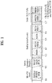
- FIG. 1 is a diagram illustrating physical channels and a signal transmission method using the physical channels, which may be used in various embodiments.
- the UE When a UE is powered on or enters a new cell, the UE performs initial cell search (S11).
- the initial cell search involves acquisition of synchronization to a BS. Specifically, the UE synchronizes its timing to the base station and acquires information such as a cell identifier (ID) by receiving a primary synchronization channel (P-SCH) and a secondary synchronization channel (S-SCH) from the BS.
- ID cell identifier
- P-SCH primary synchronization channel
- S-SCH secondary synchronization channel
- the UE may acquire information broadcast in the cell by receiving a physical broadcast channel (PBCH) from the base station.
- PBCH physical broadcast channel
- the UE may monitor a DL channel state by receiving a downlink reference signal (DL RS).
- DL RS downlink reference signal
- the UE may acquire more detailed system information by receiving a physical downlink control channel (PDCCH) and receiving on a physical downlink shared channel (PDSCH) based on information of the PDCCH (S12).
- PDCCH physical downlink control channel
- PDSCH physical downlink shared channel
- the UE may perform a random access procedure with the eNB (S13 to S16).
- the UE may transmit a preamble on a physical random access channel (PRACH) (S13) and may receive a PDCCH and a random access response (RAR) for the preamble on a PDSCH related to the PDCCH (S14).
- PRACH physical random access channel
- RAR random access response
- the UE may transmit a PUSCH by using scheduling information in the RAR (S15), and perform a contention resolution procedure including reception of a PDCCH signal and a PDSCH signal corresponding to the PDCCH signal (S16).
- steps S13 and S15 may be performed in one operation for a UE transmission
- steps S14 and S16 may be performed in one operation for a BS transmission.
- the UE may receive a PDCCH and/or a PDSCH from the BS (S17) and transmit a physical uplink shared channel (PUSCH) and/or a physical uplink control channel (PUCCH) to the BS (S18), in a general UL/DL signal transmission procedure.
- PUSCH physical uplink shared channel
- PUCCH physical uplink control channel
- the UCI includes a hybrid automatic repeat and request acknowledgement/negative acknowledgement (HARQ-ACK/NACK), a scheduling request (SR), a channel quality indicator (CQI), a precoding matrix index (PMI), a rank indicator (RI), etc.
- HARQ-ACK/NACK hybrid automatic repeat and request acknowledgement/negative acknowledgement
- SR scheduling request
- CQI channel quality indicator
- PMI precoding matrix index
- RI rank indicator
- UCI is transmitted periodically on a PUCCH.
- control information and traffic data may be transmitted on a PUSCH.
- the UCI may be transmitted aperiodically on the PUSCH, upon receipt of a request/command from a network.
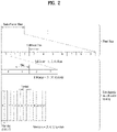
- FIG. 2 is a diagram illustrating a radio frame structure in an NR system to which various embodiments of the present disclosure are applicable.
- the NR system may support multiple numerologies.
- a numerology may be defined by a subcarrier spacing (SCS) and a cyclic prefix (CP) overhead.
- Multiple SCSs may be derived by scaling a default SCS by an integer N (or ⁇ ). Further, even though it is assumed that a very small SCS is not used in a very high carrier frequency, a numerology to be used may be selected independently of the frequency band of a cell. Further, the NR system may support various frame structures according to multiple numerologies.
- OFDM numerologies and frame structures which may be considered for the NR system.
- Multiple OFDM numerologies supported by the NR system may be defined as listed in Table 1.
- multiple numerologies e.g., SCSs
- SCS single numerologies
- a wide area in cellular bands is supported for an SCS of 15kHz
- a dense-urban area is supported for an SCS of 15kHz
- a dense-urban area is supported for an SCS of 30kHz/60kHz
- a larger bandwidth than 24.25GHz is supported for an SCS of 60kHz or more, to overcome phase noise.
- An NR frequency band is defined by two types of frequency ranges, FR1 and FR2.
- FR1 may be a sub-6GHz range
- FR2 may be an above-6GHz range, that is, a millimeter wave (mmWave) band.
- mmWave millimeter wave
- Table 2 defines the NR frequency band, by way of example.
- Frequency range designation Corresponding frequency range Subcarrier Spacing FR1 410 MHz-7125 MHz 15, 30, 60kHz FR2 24250 MHz - 52600 MHz 60, 120, 240kHz
- slots are numbered with n ⁇ s ⁇ ⁇ 0,..., N slot, ⁇ subframe -1 ⁇ in an increasing order in a subframe, and with n ⁇ s,f ⁇ ⁇ 0,..., N slot, ⁇ frame -1 ⁇ in an increasing order in a radio frame.
- One slot includes N ⁇ symb consecutive OFDM symbols, and N ⁇ symb depends on a CP.
- the start of a slot n ⁇ s in a subframe is aligned in time with the start of an OFDM symbol n ⁇ s ⁇ N ⁇ symb in the same subframe.
- Table 3 lists the number of symbols per slot, the number of slots per frame, and the number of slots per subframe, for each SCS in a normal CP case
- Table 4 lists the number of symbols per slot, the number of slots per frame, and the number of slots per subframe, for each SCS in an extended CP case.
- N slot symb represents the number of symbols in a slot
- N frame represents the number of slots in a frame
- N subframe represents the number of slots in a subframe
- different OFDM(A) numerologies may be configured for a plurality of cells which are aggregated for one UE. Accordingly, the (absolute time) period of a time resource including the same number of symbols (e.g., a subframe (SF), a slot, or a TTI) (generically referred to as a time unit (TU), for convenience) may be configured differently for the aggregated cells.
- a time resource including the same number of symbols e.g., a subframe (SF), a slot, or a TTI
- TU time unit
- One subframe ⁇ 1, 2, 4 ⁇ slots in FIG. 2 , which is exemplary, and the number of slot(s) which may be included in one subframe is defined as listed in Table 3 or Table 4.
- a mini-slot may include 2, 4 or 7 symbols, fewer symbols than 2, or more symbols than 7.
- FIG. 3 is a diagram illustrating a slot structure in an NR system to which various embodiments of the present disclosure are applicable.
- one slot includes a plurality of symbols in the time domain.
- one slot includes 7 symbols in a normal CP case and 6 symbols in an extended CP case.
- a carrier includes a plurality of subcarriers in the frequency domain.
- An RB is defined by a plurality of (e.g., 12) consecutive subcarriers in the frequency domain.
- a bandwidth part (BWP), which is defined by a plurality of consecutive (P)RBs in the frequency domain, may correspond to one numerology (e.g., SCS, CP length, and so on).
- numerology e.g., SCS, CP length, and so on.
- a carrier may include up to N (e.g., 5) BWPs. Data communication may be conducted in an activated BWP, and only one BWP may be activated for one UE.
- N e.g., 5
- BWP Band-WP
- Each element is referred to as an RE, to which one complex symbol may be mapped.
- FIG. 4 is a diagram illustrating an example of mapping physical channels to a slot to which various embodiments of the present disclosure are applicable.
- DL control channel(s), DL or UL data, and UL control channel(s) may all be included in one slot.
- the first N symbols (hereinafter, referred to as a DL control region) of the slot may be used to transmit a DL control channel
- the last M symbols (hereinafter, referred to as a UL control region) of the slot may be used to transmit a UL control channel.
- N and M are each an integer greater than or equal to 0.
- a resource region hereinafter, referred to as a data region
- a time gap for DL-to-UL or UL-to-DL switching may exist between the control region and the data region.
- a PDCCH may be transmitted in the DL control region
- a PDSCH may be transmitted in the DL data region.
- the BS transmits related signals to the UE on DL channels as described below, and the UE receives the related signals from the BS on the DL channels.
- PDSCH Physical downlink shared channel
- the PDSCH conveys DL data (e.g., DL-shared channel transport block (DL-SCH TB)) and uses a modulation scheme such as quadrature phase shift keying (QPSK), 16-ary quadrature amplitude modulation (16QAM), 64QAM, or 256QAM.
- a TB is encoded into a codeword.
- the PDSCH may deliver up to two codewords. Scrambling and modulation mapping are performed on a codeword basis, and modulation symbols generated from each codeword are mapped to one or more layers (layer mapping). Each layer together with a demodulation reference signal (DMRS) is mapped to resources, generated as an OFDM symbol signal, and transmitted through a corresponding antenna port.
- DMRS demodulation reference signal
- PDCCH Physical downlink control channel
- the PDCCH may deliver downlink control information (DCI), for example, DL data scheduling information, UL data scheduling information, and so on.
- DCI downlink control information
- the PUCCH may deliver uplink control information (UCI), for example, an acknowledgement/negative acknowledgement (ACK/NACK) information for DL data, channel state information (CSI), a scheduling request (SR), and so on.
- UCI downlink control information
- ACK/NACK acknowledgement/negative acknowledgement
- CSI channel state information
- SR scheduling request
- the PDCCH carries downlink control information (DCI) and is modulated in quadrature phase shift keying (QPSK).
- DCI downlink control information
- QPSK quadrature phase shift keying
- One PDCCH includes 1, 2, 4, 8, or 16 control channel elements (CCEs) according to an aggregation level (AL).
- CCE includes 6 resource element groups (REGs).
- REG is defined by one OFDM symbol by one (P)RB.
- the PDCCH is transmitted in a control resource set (CORESET).
- a CORESET is defined as a set of REGs having a given numerology (e.g., SCS, CP length, and so on).
- a plurality of CORESETs for one UE may overlap with each other in the time/frequency domain.
- a CORESET may be configured by system information (e.g., a master information block (MIB)) or by UE-specific higher layer (RRC) signaling.
- MIB master information block
- RRC UE-specific higher layer
- the number of RBs and the number of symbols (up to 3 symbols) included in a CORESET may be configured by higher-layer signaling.
- the UE acquires DCI delivered on a PDCCH by decoding (so-called blind decoding) a set of PDCCH candidates.
- a set of PDCCH candidates decoded by a UE are defined as a PDCCH search space set.
- a search space set may be a common search space (CSS) or a UE-specific search space (USS).
- the UE may acquire DCI by monitoring PDCCH candidates in one or more search space sets configured by an MIB or higher-layer signaling.
- Type Search Space RNTI Use Case Type0-PDCCH Common SI-RNTI on a primary cell SIB Decoding Type0A-PDCCH Common SI-RNTI on a primary cell SIB Decoding Typc1-PDCCH Common RA-RNTI or TC-RNTI on a primary cell Msg2, Msg4 decoding in RACH Type2-PDCCH Common P-RNTI on a primary cell Paging Decoding Type3-PDCCH Common INT-RNTI, SFI-RNTI, TPC-PUSCH-RNTI, TPC-PUCCH-RNTI, TPC-SRS-RNTI, C-RNTI, MCS-C-RNTI, or CS-RNTI(s) UE Specific C-RNTI, or MCS-C-RNTI, or CS-RNTI(s) User specific PDSCII decoding
- Table 6 lists exemplary DCI formats transmitted on the PDCCH.
- DCI format 0_0 may be used to schedule a TB-based (or TB-level) PUSCH
- DCI format 0_1 may be used to schedule a TB-based (or TB-level) PUSCH or a code block group (CBG)-based (or CBG-level) PUSCH
- DCI format 1_0 may be used to schedule a TB-based (or TB-level) PDSCH
- DCI format 1_1 may be used to schedule a TB-based (or TB-level) PDSCH or a CBG-based (or CBG-level) PDSCH.
- DCI format 2_0 is used to deliver dynamic slot format information (e.g., a dynamic slot format indicator (SFI)) to the UE
- DCI format 2_1 is used to deliver DL preemption information to the UE.
- DCI format 2_0 and/or DCI format 2_1 may be delivered to the UEs of a group on a group common PDCCH (GC-PDCCH) which is a PDCCH directed to a group of UEs.
- GC-PDCCH group common PDCCH
- the UE transmits related signals on later-described UL channels to the BS, and the BS receives the related signals on the UL channels from the UE.
- PUSCH Physical uplink shared channel
- the PUSCH delivers UL data (e.g., a UL-shared channel transport block (UL-SCH TB)) and/or UCI, in cyclic prefix-orthogonal frequency division multiplexing (CP-OFDM) waveforms or discrete Fourier transform-spread-orthogonal division multiplexing (DFT-s-OFDM) waveforms.
- CP-OFDM cyclic prefix-orthogonal frequency division multiplexing
- DFT-s-OFDM discrete Fourier transform-spread-orthogonal division multiplexing
- the UE may transmit the PUSCH in CP-OFDM waveforms
- transform precoding is possible (e.g., transform precoding is enabled)
- the UE may transmit the PUSCH in CP-OFDM waveforms or DFT-s-OFDM waveforms.
- the PUSCH transmission may be scheduled dynamically by a UL grant in DCI or semi-statically by higher-layer signaling (e.g., RRC signaling) (and/or layer 1 (L1) signaling (e.g., a PDCCH)) (a configured grant).
- the PUSCH transmission may be performed in a codebook-based or non-codebook-based manner.
- PUCCH Physical uplink control channel
- the PUCCH delivers UCI, an HARQ-ACK, and/or an SR and is classified as a short PUCCH or a long PUCCH according to the transmission duration of the PUCCH.
- Table 7 lists exemplary PUCCH formats. [Table 7] PUCCH format Length in OFDM symbols N symb PUCCH Number of bits Usage Etc 0 1 - 2 ⁇ 2 HARQ, SR Sequence selection 1 4 - 14 ⁇ 2 HARQ, [SR] Sequence modulation 2 1 - 2 >2 HARQ, CSI, [SR] CP-OFDM 3 4 - 14 >2 HARQ, CSI, [SR] DFT-s-OFDM (no UE multiplexing) 4 4 - 14 >2 HARQ, CSI, [SR] DFT-s-OFDM (Pre DFT OCC)
- PUCCH format 0 conveys UCI of up to 2 bits and is mapped in a sequencebased manner, for transmission. Specifically, the UE transmits specific UCI to the BS by transmitting one of a plurality of sequences on a PUCCH of PUCCH format 0. Only when the UE transmits a positive SR, the UE transmits the PUCCH of PUCCH format 0 in a PUCCH resource for a corresponding SR configuration.
- PUCCH format 1 conveys UCI of up to 2 bits and modulation symbols of the UCI are spread with an OCC (which is configured differently whether frequency hopping is performed) in the time domain.
- the DMRS is transmitted in a symbol in which a modulation symbol is not transmitted (i.e., transmitted in time division multiplexing (TDM)).
- PUCCH format 2 conveys UCI of more than 2 bits and modulation symbols of the DCI are transmitted in frequency division multiplexing (FDM) with the DMRS.
- the DMRS is located in symbols #1, #4, #7, and #10 of a given RB with a density of 1/3.
- a pseudo noise (PN) sequence is used for a DMRS sequence.
- frequency hopping may be activated.
- PUCCH format 3 does not support UE multiplexing in the same PRBS, and conveys UCI of more than 2 bits. In other words, PUCCH resources of PUCCH format 3 do not include an OCC. Modulation symbols are transmitted in TDM with the DMRS.
- PUCCH format 4 supports multiplexing of up to 4 UEs in the same PRBS, and conveys UCI of more than 2 bits.
- PUCCH resources of PUCCH format 3 includes an OCC. Modulation symbols are transmitted in TDM with the DMRS.
- Section 1 A detailed description will be given of various embodiments based on the above technical ideas.
- the afore-described contents of Section 1 is applicable to various embodiments described below. For example, operations, functions, terminologies, and so on which are not defined in various embodiments may be performed and described based on Section 1.
- DFT-S-OFDM may be replaced with single carrier (SC)-OFDM/SC-FDMA or the like.
- a signal processing procedure of a receiving end/transmitting end may be configured as a reverse of the configuration of a signal processing procedure of the transmitting end/receiving end according to various embodiments, and this may also be included in various embodiments.
- Various embodiments may relate to single-carrier-based transmission and reception within a mmWave frequency band.
- a DFT block size may be limited such that it becomes 1/N (N being an integer/natural number) of the ratio of the DFT block size to an IFFT size (and/or IFFT block size).
- the IFFT size may determine a sampling frequency.
- the IFFT size may be determined based on the sampling frequency.
- the DFT size may determine the number of allocated subcarriers.
- the DFT size may be determined based on the number of allocated subcarriers. For example, when spectrum shaping is not specifically defined in the frequency domain, the DFT size and/or the number of allocated subcarriers may correspond to an occupied bandwidth.
- spectrum shaping may be used through resources other than a region to which a DFT output is mapped.
- a PAPR of a transmission signal may be reduced, and thus, the efficiency of a power amplifier may be increased.
- a plurality of DFT blocks having a limited size may be used. According to various embodiments, actual frequency use efficiency may be increased.
- a method of setting the same limit (as the DFT block size) on a resource block size and/or making the resource block size and the DFT block size inconsistent with each other may be provided.
- a frequency band of 52.6 GHz or higher may be defined as frequency range 4 (FR4).
- downlink transmission is performed based on OFDM/OFDMA (e.g., cyclic prefix (CP)-OFDM) and uplink transmission is performed based on DFT-s-OFDM.
- OFDM/OFDMA e.g., cyclic prefix (CP)-OFDM
- DFT-s-OFDM Downlink transmission is performed based on DFT-s-OFDM.
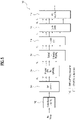
- FIG. 5 is a diagram illustrating an example of a structure of a transmitter to which various embodiments are applicable.
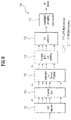
- FIG. 6 is a diagram illustrating an example of a structure of a receiver to which various embodiments are applicable.
- a difference between DFT-s-OFDM(A) and OFDM(A) in the transmitter structure is that DFT precoding 706 is applied before IFFT processing 710, and a difference between DFT-s-OFDM(A) and OFDM(A) in the receiver structure is that IFFT postcoding 728 is applied after FFT processing 724.
- the signal processing in FIGS. 5 and 6 will be described based on DFT-s-OFDM(A), and if signal processing 706 and 728 indicated by dotted lines is omitted, it corresponds to OFDM(A).
- a bit stream is modulated into a data symbol sequence (702).
- the serial data symbol sequence is then converted into N u parallel data symbol sequences (704).
- the N u -length parallel data symbol sequences are converted into N u -length frequency domain sequences through FFT processing of the same size (706).
- FFT processing may be performed through N u -point DFT processing.
- FFT is used interchangeably with DFT
- DFT processing is used interchangeably with DFT spreading or DFT precoding.
- the N u -length frequency domain sequences are mapped to N u subcarriers allocated among Nc subcarriers, and 0 is padded to the remaining N c -N u subcarriers (708).
- the sequences mapped to the Nc subcarriers are converted into time-domain sequences having a length of Nc through Nc-point IFFT processing (710).
- a CP is constructed by copying the last N p samples from the time-domain sequences and adding them to the beginning of the sequences (712).
- the generated time-domain sequences correspond to one transmission symbol and are converted into a serial sequence through a parallel/serial converter (S714).
- the serial sequence is transmitted to a receiving end through frequency up-conversion or the like.
- Another user transmits data by being allocated available subcarriers from among the N c -N u subcarriers remaining after being used by the previous user.
- a receiving end 720 includes a serial/parallel converter 722, an Nc-point FFT module 724, a subcarrier-to-symbol mapping module 726, a N u -point DFT despreading module 728, a parallel/serial converter 730, and a constellation demapping module 732. Since the signal processing procedure of the receiving end 720 is the reverse to that of the transmitting end 700, refer to FIG. 5 and related description for details.
- radio frequency In general, as a radio frequency (RF) increases to a high frequency band, radio wave characteristics such as signal magnitude attenuation characteristics and characteristics of a device implementing the same may become considerably different. In particular, as the frequency increases, the efficiency and phase noise characteristics of an amplifier such as a power amplifier may considerably deteriorate.
- a single-carrier transmission system rather than a multi-carrier transmission system such as OFDM has an advantage in terms of system implementation in the FR4 band.
- the frequency band in which the system operates such as the FR4 band
- application of a waveform with a low PAPR to downlink may be considered when the linearity of the power amplifier is considered in terms of transmission of a base station as well as a UE. Therefore, according to various embodiments, DFT-s-OFDM may be considered as an example of a single carrier transmission system as a (downlink/uplink) transmission method in the FR4 band.
- FIG. 7 is a diagram illustrating an example of a DFT-s-OFDM system to which various embodiments are applicable.
- FIG. 7 shows an example of a transmission/reception structure of a general DFT-s-OFDM system applicable to various embodiments.
- a bit stream and/or a signal may be channel-coded and modulated to be DFT-precoded in a transmitting end, resource mapping is performed on the DFT-precoded signal, IFFT is performed thereon, frequency up-conversion is performed therein, and the resultant signal is transmitted through a channel.
- Signal processing at a receiving end may be configured as a reverse of the process at the transmitting end. After frequency down-conversion is performed on the signal received through the channel at the receiving end, FFT may be performed thereon, resource demapping may be performed thereon, and then an equalization operation may be performed thereon.
- IDFT may be performed on a recovered signal according to equalization, demodulation (e.g., loglikelihood ratio (LLR) extraction or the like) may be performed thereon, and then channel decoding may be performed to obtain the bit stream and/or the signal at the receiving end.
- demodulation e.g., loglikelihood ratio (LLR) extraction or the like
- channel decoding may be performed to obtain the bit stream and/or the signal at the receiving end.
- a DFT-precoded signal may be mapped to the frequency domain to be transmitted, and then IFFT is performed thereon, and a configured baseband signal may be frequency up-converted and transmitted.
- a receiver may perform reception through a reverse process of a transmission process. For example, in the reception process, an equalization operation for removing interference between signals distorted through a channel may be performed. For efficient implementation of an equalizer, the equalization operation and the like may be performed in the frequency domain. For example, a process of performing equalization after FFT and obtaining a modulated symbol through DFT with respect to a recovered signal may correspond thereto. This is because, when a delay profile of a channel is long, equalization in the time domain (and/or the time domain and/or the time axis) requires a very large matrix operation and thus it is inefficient to implement equalization.
- equalization When equalization is implemented in the frequency domain (and/or frequency domain and/or frequency axis) in a multi-carrier system, only 1-tap equalization may be performed per subcarrier. In DFT-s-OFDM, equalization in the frequency domain may also be implemented in this way.
- FIG. 8 is a diagram illustrating an example of a DFT-s-OFDM system according to various embodiments.
- FIG. 8 shows an example of a transmission/reception structure of a DFT-s-OFDM system having low complexity according to various embodiments.
- a bit stream and/or a signal may be channel-coded and modulated to be upsampled, a waveform shaping filter may be applied to the upsampled signal, frequency up-conversion may be performed thereon, and then the resultant signal may be transmitted through a channel.
- a signal processing procedure at a receiving end may be configured as a reverse process to that of the transmitting end.
- time-domain equalization may be performed thereon, downsampling may be performed thereon, demodulation (e.g., LLR extraction or the like) may be performed thereon, and then channel decoding may be performed to obtain the bit stream and/or the signal.
- demodulation e.g., LLR extraction or the like
- a series of operations/functions corresponding to DFT, resource mapping, and/or IFFT may be replaced with a series of operations/functions such as upsampling and/or a waveform shaping filter in the transmitter, and a series of operations/functions corresponding to resource demapping, equalization and/or IDFT may be replaced with a series of operations/functions such as time-domain equalization and/or downsampling in the receiver.
- a transmitted radio wave may be received through various paths, and thus a delay profile of several to tens of samples may be generated. Accordingly, it may be required to remove intersymbol interference caused by multipath propagation with respect to a received signal, and an equalizer may perform removal of intersymbol interference.
- equalization is performed in the time domain in a single-carrier system
- the amount of matrix computation greatly increases in proportion to a delay profile and complexity may increase.
- equalization is performed in the frequency domain as shown in FIG. 7 .
- a frequency-domain equalizer frequency-domain equalizer, FD-equalizer/FD-equalization
- an operation corresponding to FFT/IDFT is additionally performed but an equalizer is implemented in a 1-tap form for each subcarrier, and thus a large amount of matrix operation can be eliminated.
- the FD-equalizer may exhibit more advantageous characteristics than the TD-equalizer in terms of complexity.
- a transmitting/receiving method using a narrow beam in the space through beamforming to secure coverage may be considered.
- a high-frequency band signal such as mmWave may exhibit propagation characteristics in which signal attenuation due to reflection and transmission is very large.
- the amount of matrix computation necessary for the TD-equalizer decreases, and a reverse phenomenon in which the amount of FFT/IDFT computation of the FD-equalizer increases may occur.
- a data rate may considerably increase because communication is performed through a broadband.
- the amount of computation of a receiver may act as a very important factor in system implementation.
- channel decoding may need to be performed using samples obtained by executing the TD-equalizer.
- a sample obtained through the TD-equalizer may need to correspond to a modulated symbol generated at a transmitting end.
- the output of the TD-equalizer may show that a modulated symbol is sampled at a position where the modulated symbol is not zero-crossing with an adjacent symbol.
- the size of IFFT is 2048 but the number of subcarriers actually used for signal transmission and reception thereamong may be 1200.
- 1200 modulated symbols can appear over 2048 samples by the TD-equalizer. Accordingly, there may be problems that modulated symbols need to be obtained through IDFT with respect to samples of the TD-equalizer, and IDFT needs to be performed for every OFDM symbol.
- the size of the DFT (and/or IDFT) block can be limited to a specific value such that the above-described problems can be solved.
- modulated symbols can be obtained through down sampling without performing IDFT, and thus complexity can be reduced.
- a DFT (and/or IDFT) block size the number of subcarriers used for transmission of a modulated symbol at the transmitting end
- an IFFT (and/or FFT) block size of 2048 downsampling in the time domain is performed (and/or downsampling is performed and then equalization in the time domain is performed) instead of IDFT for samples obtained from the output of the TD-equalizer, and thus a receiver with reduced complexity can be implemented.
- operations/functions corresponding to DFT, resource mapping and/or IFFT may be replaced with upsampling and/or waveform shaping filtering operations/functions, and thus a transmitter with reduced complexity can be implemented.
- a DFT block size (e.g., this can determine the number of allocated subcarriers, and in particular, if spectrum shaping or the like is not defined in the frequency domain, for example, this may correspond to an occupied bandwidth) may be limited such that the ratio of the DFT block size to an IFFT size (for example, this can determine a sampling frequency) becomes 1/N (N being an integer, a non-zero integer, or a natural number).
- the DFT block size corresponding to an IFFT size of 2048 may be one or more of 2048, 1024, 512, 256, 128, 64, 32, 16, 8, 4, 2, 1, and the like.
- the DFT block size may be dynamically changed.
- the DFT block size may be dynamically changed while the above-described condition (1/N condition) is satisfied.
- information on the DFT block size may be transmitted/received through a control channel carrying scheduling information (e.g., DCI in LTE/NR).
- scheduling information e.g., DCI in LTE/NR.
- a maximum DFT block size and/or a configurable set may be configured for a UE in a call setup stage and/or the maximum DFT block size and/or the configurable set may be predefined such that the UE can preset a sampling frequency and/or a filter set configuration for downsampling.
- a frequency band effectively used by the system may be limited.
- a carrier assigned a frequency of 320 MHz uses the numerology of ⁇ 240 kHz SCS, 2048 IFFT size (sampling frequency: 491.52 MHz), 1024 DFT block size (the number of allocated subcarriers: 1024), occupied bandwidth: 245.76 MHz ⁇
- a method of obtaining an additional system gain and/or increasing frequency use efficiency by using an extra frequency band for a system having low complexity may be considered.
- FIG. 9 is a diagram illustrating an example of spectrum shaping according to various embodiments.
- FIG. 9 shows an example of frequency domain spectrum shaping of a DFT-s-OFDM system according to various embodiments.
- the x-axis is the frequency domain and the y-axis is an amplitude.
- a spectrum shaping method for increasing frequency use efficiency in a case where numerology according to the above-described various embodiments is set may be provided.
- the actual system may use spectrum shaping (e.g., spectrum shaping such as triangular shaping) in the frequency domain to reduce a PAPR of a transmitted signal, thereby increasing the efficiency of a power amplifier.
- spectrum shaping e.g., spectrum shaping such as triangular shaping
- a symbol is copied to the remaining region, and spectrum shaping may be performed based thereon.
- spectrum shaping may be performed based thereon.
- symbols corresponding to 1024 are copied to at least a part of a band except for a guard band for an adjacent frequency band, and spectrum shaping may be performed based thereon.
- a filter for spectrum shaping a Hamming window, a squared root-raised cosine (SRRC) filter, or the like may be used, unlike the example shown in FIG. 9 .
- SRRC squared root-raised cosine
- FIG. 10 is a diagram illustrating an example of a spectrum shaping implementation according to various embodiments.
- spectrum shaping as shown in FIG. 9 may be performed on DFT output, which may be implemented in the frequency domain.
- a bit stream and/or a signal may be channel-coded and modulated to be DFT-precoded, and after resource mapping is performed on the DFT-precoded signal, spectrum shaping may be performed thereon, IFFT may be performed thereon, and then the resultant signal may be frequency up-converted and transmitted.
- a spectrum shaping filter may be implemented in the time domain.
- a bit stream and/or a signal may be channel-coded, modulated and upsampled in the transmitting end, and then the shaping filter may be applied thereto and then the resultant signal may be frequency-up-converted and transmitted.
- this operation may be structurally the same as that of the transmitter when frequency domain spectrum shaping is not used, as illustrated in FIG. 8 .
- the waveform shaping filter may be configured such that a spectrum shaping response defined in the frequency domain is reflected.
- the actual frequency use efficiency is the same, but the frequency spectrum occupancy is increased, thereby reducing a PAPR of a transmitted signal and increasing the efficiency of the power amplifier.
- a frequency efficiency of about 77% may be obtained in the case of a 2048 IFFT block size and a 1024 DFT block size.
- a method capable of further increasing such frequency efficiency may be provided.
- the size of each DFT block may be set such that the condition according to the above-described various embodiments (the condition that the DFT block size is set such that the ratio of the DFT block size to the IFFT size (determining the sampling frequency) becomes 1/N) is satisfied, and thus low complexity of the receiver can be maintained.
- the DFT block size corresponding to each of the multiple DFT blocks may be one or more of 2048, 1024, 512, 256, 128, 64, 32, 16, 8, 4, 2, and 1.
- the sum of the sizes of the multiple DFT blocks may be less than or equal to the size of the allocated bandwidth. For example, when the number of subcarriers used is 1200, the sum of the sizes of the multiple DFT blocks may be 1200 or less.
- FIG. 11 is a diagram illustrating an example of a transmission method using multiple DFT blocks according to various embodiments.
- bit streams and/or signals to be input to different DFT blocks may be channel-coded and modulated, input to different DFT blocks (DFT block having a size of K1 and DFT block having a size of K2), and DFT-precoded, and after resource mapping is performed on the output of each DFT block, IFFT may be performed thereon and the resultant signals may be frequency up-converted and transmitted through a channel.
- resource mapping a resource location in a frequency domain corresponding to DFT block #1 and a resource location in a frequency domain corresponding to DFT block #2 may be preset.
- the output of DFT block #1 (and/or K1 samples corresponding to DFT block #1) and the output of DFT block #2 (and/or K2 samples corresponding to DFT block #2) may be mapped contiguously and/or discontinuously in the frequency domain.
- mapping operation in the frequency domain may be implemented as frequency shifting.
- each bit stream and/or signal to be frequency-shifted in the transmitting end may be channel-coded, modulated and upsampled, a waveform shaping filter may be applied thereto, and frequency shift may be applied thereto.
- frequency up-conversion may be applied thereto.
- the DFT block size (e.g., K1 and K2 in FIG. 11 ) may be semi-statically set by RRC configuration and/or may be dynamically indicated through a control channel according to the amount of data transmitted.
- the center frequency in the transmitted frequency region may be semi-statically set even if the DFT block size is variable.
- a frequency region to which each DFT block is mapped may be preset through the above-described setting method.
- a DFT block mapped to a region through which a UE receives a signal may be semi-statically set according to a traffic load state of the UE and/or may be dynamically indicated through a control channel.
- signals may be simultaneously received through two DFT block sizes (and/or two or more DFT block sizes) according to UE capability.
- resources may be variably allocated depending on the amount of data to be transmitted to the UE.
- TDM which may mean a method of allocating only a part to a UE at the front end of a DFT block
- FDM which is a method of varying a frequency band allocated on a frequency and may mean varying the DFT block size
- a resource block may be defined and a method of allocating resources in units of RBs may be used in LTE and/or NR systems.
- the ratio of a sampling frequency to an allocated bandwidth obtained from the number of allocated subcarriers may be set such that it is maintained at an integer ratio of 1/K (K may be an integer/non-zero integer/natural number).
- the size of the resource block also satisfies this constraint (e.g., the ratio of the sampling frequency to the frequency bandwidth of the RB may be 1/K (K being an integer/non-zero integer/natural number), and thus dynamic RB allocation can be performed.
- the sampling frequency is set such that the IFFT size becomes 2 ⁇ n (2 n )
- the number of subcarriers constituting the RB may be defined such that it becomes the power of 2 (2 ⁇ m, 2 m ) (m and n being integers equal to or greater than 0).
- a method of interpreting the actual number of effective subcarriers corresponding to RBs allocated according to a method defined/set/appointed in advance between a base station and a UE while maintaining the size of the RB as a size according to the conventional LTE and/or NR system may be provided.
- the RB size is maintained at 12 (subcarriers), and the method in (1) according to the various embodiments described above may be applied to the DFT block size.
- the DFT block size may not be the same as the size of the number of allocated RBs (and/or subcarriers), unlike a case in the conventional LTE and/or NR systems.
- a smallest value satisfying the method according to the various embodiments described above in (1) among values larger than the number of allocated RBs (and/or subcarriers) may be adopted as the DFT block size.
- the DFT block size may differ from the size of a symbol input as a DFT input. According to various embodiments, one or more of the following methods may be considered to match these (that is, to match the DFT block size and the size of a symbol input as a DFT input).
- the resource block size may be maintained as 12 (subcarriers) and the method according to the various embodiments described above in (1) may be applied to the DFT block size.
- the DFT block size may not be the same as the number of allocated RBs (and/or subcarriers), unlike a case in conventional LTE and/or NR systems, and a largest value satisfying the method according to the various embodiments described above in (1) among values smaller than the number of allocated RBs (and/or subcarriers) may be adopted as the DFT block size, for example.
- the number of symbols input to actual DFT may be limited by the DFT size.
- one or more of the following methods may be considered in consideration of the fact that a signal output from DFT becomes smaller than the number of actually allocated subcarriers.
- the number of subcarriers used for actual transmission and reception may be 1024 among values smaller than 1080 according to the method proposed in (1).
- the DFT size becomes 1024, for example, the signal output from DFT may be mapped to the 1080 subcarriers, and zero padding may be performed on 56 subcarriers and/or a PAPR reduction effect can be obtained through spectrum shaping as in the example of FIG. 9 .
- the RB size may be maintained as 12 (subcarriers), and the method according to the various embodiments described above in (1) may be applied to the DFT block size.
- the DFT block size may not be the same as the number of allocated RBs (and/or subcarriers), unlike a case in the conventional LTE and/or NR systems, as in method A.
- the largest value satisfying the method according to the various embodiments described above in (1) among values smaller than the number of allocated RBs (and/or subcarriers) (hereinafter referred to as X) may be adopted as the DFT block size.
- the signal output from DFT is mapped to Y RBs as in method B, and one or more of the following methods may be considered because the number of DFT outputs is small.
- a control channel for implementation of low complexity of a DFT-s-OFDM system, it may be desirable to transmit/receive a control channel through a DFT block size and/or a frequency region set such that the constraints according to the various embodiments described above in (1) are satisfied.
- a control channel may be transmitted and received in a control resource set (CORESET), which is a resource region for control channel transmission, and the DFT/IDFT block size may correspond to the size of a frequency region constituting the CORESET.
- CORESET control resource set
- the frequency bandwidth of CORESET needs to be set within a preset maximum DFT/IDFT block size as in the various embodiments described above in (1).
- the frequency region of a set data channel may have the same center frequency as a frequency region in which a control channel is transmitted and received (frequency region constituting CORESET), and only a value smaller than the DFT/IDFT block size for transmission/reception of the control channel and/or a preset maximum DFT block size be indicated as a DFT/IDFT block size for the data channel.
- a value smaller than the DFT/IDFT block size for transmission/reception of the control channel and/or a preset maximum DFT block size be indicated as a DFT/IDFT block size for the data channel.
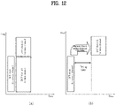
- FIG. 12 is a diagram illustrating an example of a configuration of a control channel and a data channel according to various embodiments.
- the data channel is configured through a plurality of DFT/IDFT blocks (DFT/IDFT block #1 for the data channel and DFT/IDFT block #2 for the data channel) for transmission and reception of the data channel as in the various embodiments according to (3), but the control channel is configured through only one DFT/IDFT block.
- the plurality of DFT/IDFT blocks for the data channel may be configured within one carrier), information about the frequency band (frequency domain resource allocation information) as well as a DFT block size for transmission of the data channel may be known through the control channel.
- a timing gap for reconfiguring an RF component may be required depending on the UE capability (refer to FIG. 12(b) ).
- the size of the DFT/IDFT block for the control channel may match the maximum size of DFT block #1 for the data channel.
- the DFT/IDFT block for the control channel and DFT/IDFT block #2 for the data channel may be configured at different frequency resource locations within one carrier.
- FIG. 13 is a diagram briefly illustrating an operating method of a first apparatus and a second apparatus according to various embodiments.
- FIG. 14 is a flowchart illustrating an operating method of the first apparatus according to various embodiments.
- FIG. 15 is a flowchart illustrating an operating method of the second apparatus according to various embodiments.
- the first apparatus may be a base station/UE and the second apparatus may be a UE/base station.
- the first apparatus may acquire/generate a data channel based on DFT-s-OFDM.
- the first apparatus may transmit the data channel, and the second apparatus may receive the same.
- the second apparatus may acquire data based on the data channel.
- the data channel may be mapped to one or more first subcarriers in the frequency domain.
- the size of a first DFT/IDFT block related to the one or more first subcarriers may be 1/N times the size of an IFFT/FFT block related to a preset sampling frequency, and N may be a natural number.
- data obtained from the second apparatus may be obtained based on applying FFT to the data channel and then applying IDFT thereto, or may be obtained based on applying downsampling to the data channel.
- the data obtainable based on applying FFT to the data channel and then applying IDFT thereto and the data obtainable based on applying downsampling to the data channel may be the same data.
- a data channel obtainable based on applying DFT and then applying IFFT and a data channel obtainable based on applying upsampling may be the same data channel.
- a rule may be defined such that the BS informs the UE of information as to whether the proposed methods are applied (or information about rules of the proposed methods) through a predefined signal (e.g., a physical layer signal or a higher-layer signal).
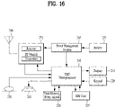
- FIG. 16 is a diagram illustrating devices that implement various embodiments of the present disclosure.
- the devices illustrated in FIG. 16 may be a UE and/or a BS (e.g., eNB or gNB) adapted to perform the afore-described mechanisms, or any devices performing the same operation.
- a BS e.g., eNB or gNB
- the device may include a digital signal processor (DSP)/microprocessor 210 and a radio frequency (RF) module (transceiver) 235.
- the DSP/microprocessor 210 is electrically coupled to the transceiver 235 and controls the transceiver 235.
- the device may further include a power management module 205, a battery 255, a display 215, a keypad 220, a SIM card 225, a memory device 230, an antenna 240, a speaker 245, and an input device 250, depending on a designer's selection.
- FIG. 16 may illustrate a UE including a receiver 235 configured to receive a request message from a network and a transmitter 235 configured to transmit timing transmission/reception timing information to the network. These receiver and transmitter may form the transceiver 235.
- the UE may further include a processor 210 coupled to the transceiver 235.
- FIG. 16 may illustrate a network device including a transmitter 235 configured to transmit a request message to a UE and a receiver 235 configured to receive timing transmission/reception timing information from the UE. These transmitter and receiver may form the transceiver 235.
- the network may further include the processor 210 coupled to the transceiver 235. The processor 210 may calculate latency based on the transmission/reception timing information.
- a processor included in a UE (or a communication device included in the UE) and a BE (or a communication device included in the BS) may operate as follows, while controlling a memory.
- a UE or a BS may include at least one transceiver, at least one memory, and at least one processor coupled to the at least one transceiver and the at least one memory.
- the at least one memory may store instructions causing the at least one processor to perform the following operations.
- a communication device included in the UE or the BS may be configured to include the at least one processor and the at least one memory.
- the communication device may be configured to include the at least one transceiver, or may be configured not to include the at least one transceiver but to be connected to the at least one transceiver.
- the first apparatus may be a base station/UE and the second apparatus may be a UE/base station.
- one or more processors included in the first apparatus may acquire/generate a data channel based on DFT-s-OFDM.
- the one or more processors included in the first apparatus may transmit the data channel.
- the data channel may be mapped to one or more first subcarriers in the frequency domain.
- the size of a first DFT block related to the one or more first subcarriers may be 1/N times the size of an IFFT block related to a preset sampling frequency, and N may be a natural number.
- one or more processors included in the second apparatus may receive a data channel based on DFT-s-OFDM.
- the one or more processors included in the second apparatus may transmit the data channel.
- the data channel may be mapped to one or more first subcarriers in the frequency domain.
- the size of a first IDFT block related to the one or more first subcarriers may be 1/N times the size of an FFT block related to a preset sampling frequency, and N may be a natural number.
- various embodiments of the present disclosure may be implemented in combination.
- the BS and/or the UE according to various embodiments of the present disclosure may perform operations in combination of the embodiments of the afore-described clause 1 to clause 2, unless contradicting with each other.
- FIG. 17 illustrates an exemplary communication system to which various embodiments of the present disclosure are applied.
- a communication system 1 applied to the various embodiments of the present disclosure includes wireless devices, Base Stations (BSs), and a network.
- the wireless devices represent devices performing communication using Radio Access Technology (RAT) (e.g., 5G New RAT (NR)) or Long-Term Evolution (LTE)) and may be referred to as communication/radio/5G devices.
- RAT Radio Access Technology
- the wireless devices may include, without being limited to, a robot 100a, vehicles 100b-1 and 100b-2, an eXtended Reality (XR) device 100c, a hand-held device 100d, a home appliance 100e, an Internet of Things (IoT) device 100f, and an Artificial Intelligence (AI) device/server 400.
- RAT Radio Access Technology
- NR 5G New RAT
- LTE Long-Term Evolution
- the wireless devices may include, without being limited to, a robot 100a, vehicles 100b-1 and 100b-2, an eXtended Reality (XR) device 100c, a hand-held device 100d,
- the vehicles may include a vehicle having a wireless communication function, an autonomous driving vehicle, and a vehicle capable of performing communication between vehicles.
- the vehicles may include an Unmanned Aerial Vehicle (UAV) (e.g., a drone).
- UAV Unmanned Aerial Vehicle
- the XR device may include an Augmented Reality (AR)/Virtual Reality (VR)/Mixed Reality (MR) device and may be implemented in the form of a Head-Mounted Device (HMD), a Head-Up Display (HUD) mounted in a vehicle, a television, a smartphone, a computer, a wearable device, a home appliance device, a digital signage, a vehicle, a robot, etc.
- the hand-held device may include a smartphone, a smartpad, a wearable device (e.g., a smartwatch or a smartglasses), and a computer (e.g., a notebook).
- the home appliance may include a TV, a refrigerator, and a washing machine.
- the IoT device may include a sensor and a smartmeter.
- the BSs and the network may be implemented as wireless devices and a specific wireless device 200a may operate as a BS/network node with respect to other wireless devices.
- the wireless devices 100a to 100f may be connected to the network 300 via the BSs 200.
- An AI technology may be applied to the wireless devices 100a to 100f and the wireless devices 100a to 100f may be connected to the AI server 400 via the network 300.
- the network 300 may be configured using a 3G network, a 4G (e.g., LTE) network, or a 5G (e.g., NR) network.
- the wireless devices 100a to 100f may communicate with each other through the BSs 200/network 300, the wireless devices 100a to 100f may perform direct communication (e.g., sidelink communication) with each other without passing through the BSs/network.
- the vehicles 100b-1 and 100b-2 may perform direct communication (e.g.
- V2V Vehicle-to-Vehicle
- V2X Vehicle-to-everything
- Wireless communication/connections 150a, 150b, or 150c may be established between the wireless devices 100a to 100f/BS 200, or BS 200/BS 200.
- the wireless communication/connections may be established through various RATs (e.g., 5G NR) such as uplink/downlink communication 150a, sidelink communication 150b (or, D2D communication), or inter BS communication (e.g. relay, Integrated Access Backhaul(IAB)).
- the wireless devices and the BSs/the wireless devices may transmit/receive radio signals to/from each other through the wireless communication/connections 150a and 150b.
- the wireless communication/connections 150a and 150b may transmit/receive signals through various physical channels.
- various configuration information configuring processes various signal processing processes (e.g., channel encoding/decoding, modulation/demodulation, and resource mapping/demapping), and resource allocating processes, for transmitting/receiving radio signals, may be performed based on the various proposals of the various embodiments of the present disclosure.
- various signal processing processes e.g., channel encoding/decoding, modulation/demodulation, and resource mapping/demapping
- resource allocating processes for transmitting/receiving radio signals
- FIG. 18 illustrates exemplary wireless devices to which various embodiments of the present disclosure are applicable.
- a first wireless device 100 and a second wireless device 200 may transmit radio signals through a variety of RATs (e.g., LTE and NR).
- ⁇ the first wireless device 100 and the second wireless device 200 ⁇ may correspond to ⁇ the wireless device 100x and the BS 200 ⁇ and/or ⁇ the wireless device 100x and the wireless device 100x ⁇ of FIG. W1.
- the first wireless device 100 may include one or more processors 102 and one or more memories 104 and additionally further include one or more transceivers 106 and/or one or more antennas 108.
- the processor(s) 102 may control the memory(s) 104 and/or the transceiver(s) 106 and may be configured to implement the descriptions, functions, procedures, proposals, methods, and/or operational flowcharts disclosed in this document.
- the processor(s) 102 may process information within the memory(s) 104 to generate first information/signals and then transmit radio signals including the first information/signals through the transceiver(s) 106.
- the processor(s) 102 may receive radio signals including second information/signals through the transceiver 106 and then store information obtained by processing the second information/signals in the memory(s) 104.
- the memory(s) 104 may be connected to the processor(s) 102 and may store a variety of information related to operations of the processor(s) 102.
- the memory(s) 104 may store software code including commands for performing a part or the entirety of processes controlled by the processor(s) 102 or for performing the descriptions, functions, procedures, proposals, methods, and/or operational flowcharts disclosed in this document.
- the processor(s) 102 and the memory(s) 104 may be a part of a communication modem/circuit/chip designed to implement RAT (e.g., LTE or NR).
- the transceiver(s) 106 may be connected to the processor(s) 102 and transmit and/or receive radio signals through one or more antennas 108.
- Each of the transceiver(s) 106 may include a transmitter and/or a receiver.
- the transceiver(s) 106 may be interchangeably used with Radio Frequency (RF) unit(s).
- the wireless device may represent a communication modem/circuit/chip.
- the second wireless device 200 may include one or more processors 202 and one or more memories 204 and additionally further include one or more transceivers 206 and/or one or more antennas 208.
- the processor(s) 202 may control the memory(s) 204 and/or the transceiver(s) 206 and may be configured to implement the descriptions, functions, procedures, proposals, methods, and/or operational flowcharts disclosed in this document.
- the processor(s) 202 may process information within the memory(s) 204 to generate third information/signals and then transmit radio signals including the third information/signals through the transceiver(s) 206.
- the processor(s) 202 may receive radio signals including fourth information/signals through the transceiver(s) 106 and then store information obtained by processing the fourth information/signals in the memory(s) 204.
- the memory(s) 204 may be connected to the processor(s) 202 and may store a variety of information related to operations of the processor(s) 202.
- the memory(s) 204 may store software code including commands for performing a part or the entirety of processes controlled by the processor(s) 202 or for performing the descriptions, functions, procedures, proposals, methods, and/or operational flowcharts disclosed in this document.
- the processor(s) 202 and the memory(s) 204 may be a part of a communication modem/circuit/chip designed to implement RAT (e.g., LTE or NR).
- the transceiver(s) 206 may be connected to the processor(s) 202 and transmit and/or receive radio signals through one or more antennas 208.
- Each of the transceiver(s) 206 may include a transmitter and/or a receiver.
- the transceiver(s) 206 may be interchangeably used with RF unit(s).
- the wireless device may represent a communication modem/circuit/chip.
- One or more protocol layers may be implemented by, without being limited to, one or more processors 102 and 202.
- the one or more processors 102 and 202 may implement one or more layers (e.g., functional layers such as PHY, MAC, RLC, PDCP, RRC, and SDAP).
- the one or more processors 102 and 202 may generate one or more Protocol Data Units (PDUs) and/or one or more Service Data Unit (SDUs) according to the descriptions, functions, procedures, proposals, methods, and/or operational flowcharts disclosed in this document.
- PDUs Protocol Data Units
- SDUs Service Data Unit
- the one or more processors 102 and 202 may generate messages, control information, data, or information according to the descriptions, functions, procedures, proposals, methods, and/or operational flowcharts disclosed in this document.
- the one or more processors 102 and 202 may generate signals (e.g., baseband signals) including PDUs, SDUs, messages, control information, data, or information according to the descriptions, functions, procedures, proposals, methods, and/or operational flowcharts disclosed in this document and provide the generated signals to the one or more transceivers 106 and 206.
- the one or more processors 102 and 202 may receive the signals (e.g., baseband signals) from the one or more transceivers 106 and 206 and acquire the PDUs, SDUs, messages, control information, data, or information according to the descriptions, functions, procedures, proposals, methods, and/or operational flowcharts disclosed in this document.
- signals e.g., baseband signals
- the one or more processors 102 and 202 may be referred to as controllers, microcontrollers, microprocessors, or microcomputers.
- the one or more processors 102 and 202 may be implemented by hardware, firmware, software, or a combination thereof.
- ASICs Application Specific Integrated Circuits
- DSPs Digital Signal Processors
- DSPDs Digital Signal Processing Devices
- PLDs Programmable Logic Devices
- FPGAs Field Programmable Gate Arrays
- the descriptions, functions, procedures, proposals, methods, and/or operational flowcharts disclosed in this document may be implemented using firmware or software and the firmware or software may be configured to include the modules, procedures, or functions.
- Firmware or software configured to perform the descriptions, functions, procedures, proposals, methods, and/or operational flowcharts disclosed in this document may be included in the one or more processors 102 and 202 or stored in the one or more memories 104 and 204 so as to be driven by the one or more processors 102 and 202.
- the descriptions, functions, procedures, proposals, methods, and/or operational flowcharts disclosed in this document may be implemented using firmware or software in the form of code, commands, and/or a set of commands.
- the one or more memories 104 and 204 may be connected to the one or more processors 102 and 202 and store various types of data, signals, messages, information, programs, code, instructions, and/or commands.
- the one or more memories 104 and 204 may be configured by Read-Only Memories (ROMs), Random Access Memories (RAMs), Electrically Erasable Programmable Read-Only Memories (EPROMs), flash memories, hard drives, registers, cash memories, computer-readable storage media, and/or combinations thereof.
- the one or more memories 104 and 204 may be located at the interior and/or exterior of the one or more processors 102 and 202.
- the one or more memories 104 and 204 may be connected to the one or more processors 102 and 202 through various technologies such as wired or wireless connection.
- the one or more transceivers 106 and 206 may transmit user data, control information, and/or radio signals/channels, mentioned in the methods and/or operational flowcharts of this document, to one or more other devices.
- the one or more transceivers 106 and 206 may receive user data, control information, and/or radio signals/channels, mentioned in the descriptions, functions, procedures, proposals, methods, and/or operational flowcharts disclosed in this document, from one or more other devices.
- the one or more transceivers 106 and 206 may be connected to the one or more processors 102 and 202 and transmit and receive radio signals.
- the one or more processors 102 and 202 may perform control so that the one or more transceivers 106 and 206 may transmit user data, control information, or radio signals to one or more other devices.
- the one or more processors 102 and 202 may perform control so that the one or more transceivers 106 and 206 may receive user data, control information, or radio signals from one or more other devices.
- the one or more transceivers 106 and 206 may be connected to the one or more antennas 108 and 208 and the one or more transceivers 106 and 206 may be configured to transmit and receive user data, control information, and/or radio signals/channels, mentioned in the descriptions, functions, procedures, proposals, methods, and/or operational flowcharts disclosed in this document, through the one or more antennas 108 and 208.
- the one or more antennas may be a plurality of physical antennas or a plurality of logical antennas (e.g., antenna ports).
- the one or more transceivers 106 and 206 may convert received radio signals/channels etc.
- the one or more transceivers 106 and 206 may convert the user data, control information, radio signals/channels, etc. processed using the one or more processors 102 and 202 from the base band signals into the RF band signals.
- the one or more transceivers 106 and 206 may include (analog) oscillators and/or filters.
- one or more memories may store instructions or programs which, when executed, cause one or more processors operably coupled to the one or more memories to perform operations according to various embodiments or implementations of the present disclosure.
- a computer-readable storage medium may store one or more instructions or computer programs which, when executed by one or more processors, cause the one or more processors to perform operations according to various embodiments or implementations of the present disclosure.
- a processing device or apparatus may include one or more processors and one or more computer memories connected to the one or more processors.
- the one or more computer memories may store instructions or programs which, when executed, cause the one or more processors operably coupled to the one or more memories to perform operations according to various embodiments or implementations of the present disclosure.
- FIG. 19 is a diagram showing an example of a signal processing circuit according to various embodiments of the present disclosure.
- a signal processing circuit 1000 may include scramblers 1010, modulators 1020, a layer mapper 1030, a precoder 1040, resource mappers 1050, and signal generators 1060.
- An operation/function of FIG. 19 may be performed, without being limited to, the processors 102 and 202 and/or the transceivers 106 and 206 of FIG. 22 .
- Hardware elements of FIG. 19 may be implemented by the processors 102 and 202 and/or the transceivers 106 and 206 of FIG. 22 .
- blocks 1010 to 1060 may be implemented by the processors 102 and 202 of FIG. 22 .
- the blocks 1010 to 1050 may be implemented by the processors 102 and 202 of FIG. 22 and the block 1060 may be implemented by the transceivers 106 and 206 of FIG. 22 .
- Codewords may be converted into radio signals via the signal processing circuit 1000 of FIG. 19 .
- the codewords are encoded bit sequences of information blocks.
- the information blocks may include transport blocks (e.g., a UL-SCH transport block, a DL-SCH transport block).
- the radio signals may be transmitted through various physical channels (e.g., a PUSCH and a PDSCH).
- the codewords may be converted into scrambled bit sequences by the scramblers 1010.
- Scramble sequences used for scrambling may be generated based on an initialization value, and the initialization value may include ID information of a wireless device.
- the scrambled bit sequences may be modulated to modulation symbol sequences by the modulators 1020.
- a modulation scheme may include pi/2-Binary Phase Shift Keying (pi/2-BPSK), m-Phase Shift Keying (m-PSK), and m-Quadrature Amplitude Modulation (m-QAM).
- Complex modulation symbol sequences may be mapped to one or more transport layers by the layer mapper 1030.
- Modulation symbols of each transport layer may be mapped (precoded) to corresponding antenna port(s) by the precoder 1040.
- Outputs z of the precoder 1040 may be obtained by multiplying outputs y of the layer mapper 1030 by an N ⁇ M precoding matrix W.
- N is the number of antenna ports and M is the number of transport layers.
- the precoder 1040 may perform precoding after performing transform precoding (e.g., DFT) for complex modulation symbols. Alternatively, the precoder 1040 may perform precoding without performing transform precoding.
- transform precoding e.g., DFT
- the resource mappers 1050 may map modulation symbols of each antenna port to time-frequency resources.
- the time-frequency resources may include a plurality of symbols (e.g., a CP-OFDMA symbols and DFT-s-OFDMA symbols) in the time domain and a plurality of subcarriers in the frequency domain.
- the signal generators 1060 may generate radio signals from the mapped modulation symbols and the generated radio signals may be transmitted to other devices through each antenna.
- the signal generators 1060 may include IFFT modules, CP inserters, digital-to-analog converters (DACs), and frequency up-converters.
- Signal processing procedures for a signal received in the wireless device may be configured in a reverse manner of the signal processing procedures 1010 to 1060 of FIG. 19 .
- the wireless devices e.g., 100 and 200 of FIG. 22
- the received radio signals may be converted into baseband signals through signal restorers.
- the signal restorers may include frequency DL converters, analog-to-digital converters (ADCs), CP remover, and FFT modules.
- ADCs analog-to-digital converters
- CP remover CP remover
- FFT modules FFT modules
- the baseband signals may be restored to codewords through a resource demapping procedure, a postcoding procedure, a demodulation processor, and a descrambling procedure.
- the codewords may be restored to original information blocks through decoding. Therefore, a signal processing circuit (not illustrated) for a reception signal may include signal restorers, resource demappers, a postcoder, demodulators, descramblers, and decoders.
- FIG. 20 illustrates other exemplary wireless devices to which various embodiments of the present disclosure are applied.
- the wireless devices may be implemented in various forms according to a use case/service (see FIG. 17 ).
- wireless devices 100 and 200 may correspond to the wireless devices 100 and 200 of FIG. 17 and may be configured by various elements, components, units/portions, and/or modules.
- each of the wireless devices 100 and 200 may include a communication unit 110, a control unit 120, a memory unit 130, and additional components 140.
- the communication unit may include a communication circuit 112 and transceiver(s) 114.
- the communication circuit 112 may include the one or more processors 102 and 202 and/or the one or more memories 104 and 204 of FIG. 17 .
- the transceiver(s) 114 may include the one or more transceivers 106 and 206 and/or the one or more antennas 108 and 208 of FIG. 17 .
- the control unit 120 is electrically connected to the communication unit 110, the memory 130, and the additional components 140 and controls overall operation of the wireless devices. For example, the control unit 120 may control an electric/mechanical operation of the wireless device based on programs/code/commands/information stored in the memory unit 130.
- the control unit 120 may transmit the information stored in the memory unit 130 to the exterior (e.g., other communication devices) via the communication unit 110 through a wireless/wired interface or store, in the memory unit 130, information received through the wireless/wired interface from the exterior (e.g., other communication devices) via the communication unit 110.
- the additional components 140 may be variously configured according to types of wireless devices.
- the additional components 140 may include at least one of a power unit/battery, input/output (I/O) unit, a driving unit, and a computing unit.
- the wireless device may be implemented in the form of, without being limited to, the robot (100a of FIG. W1), the vehicles (100b-1 and 100b-2 of FIG. W1), the XR device (100c of FIG. W1), the hand-held device (100d of FIG. W1), the home appliance (100e of FIG. W1), the IoT device (100f of FIG.
- the wireless device may be used in a mobile or fixed place according to a use-example/service.
- the entirety of the various elements, components, units/portions, and/or modules in the wireless devices 100 and 200 may be connected to each other through a wired interface or at least a part thereof may be wirelessly connected through the communication unit 110.
- the control unit 120 and the communication unit 110 may be connected by wire and the control unit 120 and first units (e.g., 130 and 140) may be wirelessly connected through the communication unit 110.
- Each element, component, unit/portion, and/or module within the wireless devices 100 and 200 may further include one or more elements.
- the control unit 120 may be configured by a set of one or more processors.
- control unit 120 may be configured by a set of a communication control processor, an application processor, an Electronic Control Unit (ECU), a graphical processing unit, and a memory control processor.
- memory 130 may be configured by a Random Access Memory (RAM), a Dynamic RAM (DRAM), a Read Only Memory (ROM)), a flash memory, a volatile memory, a non-volatile memory, and/or a combination thereof.
- RAM Random Access Memory
- DRAM Dynamic RAM
- ROM Read Only Memory
- flash memory a volatile memory
- non-volatile memory and/or a combination thereof.
- FIG. 20 An example of implementing FIG. 20 will be described in detail with reference to the drawings.
- FIG. 21 illustrates an exemplary portable device to which various embodiments of the present disclosure are applied.
- the portable device may be any of a smartphone, a smartpad, a wearable device (e.g., a smartwatch or smart glasses), and a portable computer (e.g., a laptop).
- a portable device may also be referred to as mobile station (MS), user terminal (UT), mobile subscriber station (MSS), subscriber station (SS), advanced mobile station (AMS), or wireless terminal (WT).
- MS mobile station
- UT user terminal
- MSS mobile subscriber station
- SS subscriber station
- AMS advanced mobile station
- WT wireless terminal
- a hand-held device 100 may include an antenna unit 108, a communication unit 110, a control unit 120, a memory unit 130, a power supply unit 140a, an interface unit 140b, and an I/O unit 140c.
- the antenna unit 108 may be configured as a part of the communication unit 110.
- Blocks 110 to 130/140a to 140c correspond to the blocks 110 to 130/140 of FIG. X3, respectively.
- the communication unit 110 may transmit and receive signals (e.g., data and control signals) to and from other wireless devices or BSs.
- the control unit 120 may perform various operations by controlling constituent elements of the hand-held device 100.
- the control unit 120 may include an Application Processor (AP).
- the memory unit 130 may store data/parameters/programs/code/commands needed to drive the hand-held device 100.
- the memory unit 130 may store input/output data/information.
- the power supply unit 140a may supply power to the hand-held device 100 and include a wired/wireless charging circuit, a battery, etc.
- the interface unit 140b may support connection of the hand-held device 100 to other external devices.
- the interface unit 140b may include various ports (e.g., an audio I/O port and a video I/O port) for connection with external devices.
- the I/O unit 140c may input or output video information/signals, audio information/signals, data, and/or information input by a user.
- the I/O unit 140c may include a camera, a microphone, a user input unit, a display unit 140d, a speaker, and/or a haptic module.
- the I/O unit 140c may acquire information/signals (e.g., touch, text, voice, images, or video) input by a user and the acquired information/signals may be stored in the memory unit 130.
- the communication unit 110 may convert the information/signals stored in the memory into radio signals and transmit the converted radio signals to other wireless devices directly or to a BS.
- the communication unit 110 may receive radio signals from other wireless devices or the BS and then restore the received radio signals into original information/signals.
- the restored information/signals may be stored in the memory unit 130 and may be output as various types (e.g., text, voice, images, video, or haptic) through the I/O unit 140c.
- FIG. 22 illustrates an exemplary vehicle or autonomous driving vehicle to which various embodiments of the present disclosure.
- the vehicle or autonomous driving vehicle may be implemented as a mobile robot, a car, a train, a manned/unmanned aerial vehicle (AV), a ship, or the like.
- AV manned/unmanned aerial vehicle
- a vehicle or autonomous driving vehicle 100 may include an antenna unit 108, a communication unit 110, a control unit 120, a driving unit 140a, a power supply unit 140b, a sensor unit 140c, and an autonomous driving unit 140d.
- the antenna unit 108 may be configured as a part of the communication unit 110.
- the blocks 110/130/140a to 140d correspond to the blocks 110/130/140 of FIG. X3, respectively.
- the communication unit 110 may transmit and receive signals (e.g., data and control signals) to and from external devices such as other vehicles, BSs (e.g., gNBs and road side units), and servers.
- the control unit 120 may perform various operations by controlling elements of the vehicle or the autonomous driving vehicle 100.
- the control unit 120 may include an Electronic Control Unit (ECU).
- the driving unit 140a may cause the vehicle or the autonomous driving vehicle 100 to drive on a road.
- the driving unit 140a may include an engine, a motor, a powertrain, a wheel, a brake, a steering device, etc.
- the power supply unit 140b may supply power to the vehicle or the autonomous driving vehicle 100 and include a wired/wireless charging circuit, a battery, etc.
- the sensor unit 140c may acquire a vehicle state, ambient environment information, user information, etc.
- the sensor unit 140c may include an Inertial Measurement Unit (IMU) sensor, a collision sensor, a wheel sensor, a speed sensor, a slope sensor, a weight sensor, a heading sensor, a position module, a vehicle forward/backward sensor, a battery sensor, a fuel sensor, a tire sensor, a steering sensor, a temperature sensor, a humidity sensor, an ultrasonic sensor, an illumination sensor, a pedal position sensor, etc.
- IMU Inertial Measurement Unit
- the autonomous driving unit 140d may implement technology for maintaining a lane on which a vehicle is driving, technology for automatically adjusting speed, such as adaptive cruise control, technology for autonomously driving along a determined path, technology for driving by automatically setting a path if a destination is set, and the like.
- the communication unit 110 may receive map data, traffic information data, etc. from an external server.
- the autonomous driving unit 140d may generate an autonomous driving path and a driving plan from the obtained data.
- the control unit 120 may control the driving unit 140a such that the vehicle or the autonomous driving vehicle 100 may move along the autonomous driving path according to the driving plan (e.g., speed/direction control).
- the communication unit 110 may aperiodically/periodically acquire recent traffic information data from the external server and acquire surrounding traffic information data from neighboring vehicles.
- the sensor unit 140c may obtain a vehicle state and/or surrounding environment information.
- the autonomous driving unit 140d may update the autonomous driving path and the driving plan based on the newly obtained data/information.
- the communication unit 110 may transfer information about a vehicle position, the autonomous driving path, and/or the driving plan to the external server.
- the external server may predict traffic information data using AI technology, etc., based on the information collected from vehicles or autonomous driving vehicles and provide the predicted traffic information data to the vehicles or the autonomous driving vehicles.
- various embodiments of the present disclosure may be implemented through a certain device and/or UE.
- the certain device may be any of a BS, a network node, a transmitting UE, a receiving UE, a wireless device, a wireless communication device, a vehicle, a vehicle equipped with an autonomous driving function, an unmanned aerial vehicle (UAV), an artificial intelligence (AI) module, a robot, an augmented reality (AR) device, a virtual reality (VR) device, and other devices.
- UAV unmanned aerial vehicle
- AI artificial intelligence
- AR augmented reality
- VR virtual reality
- a UE may be any of a personal digital assistant (PDA), a cellular phone, a personal communication service (PCS) phone, a global system for mobile (GSM) phone, a wideband CDMA (WCDMA) phone, a mobile broadband system (MBS) phone, a smartphone, and a multimode-multi band (MM-MB) terminal.
- PDA personal digital assistant
- PCS personal communication service
- GSM global system for mobile
- WCDMA wideband CDMA
- MBS mobile broadband system
- smartphone a smartphone
- MM-MB multimode-multi band
- a smartphone refers to a terminal taking the advantages of both a mobile communication terminal and a PDA, which is achieved by integrating a data communication function being the function of a PDA, such as scheduling, fax transmission and reception, and Internet connection in a mobile communication terminal.
- an MM-MB terminal refers to a terminal which has a built-in multi-modem chip and thus is operable in all of a portable Internet system and other mobile communication system (e.g., CDMA 2000, WCDMA, and so on).
- the UE may be any of a laptop PC, a hand-held PC, a tablet PC, an ultrabook, a slate PC, a digital broadcasting terminal, a portable multimedia player (PMP), a navigator, and a wearable device such as a smartwatch, smart glasses, and a head mounted display (HMD).
- a UAV may be an unmanned aerial vehicle that flies under the control of a wireless control signal.
- an HMD may be a display device worn around the head.
- the HMD may be used to implement AR or VR.
- the wireless communication technology in which various embodiments are implemented may include LTE, NR, and 6G, as well as narrowband Internet of things (NB-IoT) for low power communication.
- NB-IoT narrowband Internet of things
- the NB-IoT technology may be an example of low power wide area network (LPWAN) technology and implemented as the standards of LTE category (CAT) NB1 and/or LTE Cat NB2.
- CAT LTE category
- the wireless communication technology implemented in a wireless device may enable communication based on LTE-M.
- LTE-M may be an example of the LPWAN technology, called various names such as enhanced machine type communication (eMTC).
- eMTC enhanced machine type communication
- the LTE-M technology may be implemented as, but not limited to, at least one of 1) LTE CAT 0, 2) LTE Cat M1, 3) LTE Cat M2, 4) LTE nonbandwidth limited (non-BL), 5) LTE-MTC, 6) LTE machine type communication, and/or 7) LTE M.
- the wireless communication technology implemented in a wireless device may include, but not limited to, at least one of ZigBee, Bluetooth, or LPWAN in consideration of low power communication.
- ZigBee may create personal area networks (PANs) related to small/low-power digital communication in conformance to various standards such as IEEE 802.15.4, and may be referred to as various names.
- PANs personal area networks
- Various embodiments of the present disclosure may be implemented in various means.
- various embodiments of the present disclosure may be implemented in hardware, firmware, software, or a combination thereof.
- the methods according to exemplary embodiments of the present disclosure may be achieved by one or more Application Specific Integrated Circuits (ASICs), Digital Signal Processors (DSPs), Digital Signal Processing Devices (DSPDs), Programmable Logic Devices (PLDs), Field Programmable Gate Arrays (FPGAs), processors, controllers, microcontrollers, microprocessors, etc.
- ASICs Application Specific Integrated Circuits
- DSPs Digital Signal Processors
- DSPDs Digital Signal Processing Devices
- PLDs Programmable Logic Devices
- FPGAs Field Programmable Gate Arrays
- processors controllers, microcontrollers, microprocessors, etc.
- the methods according to the various embodiments of the present disclosure may be implemented in the form of a module, a procedure, a function, etc. performing the above-described functions or operations.
- a software code may be stored in the memory 50 or 150 and executed by the processor 40 or 140.
- the memory is located at the interior or exterior of the processor and may transmit and receive data to and from the processor via various known means.
- the various embodiments are applicable to various wireless access systems including a 3GPP system, and/or a 3GPP2 system. Besides these wireless access systems, the various embodiments are applicable to all technical fields in which the wireless access systems find their applications. Moreover, the proposed method can also be applied to mmWave communication using an ultra-high frequency band.
Landscapes
- Engineering & Computer Science (AREA)
- Signal Processing (AREA)
- Computer Networks & Wireless Communication (AREA)
- Physics & Mathematics (AREA)
- Discrete Mathematics (AREA)
- General Physics & Mathematics (AREA)
- Mathematical Physics (AREA)
- Spectroscopy & Molecular Physics (AREA)
- Power Engineering (AREA)
- Mobile Radio Communication Systems (AREA)
Applications Claiming Priority (2)
| Application Number | Priority Date | Filing Date | Title |
|---|---|---|---|
| KR20190115088 | 2019-09-19 | ||
| PCT/KR2020/012625 WO2021054765A1 (ko) | 2019-09-19 | 2020-09-18 | 무선 통신 시스템에서 신호를 송수신 하는 방법 및 이를 지원하는 장치 |
Publications (2)
| Publication Number | Publication Date |
|---|---|
| EP4012997A1 true EP4012997A1 (de) | 2022-06-15 |
| EP4012997A4 EP4012997A4 (de) | 2022-10-12 |
Family
ID=74883425
Family Applications (1)
| Application Number | Title | Priority Date | Filing Date |
|---|---|---|---|
| EP20866885.5A Ceased EP4012997A4 (de) | 2019-09-19 | 2020-09-18 | Verfahren zum senden und empfangen von signalen in einem drahtloskommunikationssystem und vorrichtung zum unterstützen davon |
Country Status (4)
| Country | Link |
|---|---|
| US (1) | US12075396B2 (de) |
| EP (1) | EP4012997A4 (de) |
| KR (1) | KR102853495B1 (de) |
| WO (1) | WO2021054765A1 (de) |
Families Citing this family (2)
| Publication number | Priority date | Publication date | Assignee | Title |
|---|---|---|---|---|
| US20240414042A1 (en) * | 2021-10-01 | 2024-12-12 | Samsung Electronics Co., Ltd. | Transmitter using pi/2-pulse amplitude modulation symbol and spectrum shaping, transmitting method thereof, and receiver and receiving method thereof, in communication system |
| KR20260023561A (ko) * | 2023-06-16 | 2026-02-20 | 지티이 코포레이션 | 무선 통신 방법 및 장치 |
Family Cites Families (12)
| Publication number | Priority date | Publication date | Assignee | Title |
|---|---|---|---|---|
| US10644916B1 (en) * | 2002-05-14 | 2020-05-05 | Genghiscomm Holdings, LLC | Spreading and precoding in OFDM |
| GB0807338D0 (en) | 2008-04-22 | 2008-05-28 | Nokia Siemens Networks Oy | An apparatus |
| WO2014139562A1 (en) | 2013-03-13 | 2014-09-18 | Nokia Solutions And Networks Oy | Scalable bandwidth design for ofdm |
| US9137074B2 (en) * | 2014-02-13 | 2015-09-15 | Futurewei Technologies, Inc. | System and method for guard band utilization for synchronous and asynchronous communications |
| EP3384648A1 (de) * | 2015-12-03 | 2018-10-10 | IDAC Holdings, Inc. | Auf zero tail und eindeutigem wort basierende wellenformen für dft-s-ofdm und ofdm |
| US9967122B2 (en) * | 2016-01-19 | 2018-05-08 | Qualcomm Incorporated | Techniques for extending an OFDM waveform for multiplexing |
| TWI707570B (zh) * | 2016-03-30 | 2020-10-11 | 美商Idac控股公司 | 使用唯一字(UW)離散傅立葉轉換展開正交分頻多工(DFT-s-OFDM)增進實體層效率方法及程序 |
| US11563618B2 (en) * | 2016-03-31 | 2023-01-24 | Interdigital Patent Holdings, Inc. | Methods, apparatuses and systems directed to unique word discrete Fourier transform spread and shaped orthogonal frequency division multiplexing based transmissions |
| FR3056368B1 (fr) * | 2016-09-21 | 2018-09-28 | Commissariat A L'energie Atomique Et Aux Energies Alternatives | Emetteur ofdm a filtrage par blocs et systeme d'emission/reception correspondant |
| US10602507B2 (en) * | 2016-09-29 | 2020-03-24 | At&T Intellectual Property I, L.P. | Facilitating uplink communication waveform selection |
| US10735225B2 (en) * | 2017-05-04 | 2020-08-04 | Samsung Electronics Co., Ltd. | Method and apparatus for transmitting and receiving signal for low peak-to-average power ratio in wireless communication system |
| KR102648203B1 (ko) * | 2019-02-15 | 2024-03-18 | 엘지전자 주식회사 | 무선 통신 시스템에서 상향링크 데이터에 대한 복조 참조 신호를 전송하기 위한 방법 및 이를 위한 장치 |
-
2020
- 2020-09-18 KR KR1020227000679A patent/KR102853495B1/ko active Active
- 2020-09-18 WO PCT/KR2020/012625 patent/WO2021054765A1/ko not_active Ceased
- 2020-09-18 EP EP20866885.5A patent/EP4012997A4/de not_active Ceased
- 2020-09-18 US US17/642,119 patent/US12075396B2/en active Active
Also Published As
| Publication number | Publication date |
|---|---|
| EP4012997A4 (de) | 2022-10-12 |
| WO2021054765A1 (ko) | 2021-03-25 |
| US20220377737A1 (en) | 2022-11-24 |
| US12075396B2 (en) | 2024-08-27 |
| KR102853495B1 (ko) | 2025-09-04 |
| KR20220019777A (ko) | 2022-02-17 |
Similar Documents
| Publication | Publication Date | Title |
|---|---|---|
| EP4132125B1 (de) | Abdeckungsverbesserung | |
| EP4027742B1 (de) | Verfahren zum senden und empfangen von signalen in einem drahtloskommunikationssystem und vorrichtungen zum unterstützen davon | |
| EP3993298A1 (de) | Verfahren und vorrichtung zur zuweisung einer sl-harq-rückkopplungsbreichtsressource in nr v2x | |
| US11470566B2 (en) | Method and device for transmitting and receiving S-SSB in NR V2X | |
| US11632742B2 (en) | Method and device for determining, with respect to PSFCH resource, time domain for performing sidelink communication in NR V2X | |
| US11457430B2 (en) | Method and apparatus for determining reference point in wireless communication system | |
| EP3965322B1 (de) | Verfahren und vorrichtung zur bestimmung von rsrp in nr v2x | |
| EP4033839A1 (de) | Verfahren zum senden und empfangen von signalen in einem drahtloskommunikationssystem und vorrichtung zur unterstützung davon | |
| EP4021118B1 (de) | Verfahren und vorrichtung zur festlegung eines ressourcenpools in nr v2x | |
| US11950193B2 (en) | Method and device for transmitting S-SSB in NR V2X | |
| US12058679B2 (en) | Method and band part for transmitting and receiving control information for sidelink communication in wireless communication system | |
| US12232132B2 (en) | Method and user equipment for receiving downlink signal, and method and base station for transmitting downlink signal | |
| US12192039B2 (en) | Method for generating low PAPR sequence in wireless communication system, and apparatus for same | |
| US12167352B2 (en) | Method and device for transmitting S-SSB in NR V2X | |
| US11765699B2 (en) | Method and device for transmitting information related to SL slot in NR V2X | |
| US11553479B2 (en) | Method and apparatus for transmitting S-SSB in NR V2X | |
| US12238657B2 (en) | Method and device for transmitting S-SSB in NR V2 | |
| US11882534B2 (en) | Method and device for transmitting/receiving S-SSB in NR V2X | |
| US11477765B2 (en) | Sidelink communication based on MCS table | |
| US12075396B2 (en) | Method for transmitting and receiving signal in wireless communication system, and device supporting same | |
| US12015991B2 (en) | Method and device for generating sidelink synchronization signal block in wireless communication system | |
| TWI700910B (zh) | 通訊裝置及通訊方法 | |
| EP4231598A1 (de) | Verfahren und vorrichtung zum senden/empfangen von signalen in einem drahtloskommunikationssystem | |
| US20230254849A1 (en) | Method and device for determining resource for wireless communication in nr v2x | |
| KR102742402B1 (ko) | 무선 통신 시스템에서 신호를 송수신하는 방법 및 장치 |
Legal Events
| Date | Code | Title | Description |
|---|---|---|---|
| STAA | Information on the status of an ep patent application or granted ep patent |
Free format text: STATUS: THE INTERNATIONAL PUBLICATION HAS BEEN MADE |
|
| PUAI | Public reference made under article 153(3) epc to a published international application that has entered the european phase |
Free format text: ORIGINAL CODE: 0009012 |
|
| STAA | Information on the status of an ep patent application or granted ep patent |
Free format text: STATUS: REQUEST FOR EXAMINATION WAS MADE |
|
| 17P | Request for examination filed |
Effective date: 20220311 |
|
| AK | Designated contracting states |
Kind code of ref document: A1 Designated state(s): AL AT BE BG CH CY CZ DE DK EE ES FI FR GB GR HR HU IE IS IT LI LT LU LV MC MK MT NL NO PL PT RO RS SE SI SK SM TR |
|
| A4 | Supplementary search report drawn up and despatched |
Effective date: 20220913 |
|
| RIC1 | Information provided on ipc code assigned before grant |
Ipc: H04L 27/26 20060101AFI20220907BHEP |
|
| DAV | Request for validation of the european patent (deleted) | ||
| DAX | Request for extension of the european patent (deleted) | ||
| STAA | Information on the status of an ep patent application or granted ep patent |
Free format text: STATUS: EXAMINATION IS IN PROGRESS |
|
| 17Q | First examination report despatched |
Effective date: 20230821 |
|
| REG | Reference to a national code |
Ref country code: DE Ref legal event code: R003 |
|
| STAA | Information on the status of an ep patent application or granted ep patent |
Free format text: STATUS: THE APPLICATION HAS BEEN REFUSED |
|
| 18R | Application refused |
Effective date: 20250904 |