EP4013148A1 - Verfahren zur datenübertragung, endgerätevorrichtung und netzwerkvorrichtung - Google Patents
Verfahren zur datenübertragung, endgerätevorrichtung und netzwerkvorrichtung Download PDFInfo
- Publication number
- EP4013148A1 EP4013148A1 EP19942226.2A EP19942226A EP4013148A1 EP 4013148 A1 EP4013148 A1 EP 4013148A1 EP 19942226 A EP19942226 A EP 19942226A EP 4013148 A1 EP4013148 A1 EP 4013148A1
- Authority
- EP
- European Patent Office
- Prior art keywords
- information
- bwp
- terminal device
- pieces
- status information
- Prior art date
- Legal status (The legal status is an assumption and is not a legal conclusion. Google has not performed a legal analysis and makes no representation as to the accuracy of the status listed.)
- Pending
Links
- 230000005540 biological transmission Effects 0.000 title claims abstract description 305
- 238000000034 method Methods 0.000 title claims abstract description 144
- 238000004891 communication Methods 0.000 claims description 50
- 238000013468 resource allocation Methods 0.000 claims description 18
- 238000012545 processing Methods 0.000 claims description 17
- 238000004590 computer program Methods 0.000 claims description 2
- 238000001514 detection method Methods 0.000 abstract description 8
- 238000010586 diagram Methods 0.000 description 21
- 230000002776 aggregation Effects 0.000 description 18
- 238000004220 aggregation Methods 0.000 description 18
- 230000011664 signaling Effects 0.000 description 14
- 229910002056 binary alloy Inorganic materials 0.000 description 12
- 230000006870 function Effects 0.000 description 12
- 238000005516 engineering process Methods 0.000 description 6
- 230000008878 coupling Effects 0.000 description 3
- 238000010168 coupling process Methods 0.000 description 3
- 238000005859 coupling reaction Methods 0.000 description 3
- 230000000977 initiatory effect Effects 0.000 description 3
- 230000007774 longterm Effects 0.000 description 3
- 238000010295 mobile communication Methods 0.000 description 3
- 230000001413 cellular effect Effects 0.000 description 2
- 238000013461 design Methods 0.000 description 2
- 238000007726 management method Methods 0.000 description 2
- 238000011160 research Methods 0.000 description 2
- 101150096310 SIB1 gene Proteins 0.000 description 1
- 239000003795 chemical substances by application Substances 0.000 description 1
- 230000003287 optical effect Effects 0.000 description 1
- XLYOFNOQVPJJNP-UHFFFAOYSA-N water Substances O XLYOFNOQVPJJNP-UHFFFAOYSA-N 0.000 description 1
Images



Classifications
-
- H—ELECTRICITY
- H04—ELECTRIC COMMUNICATION TECHNIQUE
- H04W—WIRELESS COMMUNICATION NETWORKS
- H04W72/00—Local resource management
- H04W72/02—Selection of wireless resources by user or terminal
-
- H—ELECTRICITY
- H04—ELECTRIC COMMUNICATION TECHNIQUE
- H04W—WIRELESS COMMUNICATION NETWORKS
- H04W72/00—Local resource management
- H04W72/04—Wireless resource allocation
- H04W72/044—Wireless resource allocation based on the type of the allocated resource
- H04W72/0453—Resources in frequency domain, e.g. a carrier in FDMA
-
- H—ELECTRICITY
- H04—ELECTRIC COMMUNICATION TECHNIQUE
- H04L—TRANSMISSION OF DIGITAL INFORMATION, e.g. TELEGRAPHIC COMMUNICATION
- H04L1/00—Arrangements for detecting or preventing errors in the information received
- H04L1/12—Arrangements for detecting or preventing errors in the information received by using return channel
- H04L1/16—Arrangements for detecting or preventing errors in the information received by using return channel in which the return channel carries supervisory signals, e.g. repetition request signals
-
- H—ELECTRICITY
- H04—ELECTRIC COMMUNICATION TECHNIQUE
- H04L—TRANSMISSION OF DIGITAL INFORMATION, e.g. TELEGRAPHIC COMMUNICATION
- H04L5/00—Arrangements affording multiple use of the transmission path
-
- H—ELECTRICITY
- H04—ELECTRIC COMMUNICATION TECHNIQUE
- H04L—TRANSMISSION OF DIGITAL INFORMATION, e.g. TELEGRAPHIC COMMUNICATION
- H04L5/00—Arrangements affording multiple use of the transmission path
- H04L5/0091—Signalling for the administration of the divided path, e.g. signalling of configuration information
- H04L5/0094—Indication of how sub-channels of the path are allocated
-
- H—ELECTRICITY
- H04—ELECTRIC COMMUNICATION TECHNIQUE
- H04W—WIRELESS COMMUNICATION NETWORKS
- H04W72/00—Local resource management
- H04W72/04—Wireless resource allocation
- H04W72/044—Wireless resource allocation based on the type of the allocated resource
-
- H—ELECTRICITY
- H04—ELECTRIC COMMUNICATION TECHNIQUE
- H04W—WIRELESS COMMUNICATION NETWORKS
- H04W72/00—Local resource management
- H04W72/20—Control channels or signalling for resource management
- H04W72/23—Control channels or signalling for resource management in the downlink direction of a wireless link, i.e. towards a terminal
Definitions
- This application relates to the communication field, and more specifically, to a data transmission method, a terminal device, and a network device.
- 5th generation (the fifth-generation, 5G) mobile communication technology new radio new radio (new radio, NR) is a global 5G standard for a brand-new air interface design based on orthogonal frequency division multiplexing (orthogonal frequency division multiplexing, OFDM), and is also a foundation for a quite important next generation cellular mobile technology.
- Services of the 5G technology are quite diversified, and include an enhanced mobile broadband (enhanced mobile broadband, eMBB) service, an ultra-reliable low-latency communication (ultra-reliability low-latency communication, URLLC) service, and a massive machine-type communications (massive machine-type communication, mMTC) service.
- eMBB enhanced mobile broadband
- URLLC ultra-reliable low-latency communication
- URLLC massive machine-type communications
- mMTC massive machine-type communications
- Machine-type communications are one of foundations of the internet of everything.
- standby time of a terminal device is an important aspect of user experience. Generally, longer standby time of the terminal device indicates longer available time of the terminal device, and this is equivalent to lower costs paid by a user when using the terminal device.
- a device such as a water meter installed in a basement, it is not suitable for replacing a power supply device. In this case, it is more necessary to ensure the standby time of the terminal device. Therefore, from a perspective of user experience, reducing power consumption of a terminal device and ensuring standby time of the terminal device is of great significance in communication research.
- BWPs bandwidth parts
- DCI downlink control information
- the terminal device in addition to detecting fallback DCI (fall back DCI, FB DCI) that the terminal device generally needs to detect, the terminal device needs to detect non-fallback DCI (non fall back DCI, non-FB DCI) that includes BWP switching information.
- the terminal device keeps detecting control information in a current BWP in specific timing duration. When no control information is detected in the timing duration, the terminal device determines to perform BWP switching.
- the terminal device needs to detect a plurality of DCI formats, and in the manner (2), the terminal device needs to keep detecting the control information in the timing duration.
- power consumption increases when the terminal device performs BWP switching, and a relatively high latency is caused when the terminal device performs BWP switching.
- This application provides a data transmission method, a terminal device, and a network device, to resolve a problem of high power consumption caused when a terminal device performs BWP switching.
- a data transmission method includes: A terminal device receives first control information sent by a network device, where the first control information is used to indicate configuration information used by the terminal device to perform data transmission or used to indicate bandwidth part BWP switching information used by the terminal device to perform BWP switching.
- the terminal device performs data transmission based on the configuration information.
- the terminal device performs BWP switching based on the BWP switching information.
- the first control information may be used to indicate the configuration information used by the terminal device to perform data transmission, or may be used to indicate the terminal device to perform frequency band switching.
- the terminal device may read DCI only in one format (namely, the first control information).
- the terminal device may perform data transmission or frequency band switching based on content of the first control information without reading a plurality of DCI formats. This reduces power consumption of the terminal device and a latency in frequency band switching performed by the terminal device.
- the first control information is used to indicate configuration information used by the terminal device to perform data transmission or used to indicate BWP switching information used by the terminal device to perform BWP switching includes: the first control information includes K bits, the first control information corresponds to one type of status information in 2 K states corresponding to the K bits, and K is a positive integer, where X pieces of status information in the 2 K types of status information are used to indicate the configuration information, Y pieces of status information in the 2 K types of status information are used to indicate the BWP switching information, the X pieces of status information are all different from the Y pieces of status information, X and Y are positive integers, and X+Y ⁇ 2 K .
- the first control information includes the K bits.
- the first control information may correspond to the 2 K types of status information.
- the X types of status information may be used to indicate the configuration information
- the Y types of status information may be used to indicate frequency band switching information.
- first X types of status information may be used to indicate the configuration information
- Y types of status information that follow the X states may be used to indicate the frequency band switching information.
- the first control information may indicate the configuration information or the frequency band switching information by using specific status information of the first control information.
- the first control information includes two bits.
- the first control information may correspond to four types of status information, for example, 00, 01, 10, and 11.
- the first two types of status information (00 and 01) may be used to indicate the configuration information used by the terminal device to perform data transmission.
- the latter two types of status information (10 and 11) are different from the states (00 and 01) indicating the configuration information
- it may be determined that 10 and 11 are used to indicate the frequency band switching information for example, indicate the terminal device to switch from a frequency band on which the terminal device is currently located to another frequency band.
- the first control information indicates the configuration information or the frequency band switching information by using different status information of the first control information.
- the terminal device may obtain the configuration information or frequency band switching indication information without reading a plurality of DCI formats, and does not need to continuously detect control information in timing duration to determine whether to perform frequency band switching. Therefore, power consumption of the terminal device and a latency in performing frequency band switching are reduced.
- the Y pieces of status information in the first control information are used to indicate first BWP switching information
- the first BWP switching information is used to indicate the terminal device to switch from a first BWP to a second BWP, and the second BWP is different from the first BWP
- the X pieces of status information in the first control information are used to indicate first configuration information
- the first configuration information is used by the terminal device to perform data transmission in the first BWP.
- the terminal device may obtain the configuration information or frequency band switching indication information without reading a plurality of DCI formats, and does not need to continuously detect control information in timing duration to determine whether to perform frequency band switching. Therefore, power consumption of the terminal device and a latency in performing frequency band switching are reduced.
- Y 1 pieces of status information in the Y pieces of status information are further used to indicate second configuration information
- the second configuration information is used by the terminal device to perform data transmission in the second BWP
- Y 1 is a positive integer
- the 2 K types of status information of the first control information may further include the Y 1 pieces of status information used to indicate both the frequency band switching information and the configuration information that is on a second frequency band after the terminal device switches to the second frequency band.
- the terminal device reads only one DCI format, and can receive the configuration information or the frequency band switching information on a current frequency band and switching information on a frequency band on which the terminal device is located after switching. This reduces power consumption of the terminal device and a latency in performing frequency band switching.
- Y 2 pieces of status information in the Y pieces of status information are further used to indicate the first configuration information, and Y 2 is a positive integer.
- the 2 K pieces of status information of the first control information may further include the Y 2 pieces of status information used to indicate both the first configuration information and the frequency band switching information.
- the terminal device may obtain, by using the first control information, configuration information and frequency band switching information on a frequency band on which the terminal device is currently located without reading a plurality of DCI formats, and does not need to continuously detect control information in timing duration to determine whether to perform frequency band switching. This reduces power consumption of the terminal device and a latency in performing frequency band switching.
- Y 3 pieces of status information in the Y pieces of status information are further used to indicate second BWP switching information
- the second BWP switching information is used to indicate the terminal device to switch from the second BWP to the first BWP
- Y 3 is a positive integer
- the 2 K pieces of status information of the first control information may further include the Y 3 pieces of status information used to indicate the second BWP switching information other than the configuration information and the frequency band switching information.
- the terminal device may then switch from the second frequency band to the first frequency band without continuously detecting control information in timing duration to determine whether to perform frequency band switching. This reduces power consumption of the terminal device and a latency in performing frequency band switching.
- a bandwidth of the first BWP is a minimum bandwidth needed for obtaining downlink data in a process in which the terminal device accesses the network device; or a bandwidth of the first BWP is a minimum bandwidth needed for a process in which the terminal device performs data transmission with the network device.
- the first BWP is a corresponding BWP in which the terminal device receives necessary system information sent by the network device; the first BWP is a BWP corresponding to a data channel or a control channel used when the terminal device receives necessary system information sent by the network device; or the bandwidth of the first BWP is less than or equal to a bandwidth of at least one second BWP, and both the first BWP and the at least one second BWP are BWPs configured by the network device for the terminal device.
- the configuration information is corresponding frequency resource allocation information.
- the status information used to indicate BWP switching and/or the second configuration information may reuse redundancy status information of fallback (Fall Back) DCI. That is, in addition to the frequency band switching information or the second configuration information that is used to indicate basic configuration information and that is provided in this embodiment of this application, no bit or status information needs to be newly added to the first control information.
- a data transmission method includes: A network device determines first control information, where the first control information is used to indicate configuration information used by a terminal device to perform data transmission or used to indicate BWP switching information used by the terminal device to perform BWP switching. The network device sends the first control information to the terminal device.
- the first control information may be used to indicate the configuration information used by the terminal device to perform data transmission, or may be used to indicate the terminal device to perform frequency band switching.
- the terminal device may read DCI only in one format (namely, the first control information).
- the terminal device may perform data transmission or frequency band switching based on content of the first control information without reading a plurality of DCI formats. This reduces power consumption of the terminal device and a latency in frequency band switching performed by the terminal device.
- the first control information includes the K bits.
- possible states of the first control information include the 2 K types of status information.
- the X types of status information may be used to indicate the configuration information
- the Y types of status information may be used to indicate frequency band switching information.
- first X types of status information may be used to indicate the configuration information
- Y types of status information that follow the X states may be used to indicate the frequency band switching information.
- the first control information may indicate the configuration information or the frequency band switching information by using specific status information of the first control information.
- the first control information includes two bits.
- the first control information may include four states, for example, 00, 01, 10, and 11.
- 00 and 01 may be used to indicate the configuration information used by the terminal device to perform data transmission.
- 10 and 11 are different from the states (00 and 01) indicating the configuration information, it may be determined that 10 and 11 are used to indicate the frequency band switching information, for example, indicate the terminal device to switch from a frequency band on which the terminal device is currently located to another frequency band.
- the first control information indicates the configuration information or the frequency band switching information by using different status information of the first control information.
- the terminal device may obtain the configuration information or frequency band switching indication information without reading a plurality of DCI formats, and does not need to continuously detect control information in timing duration to determine whether to perform frequency band switching. Therefore, power consumption of the terminal device and a latency in performing frequency band switching are reduced.
- the Y pieces of status information in the first control information are used to indicate first BWP switching information
- the first BWP switching information is used to indicate the terminal device to switch from a first BWP to a second BWP, and the first BWP is different from the second BWP
- the X pieces of status information in the first control information are used to indicate first configuration information
- the first configuration information is used by the terminal device to perform data transmission in the first BWP.
- the terminal device may obtain the configuration information or frequency band switching indication information without reading a plurality of DCI formats, and does not need to continuously detect control information in timing duration to determine whether to perform frequency band switching. Therefore, power consumption of the terminal device and a latency in performing frequency band switching are reduced.
- Y 1 pieces of status information in the Y pieces of status information are further used to indicate second configuration information
- the second configuration information is used by the terminal device to perform data transmission in the second BWP
- Y 1 is a positive integer
- the 2 K types of status information of the first control information may further include the Y 1 pieces of status information used to indicate both the frequency band switching information and the configuration information that is on a second frequency band after the terminal device switches to the second frequency band.
- the terminal device reads only one DCI format, and can receive the configuration information or the frequency band switching information on a current frequency band and switching information on a frequency band on which the terminal device is located after switching. This reduces power consumption of the terminal device and a latency in performing frequency band switching.
- Y 2 pieces of status information in the Y pieces of status information are further used to indicate the first configuration information, and Y 2 is a positive integer.
- the 2 K types of status information of the first control information may further include the Y 2 pieces of status information used to indicate both the first configuration information and the frequency band switching information.
- the terminal device may obtain, by using the first control information, configuration information and frequency band switching information on a frequency band on which the terminal device is currently located without reading a plurality of DCI formats, and does not need to continuously detect control information in timing duration to determine whether to perform frequency band switching. This reduces power consumption of the terminal device and a latency in performing frequency band switching.
- Y 3 pieces of status information in the Y pieces of status information are further used to indicate second BWP switching information
- the second BWP switching information is used to indicate the terminal device to switch from the second BWP to the first BWP
- Y 3 is a positive integer
- the 2 K types of status information of the first control information may further include the Y 3 pieces of status information used to indicate the second BWP switching information other than the configuration information and the frequency band switching information.
- the terminal device may then switch from the second frequency band to the first frequency band without continuously detecting control information in timing duration to determine whether to perform frequency band switching. This reduces power consumption of the terminal device and a latency in performing frequency band switching.
- a bandwidth of the first BWP is a minimum bandwidth needed for obtaining downlink data in a process in which the terminal device accesses the network device; or a bandwidth of the first BWP is a minimum bandwidth needed for a process in which the terminal device performs data transmission with the network device.
- the first BWP is a corresponding BWP in which the terminal device receives necessary system information sent by the network device; the first BWP is a BWP corresponding to a data channel or a control channel used when the terminal device receives necessary system information sent by the network device; or the bandwidth of the first BWP is less than or equal to a bandwidth of at least one second BWP, and both the first BWP and the at least one second BWP are BWPs configured by the network device for the terminal device.
- the configuration information is corresponding frequency resource allocation information.
- the status information used to indicate BWP switching and/or the second configuration information may reuse redundancy status information of fallback (Fall Back) DCI. That is, in addition to the frequency band switching information or the second configuration information that is used to indicate basic configuration information and that is provided in this embodiment of this application, no bit or status information needs to be newly added to the first control information.
- a terminal device includes at least one processor and a communication interface.
- the communication interface is used by the terminal device to exchange information with a network device.
- program instructions are executed in the at least one processor, the terminal device is enabled to implement the method according to any implementation of the first aspect.
- a network device includes at least one processor and a communication interface.
- the communication interface is used by the network device to exchange information with a terminal device.
- program instructions are executed in the at least one processor, the network device is enabled to implement the method according to any implementation of the second aspect.
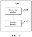
- a terminal device includes: a receiving module, configured to receive first control information sent by a network device, where the first control information is used to indicate configuration information used by the terminal device to perform data transmission or used to indicate bandwidth part BWP switching information used by the terminal device to perform BWP switching; a processing module, configured to: when the first control information is used to indicate the configuration information, perform data transmission based on the configuration information, where the processing module is further configured to: when the first control information is used to indicate the BWP switching information, perform BWP switching based on the BWP switching information.
- the first control information is used to indicate configuration information used by the terminal device to perform data transmission or used to indicate BWP switching information used by the terminal device to perform BWP switching includes: the first control information includes K bits, the first control information corresponds to one type of status information in 2 K states corresponding to the K bits, and K is a positive integer, where X pieces of status information in the 2 K types of status information are used to indicate the configuration information, Y pieces of status information in the 2 K types of status information are used to indicate the BWP switching information, the X pieces of status information are all different from the Y pieces of status information, X and Y are positive integers, and X+Y ⁇ 2 K .
- the first control information includes the K bits.
- the first control information may correspond to the 2 K types of status information.
- the X types of status information may be used to indicate the configuration information
- the Y types of status information may be used to indicate frequency band switching information.
- first X types of status information may be used to indicate the configuration information
- Y types of status information that follow the X states may be used to indicate the frequency band switching information.
- the first control information may indicate the configuration information or the frequency band switching information by using specific status information of the first control information.
- the first control information includes two bits.
- the first control information may correspond to four types of status information, for example, 00, 01, 10, and 11.
- the first two types of status information (00 and 01) may be used to indicate the configuration information used by the terminal device to perform data transmission.
- the latter two types of status information (10 and 11) are different from the states (00 and 01) indicating the configuration information
- it may be determined that 10 and 11 are used to indicate the frequency band switching information for example, indicate the terminal device to switch from a frequency band on which the terminal device is currently located to another frequency band.
- the first control information indicates the configuration information or the frequency band switching information by using different status information of the first control information.
- the terminal device may obtain the configuration information or frequency band switching indication information without reading a plurality of DCI formats, and does not need to continuously detect control information in timing duration to determine whether to perform frequency band switching. Therefore, power consumption of the terminal device and a latency in performing frequency band switching are reduced.
- the Y pieces of status information in the first control information are used to indicate first BWP switching information
- the first BWP switching information is used to indicate the terminal device to switch from a first BWP to a second BWP, and the second BWP is different from the first BWP
- the X pieces of status information in the first control information are used to indicate first configuration information
- the first configuration information is used by the terminal device to perform data transmission in the first BWP.
- the terminal device may obtain the configuration information or frequency band switching indication information without reading a plurality of DCI formats, and does not need to continuously detect control information in timing duration to determine whether to perform frequency band switching. Therefore, power consumption of the terminal device and a latency in performing frequency band switching are reduced.
- Y 1 pieces of status information in the Y pieces of status information are further used to indicate second configuration information
- the second configuration information is used by the terminal device to perform data transmission in the second BWP
- Y 1 is a positive integer
- the 2 K types of status information of the first control information may further include the Y 1 pieces of status information used to indicate both the frequency band switching information and the configuration information that is on a second frequency band after the terminal device switches to the second frequency band.
- the terminal device reads only one DCI format, and can receive the configuration information or the frequency band switching information on a current frequency band and switching information on a frequency band on which the terminal device is located after switching. This reduces power consumption of the terminal device and a latency in performing frequency band switching.
- Y 2 pieces of status information in the Y pieces of status information are further used to indicate the first configuration information, and Y 2 is a positive integer.
- the 2 K pieces of status information of the first control information may further include the Y 2 pieces of status information used to indicate both the first configuration information and the frequency band switching information.
- the terminal device may obtain, by using the first control information, configuration information and frequency band switching information on a frequency band on which the terminal device is currently located without reading a plurality of DCI formats, and does not need to continuously detect control information in timing duration to determine whether to perform frequency band switching. This reduces power consumption of the terminal device and a latency in performing frequency band switching.
- Y 3 pieces of status information in the Y pieces of status information are further used to indicate second BWP switching information
- the second BWP switching information is used to indicate the terminal device to switch from the second BWP to the first BWP
- Y 3 is a positive integer
- the 2 K pieces of status information of the first control information may further include the Y 3 pieces of status information used to indicate the second BWP switching information other than the configuration information and the frequency band switching information.
- the terminal device may then switch from the second frequency band to the first frequency band without continuously detecting control information in timing duration to determine whether to perform frequency band switching. This reduces power consumption of the terminal device and a latency in performing frequency band switching.
- a bandwidth of the first BWP is a minimum bandwidth needed for obtaining downlink data in a process in which the terminal device accesses the network device; or a bandwidth of the first BWP is a minimum bandwidth needed for a process in which the terminal device performs data transmission with the network device.
- the first BWP is a corresponding BWP in which the terminal device receives necessary system information sent by the network device; the first BWP is a BWP corresponding to a data channel or a control channel used when the terminal device receives necessary system information sent by the network device; or the bandwidth of the first BWP is less than or equal to a bandwidth of at least one second BWP, and both the first BWP and the at least one second BWP are BWPs configured by the network device for the terminal device.
- the configuration information is corresponding frequency resource allocation information.
- the status information used to indicate BWP switching and/or the second configuration information may reuse redundancy status information of fallback (Fall Back) DCI. That is, in addition to the frequency band switching information or the second configuration information that is used to indicate basic configuration information and that is provided in this embodiment of this application, no bit or status information needs to be newly added to the first control information.
- a network device includes: a processing module, configured to determine first control information, where the first control information is used to indicate configuration information used by a terminal device to perform data transmission or used to indicate BWP switching information used by the terminal device to perform BWP switching; and a sending module, configured to send the first control information to the terminal device.
- the first control information includes the K bits.
- possible states of the first control information include the 2 K types of status information.
- the X types of status information may be used to indicate the configuration information
- the Y types of status information may be used to indicate frequency band switching information.
- first X types of status information may be used to indicate the configuration information
- Y types of status information that follow the X states may be used to indicate the frequency band switching information.
- the first control information may indicate the configuration information or the frequency band switching information by using specific status information of the first control information.
- the first control information includes two bits.
- the first control information may include four states, for example, 00, 01, 10, and 11.
- 00 and 01 may be used to indicate the configuration information used by the terminal device to perform data transmission.
- 10 and 11 are different from the states (00 and 01) indicating the configuration information, it may be determined that 10 and 11 are used to indicate the frequency band switching information, for example, indicate the terminal device to switch from a frequency band on which the terminal device is currently located to another frequency band.
- the first control information indicates the configuration information or the frequency band switching information by using different status information of the first control information.
- the terminal device may obtain the configuration information or frequency band switching indication information without reading a plurality of DCI formats, and does not need to continuously detect control information in timing duration to determine whether to perform frequency band switching. Therefore, power consumption of the terminal device and a latency in performing frequency band switching are reduced.
- the Y pieces of status information in the first control information are used to indicate first BWP switching information
- the first BWP switching information is used to indicate the terminal device to switch from a first BWP to a second BWP, and the first BWP is different from the second BWP
- the X pieces of status information in the first control information are used to indicate first configuration information
- the first configuration information is used by the terminal device to perform data transmission in the first BWP.
- the terminal device may obtain the configuration information or frequency band switching indication information without reading a plurality of DCI formats, and does not need to continuously detect control information in timing duration to determine whether to perform frequency band switching. Therefore, power consumption of the terminal device and a latency in performing frequency band switching are reduced.
- Y 1 pieces of status information in the Y pieces of status information are further used to indicate second configuration information
- the second configuration information is used by the terminal device to perform data transmission in the second BWP
- Y 1 is a positive integer
- the 2 K types of status information of the first control information may further include the Y 1 pieces of status information used to indicate both the frequency band switching information and the configuration information that is on a second frequency band after the terminal device switches to the second frequency band.
- the terminal device reads only one DCI format, and can receive the configuration information or the frequency band switching information on a current frequency band and switching information on a frequency band on which the terminal device is located after switching. This reduces power consumption of the terminal device and a latency in performing frequency band switching.
- Y 2 pieces of status information in the Y pieces of status information are further used to indicate the first configuration information, and Y 2 is a positive integer.
- the 2 K types of status information of the first control information may further include the Y 2 pieces of status information used to indicate both the first configuration information and the frequency band switching information.
- the terminal device may obtain, by using the first control information, configuration information and frequency band switching information on a frequency band on which the terminal device is currently located without reading a plurality of DCI formats, and does not need to continuously detect control information in timing duration to determine whether to perform frequency band switching. This reduces power consumption of the terminal device and a latency in performing frequency band switching.
- Y 3 pieces of status information in the Y pieces of status information are further used to indicate second BWP switching information
- the second BWP switching information is used to indicate the terminal device to switch from the second BWP to the first BWP
- Y 3 is a positive integer
- the 2 K types of status information of the first control information may further include the Y 3 pieces of status information used to indicate the second BWP switching information other than the configuration information and the frequency band switching information.
- the terminal device may then switch from the second frequency band to the first frequency band without continuously detecting control information in timing duration to determine whether to perform frequency band switching. This reduces power consumption of the terminal device and a latency in performing frequency band switching.
- a bandwidth of the first BWP is a minimum bandwidth needed for obtaining downlink data in a process in which the terminal device accesses the network device; or a bandwidth of the first BWP is a minimum bandwidth needed for a process in which the terminal device performs data transmission with the network device.
- the first BWP is a corresponding BWP in which the terminal device receives necessary system information sent by the network device; the first BWP is a BWP corresponding to a data channel or a control channel used when the terminal device receives necessary system information sent by the network device; or the bandwidth of the first BWP is less than or equal to a bandwidth of at least one second BWP, and both the first BWP and the at least one second BWP are BWPs configured by the network device for the terminal device.
- the configuration information is corresponding frequency resource allocation information.
- the status information used to indicate BWP switching and/or the second configuration information may reuse redundancy status information of fallback (Fall Back) DCI. That is, in addition to the frequency band switching information or the second configuration information that is used to indicate basic configuration information and that is provided in this embodiment of this application, no bit or status information needs to be newly added to the first control information.
- a computer program storage medium includes program instructions.
- the program instructions are directly or indirectly executed, a terminal device or a network device is enabled to implement a function of the method according to any implementation of the first aspect or the second aspect.
- a chip system includes at least one processor.
- program instructions are executed in the at least one processor, a terminal device or a network device is enabled to implement a function of the method according to any implementation of the first aspect or the second aspect.
- a communication system includes a terminal device and a network device, the terminal device is configured to perform the method according to any implementation of the first aspect, and the network device is configured to perform the method according to any implementation of the second aspect.
- the terminal device by receiving the first control information that is sent by the network device and that can be used to indicate the configuration information or the BWP switching information, the terminal device may obtain the configuration information or the BWP switching information by detecting only the first control information. This avoids a problem of high power consumption caused by the terminal device detecting DCI in a plurality of formats or keeping enabling detection in timing duration.
- GSM global system for mobile communications
- CDMA code division multiple access
- WCDMA wideband code division multiple access
- GPRS general packet radio service
- LTE FDD frequency division duplex
- time division duplex time division duplex
- UMTS universal mobile telecommunications system
- WiMAX worldwide interoperability for microwave access
- 5G future 5th generation
- 5NR new radio
- a method provided in the embodiments may be further applied to a communication system, for example, a vehicle to everything (vehicle to everything, V2X) communication system, a long term evolution-vehicle (long term evolution vehicle, LTE-V) communication system, a vehicle to vehicle (vehicle to vehicle, V2V) communication system, a manual toll collection system (manual toll collection system, MTC), an internet of things (Internet of things, IoT) communication system, an LTE-machine to machine (LTE-machine to machine, LTE-M) communication system, and a machine to machine (M2M) communication system.
- V2X vehicle to everything
- LTE-V long term evolution vehicle
- LTE-V vehicle to vehicle
- V2V vehicle to vehicle
- MTC manual toll collection system
- IoT internet of things
- LTE-machine to machine LTE-machine to machine
- LTE-M machine to machine
- User equipment in the embodiments of this application may be a terminal device, an access terminal, a subscriber unit, a subscriber station, a mobile station, a remote station, a remote terminal, a mobile device, a user terminal, a terminal, a wireless communication device, a user agent, or a user apparatus.
- the terminal device may alternatively be a cellular phone, a cordless phone, a session initiation protocol (session initiation protocol, SIP) phone, a wireless local loop (wireless local loop, WLL) station, a personal digital assistant (personal digital assistant, PDA), a handheld device having a wireless communication function, a computing device or another processing device connected to a wireless modem, a vehicle-mounted device, a wearable device, a terminal device in a future 5G network or a terminal device in a future evolved public land mobile network (public land mobile network, PLMN), or the like. This is not limited in the embodiments of this application.
- a base station may be a base transceiver station (base transceiver station, BTS) in GSM or CDMA, may be a NodeB (nodeB, NB) in WCDMA, or may be an evolved NodeB (evolutional node B, eNodeB) in LTE, a base station gNB in 5G, or another network device having a function of a base station. This is not limited in this application.
- the user equipment, a relay device, or a network device includes a hardware layer, an operating system layer running on the hardware layer, and an application layer running on the operating system layer.
- the hardware layer includes hardware such as a central processing unit (central processing unit, CPU), a memory management unit (memory management unit, MMU), and a memory (which is also referred to as a main memory).
- the operating system may be any one or more computer operating systems that implement service processing through a process (process), for example, a Linux operating system, a Unix operating system, an Android operating system, an iOS operating system, or a Windows operating system.
- the application layer includes applications such as a browser, an address book, word processing software, and instant messaging software.
- a specific structure of an execution body of a method provided in the embodiments of this application is not particularly limited in the embodiments of this application, provided that a program that records code of the method provided in the embodiments of this application can be run to perform communication according to the method provided in the embodiments of this application.
- the execution body of the method provided in the embodiments of this application may be the terminal device or the network device, or a functional module that can invoke and execute the program in the terminal device or the network device.
- each BWP includes resource blocks (resource blocks, RBs) that are consecutive in frequency, and one RB includes 12 subcarriers (subcarriers).
- a network device may configure a maximum of four BWPs for the terminal device. If an initial BWP is included, the terminal device may have a maximum of five BWPs.
- the initial BWP may be considered as a BWP configured by the network device through a physical broadcast channel (physical broadcast channel, PBCH).
- PBCH physical broadcast channel
- a range of a frequency resource corresponding to a control resource set 0 (control resource set 0, CORESET 0) configured by the network device through the PBCH may correspond to a range of a frequency resource of the BWP.
- BWP switching may be implemented in the following manners. For ease of description, the following uses an example in which data transmission between the network device and the terminal device is performed through switching from a BWP A to a BWP B for description.
- the scheduling DCI includes indication information of a BWP
- the scheduling DCI sent by the network device in the BWP A may include indication information of the BWP B.
- the terminal device After receiving the information, the terminal device performs data transmission with the network device in the BWP B, to complete BWP switching.
- the scheduling DCI may be implemented by using a DCI format 0_1 or a DCI format 1_1, and is sent through a physical downlink control channel (physical downlink control channel, PDCCH).
- the terminal device may need to detect two DCI formats, and quantities of control information bits included in the two DCI formats are different, or sizes corresponding to the two DCI formats are different.
- the quantity of control information bits included in one DCI format is fixed, and the quantity of control information bits included in the other DCI format is variable, for example, may vary with information preconfigured by the network device.
- one DCI format includes control information bits related to a quantity of BWPs. When the quantity of BWPs configured by the network device for the terminal device is 2 or 4, the control information bits related to the quantity of BWPs may be 1 or 2.
- a DCI format including a fixed quantity of control information bits is referred to as fallback DCI (fall back DCI, FB DCI), and a DCI format including a variable quantity of control information bits is referred to as a non-fallback DCI (non-fall back DCI, non-FB DCI).
- the scheduling DCI for implementing BWP switching includes information related to BWP switching, and therefore may be understood as one type of non-FB DCI.
- the terminal device detects the FB DCI.
- the network device needs to send the non-FB DCI to the terminal device. That is, when BWP switching is implemented by using the DCI, the terminal device needs to simultaneously detect the DCI in two formats, and a quantity of detection times increases, thereby increasing power consumption of the terminal device.
- the terminal device may start a timer (timer). If no control information is detected in the BWP A in timing duration, the terminal device may switch to the BWP B.
- the BWP B may be understood as an initial BWP or a default BWP (default BWP), and the default BWP may be configured by the network device.
- the terminal device still needs to determine, by continuously detecting the control information within the timer, whether to switch to the BWP B. Because the terminal device needs to continuously detect the control information, power consumption of detecting the control information by the terminal device increases.
- Frequency band switching information is indicated by reusing a redundancy state of control information. That is, the control information may indicate configuration information, or may indicate control information for BWP switching.
- the terminal device can perform information configuration or BWP switching by receiving one type of DCI, and the terminal device does not need to detect DCI in two formats and continuously detect the control information in timing duration. This reduces power consumption of the terminal device and increase standby time of the terminal device.
- FIG. 1 is a schematic diagram of an applicable scenario of a data transmission method according to an embodiment of this application.
- the data transmission method provided in this embodiment of this application may be applied to wireless communication systems, including a 4.5G or 5G wireless communication system, a further-evolved system based on LTE or NR, and a future wireless communication system.
- the method may be further applied to a wireless communication system including a terminal device having a low bandwidth capability.
- a network device and a terminal device may be connected over an air interface.
- the terminal device used in the data transmission method provided in this embodiment of this application may include a device that provides a user with voice and/or data connectivity, for example, include a handheld device having a wireless connection function or a processing device connected to a wireless modem.
- the terminal device may be a terminal device supporting LTE communication, a terminal device supporting 5G communication, user equipment, or the like.
- a relay device (relay) and any other device that can perform data communication with the network device may be included in the terminal device described in this embodiment of this application.
- the network device used in the data transmission method provided in this embodiment of this application may include an access network (access network, AN) device, for example, may be a device that is in an access network and that communicates with a wireless terminal device over an air interface through one or more cells.
- the network device is a base station, and the base station includes an LTE eNB, a home evolved NodeB (home evolve NodeB, HeNB), a relay device, a femto cell (femto), a pico cell (pico), a 5G base station, or the like.
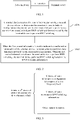
- FIG. 2 is a schematic flowchart of a data transmission method according to an embodiment of this application.
- the data transmission method may include the following steps.
- a terminal device receives first control information sent by a network device, where the first control information is used to indicate configuration information used by the terminal device to perform data transmission or used to indicate BWP switching information used by the terminal device to perform BWP switching.
- a frequency band on which data transmission between the terminal device and the network device is currently performed a frequency band determined by the terminal device in a process of accessing the network device, or an active frequency band is referred to as a first BWP.
- the frequency band determined by the terminal device in the process of accessing the network device may be, for example, a frequency band on which the terminal device performs data transmission in an idle state (idle state) or in an inactive state (inactive state).
- the data transmission includes data receiving, data sending, or other information transmission.
- At least one other BWP that is configured by the network device for the terminal device and in which data transmission can be performed may be a second BWP.
- the first BWP may be a minimum bandwidth that is of a frequency resource and that is needed for performing uplink data transmission or downlink data transmission between the network device and the terminal device, so that power consumption can be reduced in a data transmission process between the network device and the terminal device.
- a type of the first BWP is not limited in this embodiment, and the type described above is merely one possible type.
- the first BWP may be a BWP in an NR system, for example, an initial BWP.
- the first BWP is a BWP corresponding to a minimum downlink bandwidth needed by the terminal device to access the network device.
- the initial BWP in the NR system may be a corresponding BWP in which the network device sends a necessary system information block type 1 (system information block type1, SIB1), a BWP corresponding to a control channel used by the network device to send the SIB 1, or a BWP corresponding to a data channel used by the network device to send the SIB 1.
- system information block type1, SIB1 system information block type1
- SIB1 system information block type 1
- the first BWP may include a plurality of consecutive frequency resource units, and one frequency resource unit may be, for example, a resource block (resource block, RB).
- resource block resource block
- the configuration information may include a plurality of types.
- the configuration information in the BWP may include at least one of the following: a frequency position of the first BWP, the bandwidth of the first BWP, a numerology (numerology) used by the terminal device to perform data transmission with the network device in the first BWP, configuration information related to a PDCCH transmitted in the first BWP, and configuration information related to a physical uplink control channel (physical uplink control channel, PUCCH) transmitted in the first BWP.
- the frequency position of the first BWP may be represented by a center frequency position of the first BWP, or represented by a start frequency position and/or an end frequency position of the first BWP.
- the frequency position of the first BWP may alternatively be represented in a plurality of manners. This is not limited in this application.
- the numerology may include a subcarrier spacing (subcarrier spacing, SCS) and/or a quantity of symbols included in a slot.
- the configuration information corresponding to the PDCCH may include at least one of the following: a range of a frequency resource for PDCCH transmission, a PDCCH candidate set, and an aggregation level (aggregation level, AL) corresponding to the PDCCH.
- the PDCCH candidate set may be represented by a search space (search space, SS) corresponding to the PDCCH.
- the aggregation level of the PDCCH may be understood as a size of a frequency resource used for transmission of one PDCCH, and may generally be represented by a quantity of minimum resource units needed for transmission of a control channel. For example, if a minimum resource unit needed for transmission of one PDCCH is represented by a control channel element (control channel element, CCE), the frequency resource for transmission of one PDCCH may be one CCE, two CCEs, four CCEs, eight CCEs, 16 CCEs, and the like.
- the aggregation level AL may be 1, 2, 4, 8, or 16.
- the configuration information corresponding to the PUCCH may include at least one of the following: PUCCH format information and an uplink control information bit (bit) carried on the PUCCH.
- the downlink control channel is a channel used to carry downlink control information.
- the downlink control channel in this embodiment of this application may be an sPDCCH, an NR-PDCCH, or another channel that is newly defined in a future communication protocol and whose function is similar to the downlink control channel.
- the sPDCCH short PDCCH or shortened PDCCH
- the NR-PDCCH new radio PDCCH
- a type and a name of the downlink control channel are not limited in this embodiment of this application, and all downlink control channels are collectively referred to as PDCCHs.
- the aggregation level is also referred to as an aggregation level, and may represent a quantity of consecutive CCEs occupied by one PDCCH. That is, one downlink control channel is obtained through aggregation of L downlink control channel elements (control channel elements, CCEs), where L is a positive integer.
- the aggregation level of the PDCCH is L, and specifically a value of L may be 1, 2, 4, or 8. It should be noted that, to improve reliability of the PDCCH, the value of L may alternatively be 16 or 32.
- One CCE may include n REGs, where n is a positive integer.
- n is a positive integer.
- a value of n may be 3, 4, or 6.
- the search space is a set of candidate downlink control channels, and may be understood as a set that is obtained by combining one or more candidate downlink control channels. Each candidate downlink control channel can be used to carry downlink control information.
- the terminal device needs to monitor a candidate downlink control channel. Therefore, the search space is a set of candidate downlink control channels that the terminal device monitors.
- Control resource set (control-resource set, CORESET):
- the control resource set is a resource set used for transmission of downlink control information, and may also be referred to as a control resource area or a PDCCH resource set.
- the terminal device may receive the first control information sent by the network device in a plurality of manners, for example, information received on a physical broadcast channel (physical broadcast channel, PBCH), information received by using radio resource control (radio resource control, RRC) signaling, information received by using media access control (medium access control, MAC) signaling, or information received on a PDCCH or a physical downlink shared channel (physical downlink shared channel, PDSCH).
- PBCH physical broadcast channel
- RRC radio resource control
- MAC media access control
- PDCCH physical downlink shared channel
- PDSCH physical downlink shared channel
- the configuration information and frequency band switching indication information may be sent by the network device to the terminal device by using a first information field in the first control information, or it may be understood that a first information field is used to indicate the configuration information and/or frequency band switching.
- the first information field may be a field including a part of bits in one piece of DCI.
- the first control information may carry the configuration information or the BWP switching information of the terminal device in the first BWP.
- the first control information sent each time has only one state.
- status information presented by the first control information may be status information of the configuration information.
- the first control information cannot include BWP switching indication information.
- the configuration information and the BWP switching information may be specifically represented in the first control information in a plurality of manners. The following describes the configuration information and the BWP switching information in the first control information with reference to the accompanying drawings.
- the terminal device When the first control information is used to indicate the configuration information, the terminal device performs data transmission based on the configuration information. When the first control information indicates the terminal device to perform BWP switching, the terminal device performs BWP switching based on the BWP switching information.
- the configuration information that is related to the first BWP and that is configured by the network device for the terminal device is recorded as first configuration information
- the configuration information related to the second BWP is recorded as second configuration information
- the first configuration information may include at least one of the following: the frequency position of the first BWP, the bandwidth of the first BWP, the numerology used by the terminal device to perform data transmission with the network device in the first BWP, the configuration information related to the PDCCH for performing data transmission in the first BWP, the configuration information related to the PUCCH transmitted in the first BWP, and control information associated with data transmission, for example, scheduling information associated with data transmission.
- the scheduling information associated with data transmission may include at least one of the following: control information indicating a frequency resource used for data transmission, control information indicating a time domain resource for data transmission, control information indicating a modulation scheme, control information indicating a transport block size (transmission block size, TBS), and control information indicating a redundancy version (redundancy version, RV) corresponding to data transmission.
- control information indicating a frequency resource used for data transmission may include at least one of the following: control information indicating a frequency resource used for data transmission, control information indicating a time domain resource for data transmission, control information indicating a modulation scheme, control information indicating a transport block size (transmission block size, TBS), and control information indicating a redundancy version (redundancy version, RV) corresponding to data transmission.
- TBS transmission block size
- RV redundancy version
- the first control information may indicate the terminal device to perform BWP switching. Specifically, the first control information may indicate the terminal device to switch from a first BWP in which the terminal device is currently located or an active first BWP to the second BWP, or after the terminal device switches from the first BWP to the second BWP, the first control information may further indicate the terminal device to switch back from the second BWP to the first BWP. It may be understood that the first BWP in which the terminal device is currently located may be understood as a corresponding frequency band on which current data transmission between the terminal device and the network device is performed.
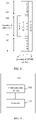
- FIG. 3 is a schematic diagram of a representation manner of configuration information and BWP switching information in first control information according to an embodiment of this application.
- the first control information may indicate the configuration information or the BWP switching information.
- the first control information may correspond to 2 K states in a binary system.
- X states in the 2 K states corresponding to the first control information may represent first configuration information.
- a 0 th state to an (X-1) th state may be used to represent the first configuration information.
- the first configuration information may be configuration information of a first BWP in which a terminal device accesses a network device or performs data transmission with the network device.
- Y states in the 2 K states corresponding to the first control information may be used to indicate the terminal device to perform BWP switching. That is, when a state of the first control information is any one of the Y states, the terminal device may switch from the first BWP in which the terminal device is currently located to a second BWP based on BWP switching indicated by the first control information.
- bandwidths of the first BWP and the second BWP are different; or a position of a frequency band resource corresponding to the first BWP is different from a position of a frequency band resource corresponding to the second BWP, and the frequency band resource corresponding to the first BWP partially overlaps the frequency band resource corresponding to the second BWP, or does not overlap the frequency band resource corresponding to the second BWP at all.
- the bandwidths of the first BWP and the second BWP may both be a bandwidth A, and the bandwidth A is a minimum bandwidth needed when the terminal device performs data transmission with the network device.
- the data transmission performed between the terminal device and the network device includes data transmission in a process in which the terminal device accesses the network device, and data transmission performed after the terminal device establishes a connection to the network device.
- the data transmission in the process in which the terminal device accesses the network device may be understood as data transmission between the terminal device and the network device in a process in which the terminal device enters an inactive state from an idle state, or data transmission between the terminal device and the network device in a process in which the terminal device enters a connected state from an idle state.
- the X states are all different from the Y states, that is, any one of the X states is different from any one of the Y states.
- both X and Y are integers greater than or equal to 0, and X+Y may be equal to 2 K , or X+Y may be less than 2 K . This is not limited in this application.
- first BWP switching information is used to indicate the terminal device to switch from the first BWP to the second BWP.
- the Y states of the first control information may further include second configuration information, the first configuration information, or second BWP switching information, the second configuration information is configuration information of the terminal device in the second BWP, and the second BWP switching information is used to indicate the terminal device to switch from the second BWP to the first BWP.
- the Y states may be considered as a set, the set may be divided into a plurality of subsets, the plurality of subsets respectively include Y 1 states, Y 2 states, Y 2 states, and the like, and Y 1 +Y 2 +Y 3 ⁇ Y.
- the Y 1 states in the Y states may be further used to indicate the second configuration information.
- the Y states may be further specifically divided into: The X th state to the (X+Y 1 -1) th state may be used to indicate the first BWP switching information and the second configuration information.
- the Y 2 states in the Y states may be used to indicate both the first BWP switching information and the first configuration information.
- an (X+Y 1 ) th state to an (X+Y 1 +Y 2 -1) th state may be used to indicate the first BWP switching information and the first configuration information.
- a value range corresponding to the Y 2 states in the 2 K states is (X+Y 1 ) to (X+Y 1 +Y 2 -1).
- the Y 3 states in the Y states may be used to indicate the first BWP switching information, the second configuration information, and the second BWP switching information.
- an (X+Y 1 +Y 2 ) th state to an (X+Y 1 +Y 2 +Y 3 -1) th state may be used to indicate the first BWP switching information, the second configuration information, and the second BWP switching information.
- a value range corresponding to the Y 3 states is (X+Y 1 +Y 2 ) to (X+Y 1 +Y 2 +Y 3 -1). It may be understood that the value ranges of the foregoing states in the 2 K states are merely examples.
- the configuration information and the frequency band switching information included in the first control information may be another combination other than the foregoing enumerated combinations. This is not limited in this application.
- 2 K types of status information of the first control information may correspond to different numbers, for example, 0 to (2 K -1). Each number corresponds to different status information.
- a quantity of pieces of status information whose number value range is within a first range may be X, and the X pieces of status information are used to indicate the first configuration information; and a quantity of pieces of status information whose number value range is within a second range may be Y, and the Y pieces of status information are used to indicate the first BWP switching information or used to indicate the first BWP switching information and other information.
- each type of status information in the Y pieces of status information corresponds to the first BWP switching information; each type of status information in the Y pieces of status information corresponds to the first BWP switching information and other information; or in the Y pieces of status information, some status information corresponds to the first BWP switching information, and some status information corresponds to the first BWP switching information and other information.
- Table 1 Number range of status information Quantity of pieces of corresponding status information Specific meaning First value range X First configuration information Second value range Y First BWP switching information, or first BWP switching information and other information
- the Y pieces of status information may further indicate other information.
- the other information herein may be the second configuration information, the first configuration information, the second BWP switching information, or any combination of the foregoing three types of information.
- 2 K types of status information of the first control information may correspond to different numbers, for example, 0 to (2 K -1). Each number corresponds to different status information.
- a quantity of pieces of status information whose number value range is within a first range may be X, and the X pieces of status information are used to indicate the first configuration information; and a quantity of pieces of status information whose number value range is within a second range may be Y 1 , and the Y 1 pieces of status information are used to indicate the first BWP switching information and the second configuration information.
- the second value range described in Table 2 may be different from the second value range described in Table 1.
- the second value range corresponding to numbers of the Y 1 pieces of status information in Table 2 is a subset of a value range corresponding to numbers of the Y pieces of status information. That is, the Y pieces of status information may further include other status information except the Y 1 pieces of status information, and numbers of the other status information may be a third value range.
- Table 2 Number range of status information Corresponding status information Specific meaning First value range X pieces of status information First configuration information Second value range Y 1 pieces of status information First BWP switching information and second configuration information Third value range In the Y pieces of status information, other status information except the Y 1 pieces of status information First BWP switching information, or first BWP switching information and other information
- the Y pieces of status information may further indicate other information.
- the other information herein may be the second configuration information, the first configuration information, the second BWP switching information, or any combination of the foregoing three types of information.
- 2 K types of status information of the first control information may correspond to different numbers, for example, 0 to (2 K -1). Each number corresponds to different status information.
- a quantity of pieces of status information whose number value range is within a first range may be X, and the X pieces of status information are used to indicate the first configuration information
- a quantity of pieces of status information whose number value range is within a second range may be Y 1 , and the Y 1 pieces of status information are used to indicate the first BWP switching information and the second configuration information
- a quantity of pieces of status information whose number value range is within a third value range may be Y2, and the Y2 pieces of status information are used to indicate the first BWP switching information and the first configuration information.
- the third value range described in Table 3 may be different from the third value range described in Table 2.
- the third value range described in Table 3 may be a subset of the third value range described in Table 2.
- fourth value ranges in the following Table 4 and Table 3 may be different.
- both the second value range and the third value range in Table 3 are subsets of a value range corresponding to numbers of the Y pieces of status information. That is, the Y pieces of status information may further include other status information except the Y 1 pieces of status information and the Y 2 pieces of status information, and numbers of the other status information may be a fourth value range.
- Table 3 Number range of status information Corresponding status information Specific meaning First value range X pieces of status information First configuration information Second value range Y 1 pieces of status information First BWP switching information and second configuration information Third value range Y 2 pieces of status information First BWP switching information and first configuration information Fourth value range In the Y pieces of status information, other status information except the Y 1 pieces of status information and the Y 2 pieces of status information First BWP switching information, or first BWP switching information and other information
- the Y pieces of status information may further indicate other information.
- the other information herein may be the second configuration information, the first configuration information, the second BWP switching information, or any combination of the foregoing three types of information.
- 2 K types of status information of the first control information may correspond to different numbers, for example, 0 to (2 K -1). Each number corresponds to different status information.
- a quantity of pieces of status information whose number value range is within a first range may be X, and the X pieces of status information are used to indicate the first configuration information
- a quantity of pieces of status information whose number value range is within a second range may be Y 1 , and the Y 1 pieces of status information are used to indicate the first BWP switching information and the second configuration information
- a quantity of pieces of status information whose number value range is within a third value range may be Y 2
- the Y 2 pieces of status information are used to indicate the first BWP switching information and the first configuration information
- a quantity of pieces of status information whose number value range is within a fourth value range may be Y 3 , and the Y 3 pieces of status information are used to indicate the first BWP switching information and the second BWP switching information.
- the fourth value range described in Table 4 may be different from the fourth value range described in Table 3.
- the second value range, the third value range, and the fourth value range in Table 4 are all subsets of a value range corresponding to numbers of the Y pieces of status information. That is, the Y pieces of status information may further include other status information except the Y 1 pieces of status information, the Y 2 pieces of status information, and the Y 3 pieces of status information, and numbers of the other status information may be a fifth value range.
- Table 4 Number range of status information Corresponding status information Specific meaning First value range X pieces of status information First configuration information Second value range Y 1 pieces of status information First BWP switching information and second configuration information Third value range Y 2 pieces of status information First BWP switching information and first configuration information Fourth value range Y 3 pieces of status information First BWP switching information and second BWP switching information Fifth value range In the Y pieces of status information, other status information except the Y 1 pieces of status information, the Y 2 pieces of status information, and the Y 3 pieces of status information First BWP switching information, or first BWP switching information and other information
- the Y pieces of status information may further indicate other information.
- the other information herein may be the second configuration information, the first configuration information, the second BWP switching information, or any combination of the foregoing three types of information.
- the 2 K states of the first control information may include the X states used to indicate the first configuration information and the Y states used to indicate the first BWP switching.
- the Y states may further specifically include one or more of the second configuration information, the first configuration information, and the second BWP switching information.
- all of the Y states are used to indicate the first BWP switching; or some of the Y states are used to indicate the first BWP switching, and some of the Y states are used to indicate one or more of the first BWP switching, the second configuration information, the first configuration information, and the second BWP switching information. It may be understood that switching performed by the terminal device from the first BWP to different second BWPs may correspond to different states.
- the terminal device may further receive the second configuration information sent by the network device, and the second configuration information is configuration information related to the second BWP.
- the second configuration information may include at least one of the following: a frequency position of the second BWP, a bandwidth of the second BWP, a numerology used by the terminal device to perform data transmission with the network device in the second BWP, configuration information related to a PDCCH for performing data transmission in the second BWP, configuration information related to a PUCCH transmitted in the second BWP, and control information associated with data transmission, for example, scheduling information associated with data transmission.
- the scheduling information associated with data transmission may include at least one of the following: control information indicating a frequency resource used for data transmission, control information indicating a time domain resource for data transmission, control information indicating a modulation scheme, control information indicating a transport block size, and control information indicating a redundancy version corresponding to data transmission. It may be understood that the first configuration information may alternatively be control information included on a downlink control channel for scheduling data transmission.
- the frequency position of the second BWP may be represented by a center frequency position of the second BWP, or represented by a start frequency position and/or an end frequency position of the second BWP.
- the frequency position of the second BWP may alternatively be represented in a plurality of manners. This is not limited in this application.
- the numerology may include an SCS.
- the configuration information corresponding to the PDCCH may include at least one of the following: a range of a frequency resource for PDCCH transmission, a PDCCH candidate set, and an AL corresponding to the PDCCH.
- the PDCCH candidate set may be represented by an SS corresponding to the PDCCH.
- the aggregation level of the PDCCH may be understood as a size of a frequency resource used for transmission of one PDCCH, and may generally be represented by a quantity of minimum resource units needed for transmission of a control channel. For example, if a minimum resource unit needed for transmission of one PDCCH is represented by a CCE, the frequency resource for transmission of one PDCCH may be one CCE, two CCEs, four CCEs, eight CCEs, 16 CCEs, and the like.
- the aggregation level AL may be 1, 2, 4, 8, or 16.
- the configuration information corresponding to the PUCCH may include at least one of the following: PUCCH format information and an uplink control information bit carried on the PUCCH.
- the terminal device may obtain the first configuration information and the second configuration information through a same physical transmission channel or by using same signaling.
- both the first configuration information and the second configuration information are carried in same RRC signaling.
- various states that may be indicated by the first control information may be implemented through joint coding, and the first control information cannot simultaneously indicate a plurality of states.
- the first control information cannot simultaneously indicate the first configuration information represented by the X states, and the first BWP switching information and the second configuration information that are represented by the Y states.
- the network device may send a plurality of pieces of first control information to the terminal device, and specific states of the plurality of pieces of first control information may be different, to indicate the terminal to perform different operations.
- the first control information may be used to indicate the configuration information or the BWP switching information, and the terminal device may obtain the configuration information or the BWP switching information by detecting only the first control information. This avoids a problem of high power consumption and a high latency in performing frequency band switching that are caused by the terminal device detecting DCI in a plurality of formats or keeping enabling detection in timing duration.
- FIG. 4 is a schematic diagram of another representation manner of configuration information and BWP switching information in first control information according to an embodiment of this application.
- the first control information may indicate first configuration information or indicate the BWP switching information and the second configuration information.
- the first control information may correspond to 2 K states in a binary system.
- X states in the 2 K states corresponding to the first control information may represent the first configuration information
- the first configuration information may be configuration information of a first BWP in which a terminal device accesses a network device or performs data transmission with the network device.
- Y states in the 2 K states corresponding to the first control information may be used to indicate first BWP switching information for the terminal device to perform BWP switching
- Y 1 pieces of status information in the Y 1 pieces of status information may be used to indicate both the first BWP switching information and the second configuration information.
- the terminal device may switch from the first BWP in which the terminal device is currently located to a second BWP based on the BWP switching information indicated by the first control information, and perform data transmission in the second BWP based on the second configuration information.
- bandwidths of the first BWP and the second BWP are different; or a position of a frequency band resource corresponding to the first BWP is different from a position of a frequency band resource corresponding to the second BWP, and the frequency band resource corresponding to the first BWP partially overlaps the frequency band resource corresponding to the second BWP, or does not overlap the frequency band resource corresponding to the second BWP at all.
- the bandwidths of the first BWP and the second BWP may both be a bandwidth A, and the bandwidth A is a minimum bandwidth needed when the terminal device performs data transmission with the network device.
- the data transmission performed between the terminal device and the network device includes data transmission in a process in which the terminal device accesses the network device, and data transmission performed after the terminal device establishes a connection to the network device.
- the data transmission in the process in which the terminal device accesses the network device may be understood as data transmission between the terminal device and the network device in a process in which the terminal device enters an inactive state from an idle state, or data transmission between the terminal device and the network device in a process in which the terminal device enters a connected state from an idle state.
- Y 1 is a positive integer less than Y.
- the foregoing Y pieces of status information may further include other status information.
- the other status information may further indicate the first configuration information, second BWP switching information, a combination thereof, and the like.
- an information type indicated by the other status information needs to be different from an information type indicated by the Y 1 pieces of status information.
- the Y 1 pieces of status information are used to indicate both the first BWP switching information and the second configuration information, and in this case, the other status information does not include status information used to indicate both the first BWP switching information and the second configuration information.
- the status information used to indicate both the first BWP switching information and the second configuration information has been completely included in the Y 1 pieces of status information.
- the second configuration information is information associated with the data transmission in the second BWP after the terminal device performs switching.
- the terminal device may determine, based on the first control information, that a corresponding state is one of the Y 1 pieces of status information, switch from the current first BWP to the second BWP based on the first BWP switching information indicated by the status information, and further perform, based on the second configuration information, data transmission with the network device in the second BWP that is switched to.
- the X states are all different from the Y states, that is, any one of the X states is different from any one of the Y states.
- both X and Y are integers greater than or equal to 0, and X+Y may be equal to 2 K , or X+Y may be less than 2 K . This is not limited in this application.
- the terminal device may further receive the second configuration information sent by the network device, and the second configuration information is configuration information related to the second BWP.
- An information type included in the second configuration information or a manner in which the terminal device obtains the second configuration information is similar to that of the first configuration information. To avoid repetition, details are not described herein again.
- the terminal device may obtain the first configuration information and the second configuration information through a same physical transmission channel or by using same signaling.
- both the first configuration information and the second configuration information are carried in same RRC signaling.
- first control information may be implemented through joint coding, and each piece of first control information sent by the network device to the terminal device cannot simultaneously indicate a plurality of states.
- the first control information cannot simultaneously indicate the first configuration information represented by the X states, and the first BWP switching information and the second configuration information that are represented by the Y states.
- the first control information can indicate only one state at a time.
- the state may indicate the configuration information or the BWP switching information of the terminal device in the first BWP based on different requirements.
- the network device may send a plurality of pieces of first control information to the terminal device, and specific states of the plurality of pieces of first control information may be different, to indicate the terminal to perform different operations.
- bandwidths of the first BWP and the second BWP may be minimum bandwidths that are of frequency resources and that are needed when the network device performs uplink data transmission or downlink data transmission with the terminal device, so that power consumption can be reduced in a data transmission process between the network device and the terminal device.
- the first BWP may be a BWP in an NR system, for example, an initial BWP.
- the first BWP is a BWP corresponding to a minimum downlink bandwidth needed by the terminal device to access the network device.
- the initial BWP in the NR system may be a corresponding BWP in which the network device sends a necessary SIB 1, a BWP corresponding to a control channel used by the network device to send the SIB 1, or a BWP corresponding to a data channel used by the network device to send the SIB 1.
- the bandwidth of the first BWP is described in detail below.
- the first BWP may include a plurality of consecutive frequency resource units, and one frequency resource unit may be, for example, an RB.
- the configuration information may include a plurality of types.
- the configuration information in the BWP may include at least one of the following: a frequency position of the first BWP, the bandwidth of the first BWP, a numerology used by the terminal device to perform data transmission with the network device in the first BWP, configuration information related to a PDCCH for performing data transmission in the first BWP, and configuration information related to a PUCCH transmitted in the first BWP.
- the frequency position of the first BWP may be represented by a center frequency position of the first BWP, or represented by a start frequency position and/or an end frequency position of the first BWP.
- the frequency position of the first BWP may alternatively be represented in a plurality of manners. This is not limited in this application.
- the numerology may include an SCS.
- the configuration information corresponding to the PDCCH may include at least one of the following: a range of a frequency resource for PDCCH transmission, a PDCCH candidate set, and an AL corresponding to the PDCCH.
- the PDCCH candidate set may be represented by an SS corresponding to the PDCCH.
- the aggregation level of the PDCCH may be understood as a size of a frequency resource used for transmission of one PDCCH, and may generally be represented by a quantity of minimum resource units needed for transmission of a control channel. For example, if a minimum resource unit needed for transmission of one PDCCH is represented by a CCE, the frequency resource for transmission of one PDCCH may be one CCE, two CCEs, four CCEs, eight CCEs, 16 CCEs, and the like.
- the aggregation level AL may be 1, 2, 4, 8, or 16.
- the configuration information corresponding to the PUCCH may include at least one of the following: PUCCH format information and an uplink control information bit carried on the PUCCH.
- the terminal device may receive the first control information sent by the network device in a plurality of manners, for example, information carried on a PBCH, information received by using RRC signaling, information received by using MAC signaling, or information received on a PDCCH or a PDSCH.
- a manner in which the terminal device receives the first control information sent by the network device is not limited in this embodiment of this application.
- the configuration information and frequency band switching indication information may be sent by the network device to the terminal device by using a first information field in the first control information, or it may be understood that a first information field is used to indicate the configuration information and/or frequency band switching.
- the first information field may be a field including a part of bits in one piece of DCI.
- the first control information may carry the configuration information or the BWP switching information of the terminal device in the first BWP, and the configuration information and the BWP switching information may not be simultaneously carried or represented by the first control information.
- the first control information sent each time has only one state.
- status information presented by the first control information may be status information of the configuration information. In this case, the first control information cannot include BWP switching indication information.
- the first control information may be used to indicate the configuration information or the BWP switching information, and the terminal device may obtain the configuration information or the BWP switching information by detecting only the first control information. This avoids a problem of high power consumption and a high latency in performing frequency band switching that are caused by the terminal device detecting DCI in a plurality of formats or keeping enabling detection in timing duration.
- FIG. 5 is a schematic diagram of still another representation manner of configuration information and BWP switching information in first control information according to an embodiment of this application.
- the first control information may indicate the configuration information or indicate the BWP switching information and first configuration information.
- the first control information may correspond to 2 K states in a binary system.
- X states in the 2 K states corresponding to the first control information may represent the first configuration information
- the first configuration information may be configuration information of a first BWP in which a terminal device accesses a network device or performs data transmission with the network device.
- Y states in the 2 K states corresponding to the first control information may be used to indicate the first BWP for the terminal device to perform BWP switching.
- the Y pieces of status information may further specifically include Y 2 pieces of status information, and the Y 2 pieces of status information are used to indicate both the first BWP configuration information and the first configuration information.
- the terminal device may perform data transmission with the network device on a first frequency band based on the first configuration information indicated by the first control information, and then switch, based on the first BWP switching information, from the first BWP in which the terminal device is currently located to a second BWP.
- bandwidths of the first BWP and the second BWP are different; or a position of a frequency band resource corresponding to the first BWP is different from a position of a frequency band resource corresponding to the second BWP, and the frequency band resource corresponding to the first BWP partially overlaps the frequency band resource corresponding to the second BWP, or does not overlap the frequency band resource corresponding to the second BWP at all.
- both the first BWP and the second BWP are minimum bandwidths that satisfy a bandwidth requirement in a process in which the terminal device accesses the network device or performs data transmission with the network device.
- the bandwidths of the first BWP and the second BWP may both be a bandwidth A, and the bandwidth A is a minimum bandwidth needed when the terminal device performs data transmission with the network device.
- the data transmission performed between the terminal device and the network device includes data transmission in a process in which the terminal device accesses the network device, and data transmission performed after the terminal device establishes a connection to the network device.
- the data transmission in the process in which the terminal device accesses the network device may be understood as data transmission between the terminal device and the network device in a process in which the terminal device enters an inactive state from an idle state, or data transmission between the terminal device and the network device in a process in which the terminal device enters a connected state from an idle state.
- Y 2 is a positive integer less than or equal to Y.
- the foregoing Y pieces of status information may further include other status information.
- the other status information may further indicate the first configuration information, the second BWP switching information, a combination thereof, and the like.
- an information type indicated by the other status information needs to be not completely the same as an information type indicated by the Y 2 pieces of status information.
- the Y 2 pieces of status information are used to indicate both the first BWP switching information and the first configuration information, and in this case, the other status information no longer includes status information used to indicate both the first BWP switching information and the first configuration information.
- the status information used to indicate both the first BWP switching information and the first configuration information has been completely included in the Y 2 pieces of status information.
- the X states are all different from the Y states, that is, any one of the X states is different from any one of the Y states.
- both X and Y are integers greater than or equal to 0, and X+Y may be equal to 2 K , or X+Y may be less than 2 K . This is not limited in this application.
- the first control information may indicate the first configuration information by using one of the X states of the first control information.
- the first control information may indicate the BWP switching information and the first configuration information by using one of the Y states of the first control information.
- the terminal device may perform information configuration based on the first configuration information in the first control information, and access the network device or perform data transmission with the network device.
- the terminal device may perform information configuration related to the first BWP based on the first configuration information in the first control information to perform data transmission with the network device, and switch from the first BWP to the second BWP based on the BWP switching information.
- the terminal device may further receive the second configuration information sent by the network device, and the second configuration information is configuration information related to the second BWP.
- An information type included in the second configuration information or a manner in which the terminal device obtains the second configuration information is similar to that of the first configuration information. To avoid repetition, details are not described herein again.
- the first BWP may be a minimum bandwidth that is of a frequency resource and that is needed for performing uplink data transmission or downlink data transmission between the network device and the terminal device, so that power consumption can be reduced in a data transmission process between the network device and the terminal device.
- the first BWP may be a BWP in an NR system, for example, an initial BWP.
- the first BWP is a BWP corresponding to a minimum downlink bandwidth needed by the terminal device to access the network device.
- the initial BWP in the NR system may be a corresponding BWP in which the network device sends a necessary SIB 1, a BWP corresponding to a control channel used by the network device to send the SIB 1, or a BWP corresponding to a data channel used by the network device to send the SIB 1.
- the bandwidth of the first BWP is described in detail below.
- the first BWP may include a plurality of consecutive frequency resource units, and one frequency resource unit may be, for example, an RB.
- the configuration information may include a plurality of types.
- the configuration information in the BWP may include at least one of the following: a frequency position of the first BWP, the bandwidth of the first BWP, a numerology used by the terminal device to perform data transmission with the network device in the first BWP, configuration information related to a PDCCH for performing data transmission in the first BWP, and configuration information related to a PUCCH transmitted in the first BWP.
- the frequency position of the first BWP may be represented by a center frequency position of the first BWP, or represented by a start frequency position and/or an end frequency position of the first BWP.
- the frequency position of the first BWP may alternatively be represented in a plurality of manners. This is not limited in this application.
- the numerology may include an SCS.
- the configuration information corresponding to the PDCCH may include at least one of the following: a range of a frequency resource for PDCCH transmission, a PDCCH candidate set, and an AL corresponding to the PDCCH.
- the PDCCH candidate set may be represented by an SS corresponding to the PDCCH.
- the aggregation level of the PDCCH may be understood as a size of a frequency resource used for transmission of one PDCCH, and may generally be represented by a quantity of minimum resource units needed for transmission of a control channel. For example, if a minimum resource unit needed for transmission of one PDCCH is represented by a CCE, the frequency resource for transmission of one PDCCH may be one CCE, two CCEs, four CCEs, eight CCEs, 16 CCEs, and the like.
- the aggregation level AL may be 1, 2, 4, 8, or 16.
- the configuration information corresponding to the PUCCH may include at least one of the following: PUCCH format information and an uplink control information bit carried on the PUCCH.
- the terminal device may receive the first control information sent by the network device in a plurality of manners, for example, information carried on a PBCH, information received by using RRC signaling, information received by using MAC signaling, or information received on a PDCCH or a PDSCH.
- a manner in which the terminal device receives the first control information sent by the network device is not limited in this embodiment of this application.
- the terminal device may obtain the first configuration information and the second configuration information through a same physical transmission channel or by using same signaling.
- both the first configuration information and the second configuration information are carried in same RRC signaling.
- first control information may be considered to be implemented through joint coding, and each piece of first control information sent by the network device to the terminal device cannot simultaneously indicate a plurality of states.
- the first control information cannot simultaneously indicate the first configuration information represented by the X states, and the first BWP switching information and the second configuration information that are represented by the Y states.
- the first control information can indicate only one state at a time.
- the state may indicate the configuration information or the BWP switching information of the terminal device in the first BWP based on different requirements.
- the network device may send a plurality of pieces of first control information to the terminal device, and specific states of the plurality of pieces of first control information may be different, to indicate the terminal to perform different operations.
- the first control information may be used to indicate the configuration information or indicate both the BWP switching information and the configuration information, and the terminal device may obtain the configuration information or obtain both the BWP switching information and the configuration information by detecting only the first control information. This avoids a problem of high power consumption caused by the terminal device detecting DCI in a plurality of formats or keeping enabling detection in timing duration.
- FIG. 6 is a schematic diagram of still another representation manner of configuration information and BWP switching information in first control information according to an embodiment of this application.
- the first control information may indicate the configuration information or indicate the BWP switching information and second configuration information.
- the first control information may correspond to 2 K states in a binary system.
- X states in the 2 K states of the first control information may be used to indicate first configuration information
- the first configuration information may be configuration information in a first BWP when a terminal device accesses a network device or performs data transmission with the network device.
- Y states in the 2 K states corresponding to the first control information may be used to indicate first BWP switching information
- the Y pieces of status information may specifically include Y 3 pieces of status information.
- the Y 3 pieces of status information are used to simultaneously indicate the first BWP switching information, the second configuration information, and second BWP switching information.
- the first BWP switching information is used to indicate the terminal device to switch from a current first BWP to a second BWP.
- Second BWP indication information may be used to indicate the terminal device to switch back from the second BWP to the first BWP or switch from the second BWP to another BWP after switching to the second BWP.
- the terminal device may switch from the first BWP in which the terminal device is currently located to the second BWP based on the first BWP switching information indicated by the first control information, switch back from the second BWP to the first BWP based on the second BWP switching information indicated by the first control information, or perform data transmission with the network device in the second BWP based on the second configuration information indicated by the first control information.
- Bandwidths of the first BWP and the second BWP are different, and both the first BWP and the second BWP are minimum bandwidths that satisfy a bandwidth requirement in a process in which the terminal device accesses the network device or performs data transmission with the network device.
- Y 3 is a positive integer less than or equal to Y.
- the foregoing Y pieces of status information may further include other status information.
- the other status information may further indicate the first configuration information, the second BWP switching information, the second configuration information, a combination thereof, and the like. It may be further understood that in the Y states, an information type indicated by the other status information needs to be not completely the same as an information type indicated by the Y 3 pieces of status information.
- the Y 3 pieces of status information are used to simultaneously indicate the first BWP switching information, the second BWP switching information, and the second configuration information, and in this case, the other status information no longer includes status information used to simultaneously indicate the first BWP switching information, the second BWP switching information, and the second configuration information.
- the status information used to indicate both the first BWP switching information and the first configuration information has been completely included in the Y 3 pieces of status information.
- the X states are all different from the Y states, that is, any one of the X states is different from any one of the Y states.
- both X and Y are integers greater than or equal to 0, and X+Y may be equal to 2 K , or X+Y may be less than 2 K . This is not limited in this application.
- the first control information may indicate the first configuration information by using one of the X states of the first control information.
- the first control information may indicate the BWP switching information and the second configuration information by using one of the Y states of the first control information.
- the terminal device may perform information configuration based on the first configuration information in the first control information, and access the network device or perform data transmission with the network device.
- the terminal device may perform information configuration related to the second BWP based on the second configuration information in the first control information to perform data transmission with the network device.
- the first BWP and the second BWP may be minimum bandwidths that are of frequency resources and that are needed for performing uplink data transmission or downlink data transmission between the network device and the terminal device, so that power consumption can be reduced in a data transmission process between the network device and the terminal device.
- the first BWP may be a BWP in an NR system, for example, an initial BWP.
- the first BWP is a BWP corresponding to a minimum downlink bandwidth needed by the terminal device to access the network device.
- the initial BWP in the NR system may be a corresponding BWP in which the network device sends a necessary SIB 1, a BWP corresponding to a control channel used by the network device to send the SIB 1, or a BWP corresponding to a data channel used by the network device to send the SIB 1.
- the bandwidth of the first BWP is described in detail below.
- the first BWP may include a plurality of consecutive frequency resource units, and one frequency resource unit may be, for example, an RB.
- the configuration information may include a plurality of types.
- the configuration information in the BWP may include at least one of the following: a frequency position of the first BWP, the bandwidth of the first BWP, a numerology used by the terminal device to perform data transmission with the network device in the first BWP, configuration information related to a PDCCH for performing data transmission in the first BWP, and configuration information related to a PUCCH transmitted in the first BWP.
- the frequency position of the first BWP may be represented by a center frequency position of the first BWP, or represented by a start frequency position and/or an end frequency position of the first BWP.
- the frequency position of the first BWP may alternatively be represented in a plurality of manners. This is not limited in this application.
- the numerology may include an SCS.
- the configuration information corresponding to the PDCCH may include at least one of the following: a range of a frequency resource for PDCCH transmission, a PDCCH candidate set, and an AL corresponding to the PDCCH.
- the PDCCH candidate set may be represented by an SS corresponding to the PDCCH.
- the aggregation level of the PDCCH may be understood as a size of a frequency resource used for transmission of one PDCCH, and may generally be represented by a quantity of minimum resource units needed for transmission of a control channel. For example, if a minimum resource unit needed for transmission of one PDCCH is represented by a CCE, the frequency resource for transmission of one PDCCH may be one CCE, two CCEs, four CCEs, eight CCEs, 16 CCEs, and the like.
- the aggregation level AL may be 1, 2, 4, 8, or 16.
- the configuration information corresponding to the PUCCH may include at least one of the following: PUCCH format information and an uplink control information bit carried on the PUCCH.
- the terminal device may receive the first control information sent by the network device in a plurality of manners, for example, information carried on a PBCH, information received by using RRC signaling, information received by using MAC signaling, or information received on a PDCCH or a PDSCH.
- a manner in which the terminal device receives the first control information sent by the network device is not limited in this embodiment of this application.
- various states that may be indicated by the first control information may be considered to be implemented through joint coding, and the first control information cannot simultaneously indicate a plurality of states.
- the first control information cannot simultaneously indicate the first configuration information represented by the X states, and the first BWP switching information and the second configuration information that are represented by the Y states.
- the first control information can indicate only one state at a time.
- the state may indicate the configuration information or the BWP switching information of the terminal device in the first BWP based on different requirements.
- the network device may send a plurality of pieces of first control information to the terminal device, and specific states of the plurality of pieces of first control information may be different, to indicate the terminal to perform different operations.
- the first control information may be used to indicate the configuration information or indicate both the BWP switching information and the configuration information, and the terminal device may obtain the configuration information or obtain both the BWP switching information and the configuration information by detecting only the first control information. This avoids a problem of high power consumption caused by the terminal device detecting DCI in a plurality of formats or keeping enabling detection in timing duration.
- FIG. 7 is a schematic diagram of still another representation manner of configuration information and BWP switching information in first control information according to an embodiment of this application.
- the first control information provided in this embodiment of this application includes X pieces of status information and Y pieces of status information.
- the X pieces of status information are used to indicate first configuration information, that is, a terminal device may perform data transmission with a network device in a first BWP based on the first configuration information.
- the Y pieces of status information are used to indicate first BWP switching information, that is, the terminal device may switch from the first BWP to a second BWP based on any one of the Y pieces of status information.
- the Y pieces of status information may be further divided more specifically.
- the Y pieces of status information may further include Y 1 pieces of status information used to simultaneously indicate the first BWP switching and Y 3 pieces of status information used to simultaneously indicate the first BWP switching information, second BWP switching information, and second configuration information.
- Y 1 +Y 3 is less than or equal to Y.
- various states that may be indicated by the first control information may be implemented through joint coding, and the first control information cannot simultaneously indicate a plurality of states.
- the first control information cannot simultaneously indicate the first configuration information represented by the X states, and the first BWP switching information and the second configuration information that are represented by the Y states.
- the first control information can indicate only one state at a time.
- the state may indicate the configuration information or the BWP switching information of the terminal device in the first BWP based on different requirements.
- the network device may send a plurality of pieces of first control information to the terminal device, and specific states of the plurality of pieces of first control information may be different, to indicate the terminal to perform different operations.
- the terminal device may determine, based on the first control information, that a corresponding state is one of the Y 3 states, then first switch from the first BWP in which the terminal device is currently located to the second BWP based on an indication of the state, and then, in the second BWP, perform data transmission with the network device in the second BWP based on one of detected N states (the second configuration information). In an implementation, after ensuring correct data transmission, the terminal device switches back from the second BWP to the first BWP based on one of the N states.
- the first control information provided in this embodiment of this application may be control information included in FB DCI, for example, control information included in a DCI format 0_0 or a DCI format 1_0.
- the control information included in the DCI format 0_0 or the DCI format 1_0 may be further understood as that transmission of the control information is performed by using the DCI format 0_0 or the DCI format 1_0.
- the Y states included in the first control information may reuse redundancy status information of the FB DCI.
- Y 1 , Y 2 , and Y 3 that are specifically included in the Y states and that are enumerated in this embodiment of this application are merely examples and are not exhaustive.
- the Y states may further include a plurality of other types of configuration information or BWP band switching information, and combinations thereof. This is not limited in this application.
- the correct data transmission in this embodiment of this application may include: If the terminal device sends uplink data to the network device, the terminal device can determine that the uplink data is correctly received only after receiving an acknowledgement (acknowledgement, ACK) corresponding to the uplink data sent by the network device. Alternatively, if the terminal device receives downlink data sent by the network device, the network device can determine that the downlink data is correctly received only after receiving an ACK sent by the terminal device for the downlink data. It may be understood that, in this embodiment of this application, after the terminal device sends the uplink data to the network device, all data that is sent by the network device and that can enable the terminal device to confirm that the network device correctly receives the uplink data may be considered as an ACK. On the other hand, after the network device sends the downlink data, all data that is sent by the terminal device and that can enable the network device to confirm that the terminal device correctly receives the downlink data may be considered as an ACK.
- time in which the terminal device switches back from the second BWP to the first BWP may be set by default. For example, after the terminal device completes data transmission with the network device in the second BWP based on one of the Y 3 states, the terminal device may switch back to the first BWP. Alternatively, time in which the terminal device switches back from the second BWP to the first BWP may be indicated by a state in the first control information. This is not limited in this application.
- the time of switching back from the second BWP to the first BWP may alternatively be indicated by the first control information.
- the first control information may also indicate specific time in which the terminal device switches back from the second BWP to the first BWP.
- the terminal device does not need to detect control information of the terminal device within a timer, then switches to another BWP after the timer ends, and may determine duration for performing data transmission with the network device in the second BWP only by using a control state in the first control information, to avoid that the terminal device always detects the control information within the timer (even if the network device does not schedule control information to be sent to the terminal device within the timer). This reduces power consumption consumed by the terminal device for completing BWP switching, thereby achieving an objective of power saving.
- the terminal device may simultaneously implement data transmission and/or BWP switching by using the first control information in the first BWP. Therefore, DCI formats in two formats do not need to be simultaneously detected as that in a conventional technology. Further, a process of BWP switching performed by the terminal device is simplified, implementation complexity of BWP switching performed by the terminal device is reduced, and power consumption consumed by the terminal device for completing BWP switching is reduced, thereby achieving the objective of power saving.
- the terminal does not need to detect two or more DCI formats, but implements information configuration or BWP switching by using the first control information in one DCI format.
- the first control information is frequency domain resource allocation information
- a maximum bandwidth of the terminal device is 5 MHz, and if an SCS used when the terminal device performs data transmission is 15 kHz, a maximum quantity of RBs that may be used simultaneously for data transmission between the terminal device and the network device is 25.
- Downlink data transmission is used as an example.
- a resource allocation manner of the downlink data transmission between the terminal device and the network device is a resource allocation manner of consecutive frequency domains per RB, according to a current protocol and based on a maximum quantity of RBs that can be used, it may be determined that a quantity of bits used to indicate frequency domain resource allocation information is 9.
- the first control information may further indicate first BWP switching.
- the first BWP switching may alternatively be represented as the first BWP switching information
- second BWP switching may alternatively be represented as the second BWP switching information.
- Table 5 State of the first control information Second BWP index (index) after switching 111111111 0 111111110 1 111111101 2 111111100 3
- the first control information includes K bits, and the first control information corresponds to one type of status information in 2 K states. It is assumed that X is not greater than (2 K -1) and Y is not greater than (2 K -1), whether the first control information indicates one type of status information in the X states or one type of status information in the Y states may be distinguished by using a value of a most significant bit (bit) of the K bits.
- the first control information indicates one type of status information in the X states; on the other hand, if bits corresponding to the first control information are 1xxxxxxxx, the first control information indicates one type of status information in the Y states, where x represents one bit, and a value of the bit is 0 or 1.
- the terminal device in the first BWP, to further reduce power consumption of the terminal device, the terminal device may be limited to detect only an FB DCI format in the first BWP for terminal device-specific scheduling information, and does not need to detect a non-FB DCI format.
- the terminal device may determine the scheduling information and the BWP switching information by detecting DCI in only one format. Therefore, the terminal device is limited to detecting only the FB DCI format in the first BWP. This not only reduces complexity of detecting DCI by the terminal device, thereby reducing power consumption of the terminal device, but also ensures implementation of data scheduling and BWP switching functions.
- the terminal device may be limited to detect only non-FB DCI in the second BWP for terminal device-specific scheduling information, and a quantity of pieces of DCI detected by the terminal device is limited. This can reduce power consumption of the terminal device.
- transmission parameters corresponding to physical downlink channels used for transmission of the first control information may be limited. This reduces power consumption of the terminal device for detecting the first control information.
- the corresponding transmission parameters herein include a quantity of configured CORESETs, a quantity of search spaces, a quantity of blind detection times, an aggregation level, and the like.
- the physical downlink channels herein include a PDCCH and a PDSCH.
- the first BWP, the second BWP, and the like in this embodiment of this application may be a minimum bandwidth that can be used to implement data transmission in a process in which the terminal device accesses the network device or the terminal device performs data transmission with the network device.
- the possible bandwidth of the first BWP is described in more detail with reference to the accompanying drawings.
- the bandwidth of the first BWP in which the terminal device is located may be equal to a minimum downlink bandwidth needed for the terminal device to access the network device.
- An NR system is used as an example.
- a minimum downlink bandwidth needed for accessing a network may be understood as an additional transmission bandwidth corresponding to a downlink signal or downlink information and a necessary guard bandwidth that need to be obtained by the terminal device for accessing the NR system.
- a minimum downlink bandwidth needed for accessing the network device may be only downlink information or a downlink signal that needs to be obtained by the terminal device for accessing the NR system, and does not include a necessary guard bandwidth.
- To access the NR system at least the following downlink information or downlink signal need to be obtained.
- Synchronization signal block (synchronization signal block, SSB)
- the SSB includes a primary synchronization signal (primary synchronization signal, PSS), a secondary synchronization signal (secondary synchronization signal, SSS), and a PBCH.
- the SSB occupies four orthogonal frequency division multiplexing (orthogonal frequency division multiplexing, OFDM) symbols in time. Transmission of the PSS and the SSS is separately performed on the first OFDM symbol and the third OFDM symbol. Corresponding transmission bandwidths are 12 resource blocks (resource blocks, RBs) (more precisely, the transmission bandwidths of the PSS and the SSS correspond to 127 subcarriers).
- Transmission of information included in the PBCH is performed on the second symbol, the third symbol, and the fourth symbol, where on the second OFDM symbol and the fourth OFDM symbol, a transmission bandwidth is 20 RBs (corresponding to 240 subcarriers), and on the third OFDM symbol, a transmission bandwidth is eight RBs (corresponding to 96 subcarriers).
- a transmission bandwidth corresponding to an SSB is 20 RBs, and one RB includes 12 subcarriers. Therefore, transmission bandwidths corresponding to an SSB are different based on different subcarrier spacings SCSs.
- Table 6 shows transmission bandwidths corresponding to an SSB at several different subcarrier spacings. Table 6 SCS/kHz 15 30 120 240 SSB transmission bandwidth/MHz 3.6 7.2 28.8 57.6
- the necessary SI in the data transmission method provided in this embodiment of this application may be understood as minimum system information that the terminal device needs to obtain before initiating random access to the network device.
- the terminal device may determine, by using control information on the PBCH, control information for scheduling a SIB 1, and then determine the SIB 1 by using the control information for scheduling the SIB 1 (which is SIB 1 control information for short below).
- the SIB 1 includes necessary information, for example, a random access preamble (preamble), needed by the terminal device to initiate random access to the terminal device.
- the necessary system information in this embodiment of this application may be represented by the SIB 1.
- the terminal device may separately receive the SSB and the SIB 1 at different moments, a maximum value between a transmission bandwidth corresponding to the SSB and a transmission bandwidth corresponding to the SIB 1 may be used as a minimum bandwidth available for accessing the NR system. Further, if the terminal device obtains the SIB 1, the terminal device needs to first read the SIB 1 control information, and then determine the SIB 1 based on the SIB 1 control information.
- the transmission bandwidth corresponding to the SIB 1 may be represented by a transmission bandwidth corresponding to the SIB 1 control information or the transmission bandwidth corresponding to the SIB 1.
- the SIB 1 control information is carried on the PDCCH
- the SIB 1 is carried on the PDSCH.
- the transmission bandwidth corresponding to the SIB 1 may be represented by a transmission bandwidth corresponding to the PDCCH carrying the SIB 1 control information or a transmission bandwidth corresponding to the PDSCH carrying the SIB 1.
- a maximum value between a minimum transmission bandwidth corresponding to the SIB 1 and the transmission bandwidth corresponding to the SSB may be used as the minimum bandwidth available for accessing the NR system.
- the transmission bandwidth corresponding to the SIB 1 control information may be 24 RBs, 48 RBs, or 96 RBs.
- 24 RBs (4.32 MHz) may be used as the minimum transmission bandwidth corresponding to the SIB 1.
- the minimum bandwidth needed for accessing the NR system can be understood as 4.32 MHz.
- the transmission bandwidth corresponding to the SIB 1 control information may be 48 RBs, or may be 96 RBs.
- 48 RBs (8.64 MHz) may be used as the minimum transmission bandwidth corresponding to the SIB 1.
- the transmission bandwidth corresponding to the SSB is 20 RBs (7.2 MHz)
- the minimum bandwidth available for accessing the NR system may be understood as 8.64 MHz.
- the SIB 1 control information may alternatively be carried on another physical layer channel, for example, an enhanced physical downlink control channel (enhanced physical downlink control channel, EPDCCH).
- the SIB 1 may alternatively be carried on another physical layer channel. This is not limited in this application.
- the first BWP may be, for example, an initial BWP in the current NR system.
- the initial BWP may be understood as a BWP corresponding to the SIB 1 sent by the network device.
- the initial BWP may be a BWP corresponding to a control channel used by the network device to send the SIB 1, or a BWP corresponding to a data channel used by the network device to send the SIB 1.
- the control channel used by the network device to send the SIB 1 may include a control channel of control information for scheduling the SIB 1, and the control channel may be, for example, a PDCCH.
- the terminal device may determine, by receiving the PBCH sent by the network device, a control channel configuration for scheduling the SIB 1, determine, based on control channel configuration information of the SIB 1, scheduling control information for scheduling the SIB 1, and determine the SIB 1 based on the scheduling control information. If a BWP corresponding to the control channel for scheduling the SIB 1 indicated by indication information included in the PBCH is represented by a CORESET #0, the initial BWP may be understood as the CORESET #0.
- a bandwidth of the first BWP may be less than a bandwidth of another BWP.
- the network device may further configure another BWP. Compared with the bandwidth of the another BWP, the bandwidth of the first BWP is at least not greater than the bandwidth of the another BWP. Specifically, the bandwidth of the first BWP may be less than the bandwidth of the another BWP.
- a smaller bandwidth indicates smaller power consumption of the terminal device. Therefore, when the first BWP is the initial BWP or the bandwidth of the first BWP is less than the bandwidth of the another BWP, complexity of detecting control information by the terminal device in the first BWP may be reduced, thereby reducing power consumption of the terminal device.
- PDCCH configuration information corresponding to the first BWP may also be limited.
- the PDCCH configuration information is as described above. By limiting the PDCCH configuration information, complexity of detecting control information by the terminal device may be further reduced, and power consumption may be reduced.
- the control information herein may be, for example, control information including the first control information described above.
- the first BWP may also be understood as an energy saving BWP.
- FIG. 9 is a schematic diagram of a structure of a terminal device according to an embodiment of this application.
- the terminal device 900 includes a communication interface 910 and a processor 920.
- the communication interface 910 may be configured to receive, in a first BWP, first control information sent by a network device, where the first control information is used to indicate configuration information used by the terminal device to perform data transmission or used to indicate bandwidth part BWP switching information used by the terminal device to perform BWP switching.
- the processor 920 may be configured to: when the first control information indicates the configuration information, perform data transmission based on the configuration information; or when the first control information indicates the BWP switching information, perform BWP switching based on the BWP switching information.
- that the first control information is used to indicate configuration information used by the terminal device to perform data transmission or used to indicate BWP switching information used by the terminal device to perform BWP switching includes: the first control information includes K bits, and the first control information corresponds to one type of status information in 2 K states corresponding to the K bits where X pieces of status information in the 2 K types of status information are used to indicate the configuration information, Y pieces of status information in the 2 K types of status information are used to indicate the BWP switching information, the X pieces of status information are all different from the Y pieces of status information, and X+Y ⁇ 2 K .
- the Y pieces of status information in the first control information are used to indicate first BWP switching information
- the first BWP switching information is used to indicate the terminal device to switch from a first BWP to a second BWP, and the second BWP is different from the first BWP
- the X pieces of status information in the first control information are used to indicate first configuration information
- the first configuration information is used by the terminal device to perform data transmission in the first BWP.
- Y 1 pieces of status information in the Y pieces of status information are further used to indicate second configuration information, and the second configuration information is used by the terminal device to perform data transmission in the second BWP.
- Y 2 pieces of status information in the Y pieces of status information are further used to indicate the first configuration information.
- the first control information further includes N states
- Y 3 pieces of status information in the Y pieces of status information are further used to indicate second BWP switching information
- the second BWP switching information is used to indicate the terminal device to switch from the second BWP to the first BWP.
- a bandwidth of the first BWP is a minimum bandwidth needed for obtaining downlink data in a process in which the terminal device accesses the network device; or a bandwidth of the first BWP is a minimum bandwidth needed for a process in which the terminal device performs data transmission with the network device.
- the first BWP is a corresponding BWP in which the terminal device receives necessary system information sent by the network device; the first BWP is a BWP corresponding to a data channel or a control channel used when the terminal device receives necessary system information sent by the network device; or the bandwidth of the first BWP is less than or equal to a bandwidth of at least one second BWP, and both the first BWP and the at least one second BWP are BWPs configured by the network device for the terminal device.
- the configuration information is corresponding frequency resource allocation information.
- FIG. 10 is a schematic diagram of a structure of a network device according to an embodiment of this application.
- the network device 1000 includes a processor 1010 and a communication interface 1020.
- the processor 1010 may be configured to determine first control information, where the first control information is used to indicate configuration information used by a terminal device to perform data transmission or used to indicate BWP switching information used by the terminal device to perform BWP switching.
- the communication interface 1020 may be configured to send the first control information to the terminal device.
- the first control information is used to indicate configuration information used by a terminal device to perform data transmission or used to indicate BWP switching information used by the terminal device to perform BWP switching includes: the first control information includes K bits, and the first control information corresponds to one type of status information in 2 K states corresponding to the K bits where X pieces of status information in the 2 K types of status information are used to indicate the configuration information, Y pieces of status information in the 2 K types of status information are used to indicate the BWP switching information, the X pieces of status information are all different from the Y pieces of status information, and X+Y ⁇ 2 K .
- the Y pieces of status information in the first control information are used to indicate first BWP switching information
- the first BWP switching information is used to indicate the terminal device to switch from a first BWP to a second BWP, and the second BWP is different from the first BWP
- the X pieces of status information in the first control information are used to indicate first configuration information
- the first configuration information is used by the terminal device to perform data transmission in the first BWP.
- Y 1 pieces of status information in the Y pieces of status information are further used to indicate second configuration information, and the second configuration information is used by the terminal device to perform data transmission in the second BWP.
- Y 2 pieces of status information in the Y pieces of status information are further used to indicate the first configuration information.
- the first control information further includes N states
- Y 3 pieces of status information in the Y pieces of status information are further used to indicate second BWP switching information
- the second BWP switching information is used to indicate the terminal device to switch from the second BWP to the first BWP.
- a bandwidth of the first BWP is a minimum bandwidth needed for obtaining downlink data in a process in which the terminal device accesses the network device; or a bandwidth of the first BWP is a minimum bandwidth needed for a process in which the terminal device performs data transmission with the network device.
- the first BWP is a corresponding BWP in which the terminal device receives necessary system information sent by the network device; the first BWP is a BWP corresponding to a data channel or a control channel used when the terminal device receives necessary system information sent by the network device; or the bandwidth of the first BWP is less than or equal to a bandwidth of at least one second BWP, and both the first BWP and the at least one second BWP are BWPs configured by the network device for the terminal device.
- the configuration information is corresponding frequency resource allocation information.
- FIG. 11 is a schematic diagram of a structure of a terminal device according to an embodiment of this application.
- the terminal device 1100 includes a receiving module 1101 and a processing module 1102.
- the receiving module 1102 may be configured to receive first control information sent by a network device, where the first control information is used to indicate configuration information used by the terminal device to perform data transmission or used to indicate bandwidth part BWP switching information used by the terminal device to perform BWP switching.
- the processing module 1102 may be configured to: when the first control information is used to indicate the configuration information, perform data transmission based on the configuration information.
- the processing module may be further configured to: when the first control information is used to indicate the BWP switching information, perform BWP switching based on the BWP switching information.
- that the first control information is used to indicate configuration information used by the terminal device to perform data transmission or used to indicate BWP switching information used by the terminal device to perform BWP switching includes: the first control information includes K bits, and the first control information corresponds to one type of status information in 2 K states corresponding to the K bits where X pieces of status information in the 2 K types of status information are used to indicate the configuration information, Y pieces of status information in the 2 K types of status information are used to indicate the BWP switching information, the X pieces of status information are all different from the Y pieces of status information, and X+Y ⁇ 2 K .
- the Y pieces of status information in the first control information are used to indicate first BWP switching information
- the first BWP switching information is used to indicate the terminal device to switch from a first BWP to a second BWP, and the second BWP is different from the first BWP
- the X pieces of status information in the first control information are used to indicate first configuration information
- the first configuration information is used by the terminal device to perform data transmission in the first BWP.
- Y 1 pieces of status information in the Y pieces of status information are further used to indicate second configuration information, and the second configuration information is used by the terminal device to perform data transmission in the second BWP.
- Y 2 pieces of status information in the Y pieces of status information are further used to indicate the first configuration information.
- the first control information further includes N states
- Y 3 pieces of status information in the Y pieces of status information are further used to indicate second BWP switching information
- the second BWP switching information is used to indicate the terminal device to switch from the second BWP to the first BWP.
- a bandwidth of the first BWP is a minimum bandwidth needed for obtaining downlink data in a process in which the terminal device accesses the network device; or a bandwidth of the first BWP is a minimum bandwidth needed for a process in which the terminal device performs data transmission with the network device.
- the first BWP is a corresponding BWP in which the terminal device receives necessary system information sent by the network device; the first BWP is a BWP corresponding to a data channel or a control channel used when the terminal device receives necessary system information sent by the network device; or the bandwidth of the first BWP is less than or equal to a bandwidth of at least one second BWP, and both the first BWP and the at least one second BWP are BWPs configured by the network device for the terminal device.
- the configuration information is corresponding frequency resource allocation information.
- FIG. 12 is a schematic diagram of a structure of a network device according to an embodiment of this application.
- the terminal device 1200 includes a processing module 1201 and a sending module 1202.
- the processing module 1201 may be configured to determine first control information, where the first control information is used to indicate configuration information used by a terminal device to perform data transmission or used to indicate BWP switching information used by the terminal device to perform BWP switching.
- the sending module 1202 may be configured to send the first control information to the terminal device.
- the first control information is used to indicate configuration information used by a terminal device to perform data transmission or used to indicate BWP switching information used by the terminal device to perform BWP switching includes: the first control information includes K bits, and the first control information corresponds to one type of status information in 2 K states corresponding to the K bits where X pieces of status information in the 2 K types of status information are used to indicate the configuration information, Y pieces of status information in the 2 K types of status information are used to indicate the BWP switching information, the X pieces of status information are all different from the Y pieces of status information, and X+Y ⁇ 2 K .
- the Y pieces of status information in the first control information are used to indicate first BWP switching information
- the first BWP switching information is used to indicate the terminal device to switch from a first BWP to a second BWP, and the second BWP is different from the first BWP
- the X pieces of status information in the first control information are used to indicate first configuration information
- the first configuration information is used by the terminal device to perform data transmission in the first BWP.
- Y 1 pieces of status information in the Y pieces of status information are further used to indicate second configuration information, and the second configuration information is used by the terminal device to perform data transmission in the second BWP.
- Y 2 pieces of status information in the Y pieces of status information are further used to indicate the first configuration information.
- the first control information further includes N states
- Y 3 pieces of status information in the Y pieces of status information are further used to indicate second BWP switching information
- the second BWP switching information is used to indicate the terminal device to switch from the second BWP to the first BWP.
- a bandwidth of the first BWP is a minimum bandwidth needed for obtaining downlink data in a process in which the terminal device accesses the network device; or a bandwidth of the first BWP is a minimum bandwidth needed for a process in which the terminal device performs data transmission with the network device.
- the first BWP is a corresponding BWP in which the terminal device receives necessary system information sent by the network device; the first BWP is a BWP corresponding to a data channel or a control channel used when the terminal device receives necessary system information sent by the network device; or the bandwidth of the first BWP is less than or equal to a bandwidth of at least one second BWP, and both the first BWP and the at least one second BWP are BWPs configured by the network device for the terminal device.
- the configuration information is corresponding frequency resource allocation information.
- terminal device and the network device shown in FIG. 11 and FIG. 12 may be configured to perform the method in any one of the foregoing embodiments.
- B corresponding to A indicates that B is associated with A, and B may be determined based on A.
- determining A based on B does not mean that B is determined based only on A. That is, B may also be determined based on A and/or other information.
- the disclosed system, apparatus, and method may be implemented in other manners.
- the described apparatus embodiment is merely an example.
- division into units is merely logical function division and may be other division in actual implementation.
- a plurality of units or components may be combined or integrated into another system, or some features may be ignored or not performed.
- the displayed or discussed mutual couplings or direct couplings or communication connections may be implemented through some interfaces.
- the indirect couplings or communication connections between the apparatuses or units may be implemented in electrical, mechanical, or other forms.
- the units described as separate parts may or may not be physically separate, and parts displayed as units may or may not be physical units, may be located in one position, or may be distributed on a plurality of network units. Some or all of the units may be selected based on actual requirements to achieve the objectives of the solutions of the embodiments.
- the functions When the functions are implemented in a form of a software functional unit and sold or used as an independent product, the functions may be stored in a computer-readable storage medium. Based on such an understanding, the technical solutions of this application essentially, or the part contributing to the prior art, or some of the technical solutions may be implemented in a form of a software product.
- the computer software product is stored in a storage medium, and includes several instructions for instructing a computer device (which may be a personal computer, a server, or a network device) to perform all or some of the steps of the methods described in the embodiments of this application.
- the foregoing storage medium includes: any medium that can store program code, such as a USB flash drive, a removable hard disk, a read-only memory (Read-Only Memory, ROM), a random access memory (random access memory, RAM), a magnetic disk, or an optical disc.
- program code such as a USB flash drive, a removable hard disk, a read-only memory (Read-Only Memory, ROM), a random access memory (random access memory, RAM), a magnetic disk, or an optical disc.
Landscapes
- Engineering & Computer Science (AREA)
- Signal Processing (AREA)
- Computer Networks & Wireless Communication (AREA)
- Mobile Radio Communication Systems (AREA)
Applications Claiming Priority (1)
| Application Number | Priority Date | Filing Date | Title |
|---|---|---|---|
| PCT/CN2019/101101 WO2021030962A1 (zh) | 2019-08-16 | 2019-08-16 | 数据传输的方法、终端设备及网络设备 |
Publications (2)
| Publication Number | Publication Date |
|---|---|
| EP4013148A1 true EP4013148A1 (de) | 2022-06-15 |
| EP4013148A4 EP4013148A4 (de) | 2022-07-20 |
Family
ID=74659841
Family Applications (1)
| Application Number | Title | Priority Date | Filing Date |
|---|---|---|---|
| EP19942226.2A Pending EP4013148A4 (de) | 2019-08-16 | 2019-08-16 | Verfahren zur datenübertragung, endgerätevorrichtung und netzwerkvorrichtung |
Country Status (4)
| Country | Link |
|---|---|
| US (1) | US20220167317A1 (de) |
| EP (1) | EP4013148A4 (de) |
| CN (1) | CN114175789B (de) |
| WO (1) | WO2021030962A1 (de) |
Families Citing this family (1)
| Publication number | Priority date | Publication date | Assignee | Title |
|---|---|---|---|---|
| US20250159612A1 (en) * | 2023-11-13 | 2025-05-15 | Qualcomm Incorporated | Wideband ue power saving by switching wideband data to narrowband data with wideband reference signal |
Family Cites Families (21)
| Publication number | Priority date | Publication date | Assignee | Title |
|---|---|---|---|---|
| KR102474512B1 (ko) * | 2016-02-12 | 2022-12-06 | 삼성전자 주식회사 | 이동통신 시스템에서 단말의 제어 정보 수신 방법 및 장치 |
| KR102383385B1 (ko) * | 2017-04-17 | 2022-04-08 | 삼성전자 주식회사 | 업링크 전력 제어를 위한 방법 및 장치 |
| CN109152050B (zh) * | 2017-06-15 | 2021-03-23 | 华为技术有限公司 | 下行控制信道参数的配置方法、网络设备和终端设备 |
| JP6777813B2 (ja) * | 2017-07-28 | 2020-10-28 | エルジー エレクトロニクス インコーポレイティド | 無線通信システムにおいてbwp動作を遂行する方法、及びこのための装置 |
| CN109474375B (zh) * | 2017-09-08 | 2021-10-22 | 维沃移动通信有限公司 | 一种资源调度方法、基站和终端 |
| CN109586881B (zh) * | 2017-09-29 | 2021-11-12 | 株式会社Kt | 用于在新无线电中切换带宽部分的方法和装置 |
| US10980007B2 (en) * | 2017-09-29 | 2021-04-13 | Samsung Electronics Co., Ltd | Uplink resource configuration method and apparatus in wireless communication system |
| EP3787189A1 (de) * | 2017-11-09 | 2021-03-03 | Comcast Cable Communications LLC | Csi-übertragung mit teilen mit mehreren bandbreiten |
| JP6910621B2 (ja) * | 2017-11-09 | 2021-07-28 | オフィノ, エルエルシー | 無線デバイスの機能に基づいた通信 |
| CN109788553A (zh) * | 2017-11-10 | 2019-05-21 | 华为技术有限公司 | 一种带宽切换方法及装置 |
| CN109788559B (zh) * | 2017-11-14 | 2021-01-08 | 维沃移动通信有限公司 | 非对称频谱的带宽部分bwp切换方法、终端及网络设备 |
| US20190222404A1 (en) * | 2018-01-12 | 2019-07-18 | Qualcomm Incorporated | Signaling techniques for bandwidth parts |
| CN110099447B (zh) * | 2018-01-31 | 2024-04-30 | 中兴通讯股份有限公司 | 一种信息传输方法及装置 |
| CN110121210B (zh) * | 2018-02-06 | 2023-08-01 | 大唐移动通信设备有限公司 | 信息传输方法及装置、计算机存储介质 |
| EP4274137A3 (de) * | 2018-04-05 | 2024-02-14 | LG Electronics Inc. | Verfahren zum senden und empfangen eines downlink-datenkanals und vorrichtung dafür |
| CN110536360B (zh) * | 2018-05-23 | 2023-03-31 | 中国移动通信有限公司研究院 | 基于下行控制信令的bwp切换方法、装置和存储介质 |
| JP2020025183A (ja) * | 2018-08-07 | 2020-02-13 | シャープ株式会社 | 端末装置および基地局装置 |
| US12200775B2 (en) * | 2019-02-15 | 2025-01-14 | Lg Electronics Inc. | Method for transmitting and receiving signal in wireless communication system and apparatus supporting same |
| CN114009107B (zh) * | 2019-07-04 | 2024-02-06 | 中兴通讯股份有限公司 | 无线通信中的上行链路传输 |
| WO2021028892A1 (en) * | 2019-08-15 | 2021-02-18 | Lenovo (Singapore) Pte. Ltd. | Method and apparatus for managing a minimum scheduling offset for one or more bandwidth parts |
| CN111343724B (zh) * | 2020-04-20 | 2023-07-18 | Oppo广东移动通信有限公司 | Bwp转换方法、装置、终端及存储介质 |
-
2019
- 2019-08-16 EP EP19942226.2A patent/EP4013148A4/de active Pending
- 2019-08-16 WO PCT/CN2019/101101 patent/WO2021030962A1/zh not_active Ceased
- 2019-08-16 CN CN201980098851.5A patent/CN114175789B/zh active Active
-
2022
- 2022-02-14 US US17/670,879 patent/US20220167317A1/en not_active Abandoned
Also Published As
| Publication number | Publication date |
|---|---|
| EP4013148A4 (de) | 2022-07-20 |
| CN114175789B (zh) | 2025-05-30 |
| WO2021030962A1 (zh) | 2021-02-25 |
| CN114175789A (zh) | 2022-03-11 |
| US20220167317A1 (en) | 2022-05-26 |
Similar Documents
| Publication | Publication Date | Title |
|---|---|---|
| US11324010B2 (en) | Method and apparatus for communicating downlink control information in a terminal device-specific search space or in a common search space | |
| US11323221B2 (en) | Method for receiving reference signal and method for sending reference signal | |
| US11246142B2 (en) | Control channel transmission method, network device, network controller, and terminal device | |
| EP3537815B1 (de) | Bereitstellung einer downlink-steuerungsstruktur in einem ersten träger zur anzeige von steuerungsinformationen in einem zweiten, unterschiedlichen träger | |
| US20190082453A1 (en) | Downlink Control Information Transmission Method and Apparatus | |
| US11051291B2 (en) | Data transmission methods, network device, and terminal device | |
| WO2016119455A1 (zh) | 下行控制信息dci的配置、下行数据的接收方法及装置 | |
| US20230276437A1 (en) | Communication method and apparatus | |
| CN114339968B (zh) | 一种信号监听方法、发送方法、终端设备、网络设备 | |
| US11368965B2 (en) | Wireless communication method, terminal device and network device | |
| WO2017101018A1 (zh) | 载波跳转的方法、终端和基站 | |
| EP4572277A1 (de) | Signalübertragungsverfahren und kommunikationsvorrichtung | |
| CN113424618A (zh) | 一种通信方法、装置及计算机可读存储介质 | |
| US20220167317A1 (en) | Data transmission method, terminal device, and network device | |
| US20210258901A1 (en) | Method and device for transmitting downlink control information | |
| WO2020143713A9 (zh) | 通信方法、装置和存储介质 | |
| WO2023051365A1 (zh) | 物理下行控制信道的监测方法和监测装置 | |
| EP4675966A1 (de) | Kommunikationsverfahren, kommunikationsvorrichtung, speichermedium und programmprodukt | |
| WO2025195636A1 (en) | Early information downlink channel for a wireless network | |
| WO2025091311A1 (zh) | 下行控制信息dci的传输方法、终端、网络设备 | |
| JP2020074575A (ja) | 搬送波ホッピング方法と端末 |
Legal Events
| Date | Code | Title | Description |
|---|---|---|---|
| STAA | Information on the status of an ep patent application or granted ep patent |
Free format text: STATUS: THE INTERNATIONAL PUBLICATION HAS BEEN MADE |
|
| PUAI | Public reference made under article 153(3) epc to a published international application that has entered the european phase |
Free format text: ORIGINAL CODE: 0009012 |
|
| STAA | Information on the status of an ep patent application or granted ep patent |
Free format text: STATUS: REQUEST FOR EXAMINATION WAS MADE |
|
| 17P | Request for examination filed |
Effective date: 20220309 |
|
| AK | Designated contracting states |
Kind code of ref document: A1 Designated state(s): AL AT BE BG CH CY CZ DE DK EE ES FI FR GB GR HR HU IE IS IT LI LT LU LV MC MK MT NL NO PL PT RO RS SE SI SK SM TR |
|
| A4 | Supplementary search report drawn up and despatched |
Effective date: 20220621 |
|
| RIC1 | Information provided on ipc code assigned before grant |
Ipc: H04W 76/20 20180101ALI20220614BHEP Ipc: H04L 1/16 20060101ALI20220614BHEP Ipc: H04L 5/00 20060101ALI20220614BHEP Ipc: H04W 72/04 20090101AFI20220614BHEP |
|
| DAV | Request for validation of the european patent (deleted) | ||
| DAX | Request for extension of the european patent (deleted) | ||
| STAA | Information on the status of an ep patent application or granted ep patent |
Free format text: STATUS: EXAMINATION IS IN PROGRESS |
|
| 17Q | First examination report despatched |
Effective date: 20240221 |