EP4013187B1 - Chauffage électrique de gaz et procédé de fabrication de chauffage électrique de gaz - Google Patents
Chauffage électrique de gaz et procédé de fabrication de chauffage électrique de gaz Download PDFInfo
- Publication number
- EP4013187B1 EP4013187B1 EP20213106.6A EP20213106A EP4013187B1 EP 4013187 B1 EP4013187 B1 EP 4013187B1 EP 20213106 A EP20213106 A EP 20213106A EP 4013187 B1 EP4013187 B1 EP 4013187B1
- Authority
- EP
- European Patent Office
- Prior art keywords
- gas flow
- heating element
- electric
- cylindrical structure
- flow heater
- Prior art date
- Legal status (The legal status is an assumption and is not a legal conclusion. Google has not performed a legal analysis and makes no representation as to the accuracy of the status listed.)
- Active
Links
Images


Classifications
-
- H—ELECTRICITY
- H05—ELECTRIC TECHNIQUES NOT OTHERWISE PROVIDED FOR
- H05B—ELECTRIC HEATING; ELECTRIC LIGHT SOURCES NOT OTHERWISE PROVIDED FOR; CIRCUIT ARRANGEMENTS FOR ELECTRIC LIGHT SOURCES, IN GENERAL
- H05B3/00—Ohmic-resistance heating
- H05B3/40—Heating elements having the shape of rods or tubes
- H05B3/42—Heating elements having the shape of rods or tubes non-flexible
- H05B3/44—Heating elements having the shape of rods or tubes non-flexible heating conductor arranged within rods or tubes of insulating material
-
- H—ELECTRICITY
- H05—ELECTRIC TECHNIQUES NOT OTHERWISE PROVIDED FOR
- H05B—ELECTRIC HEATING; ELECTRIC LIGHT SOURCES NOT OTHERWISE PROVIDED FOR; CIRCUIT ARRANGEMENTS FOR ELECTRIC LIGHT SOURCES, IN GENERAL
- H05B2203/00—Aspects relating to Ohmic resistive heating covered by group H05B3/00
- H05B2203/002—Heaters using a particular layout for the resistive material or resistive elements
- H05B2203/003—Heaters using a particular layout for the resistive material or resistive elements using serpentine layout
-
- H—ELECTRICITY
- H05—ELECTRIC TECHNIQUES NOT OTHERWISE PROVIDED FOR
- H05B—ELECTRIC HEATING; ELECTRIC LIGHT SOURCES NOT OTHERWISE PROVIDED FOR; CIRCUIT ARRANGEMENTS FOR ELECTRIC LIGHT SOURCES, IN GENERAL
- H05B2203/00—Aspects relating to Ohmic resistive heating covered by group H05B3/00
- H05B2203/022—Heaters specially adapted for heating gaseous material
Definitions
- the invention relates to an electric gas flow heater for solid oxide cell technology comprising at least one cylindrical structure in which at least one channel for gas conduction is formed and at least one electric heating element is arranged in the channel of the cylindrical structure, wherein heat can be transferred from the electric heating element to a gas flowing through the channel for heating the gas and/or for achieving high gas temperatures.
- the invention relates to a gas flow heater manufacturing method for producing an electric gas flow heater according to the invention for solid oxide cell technology.
- the electric gas flow heater is specifically designed for vertical flow. Horizontal use is also possible.
- the typical temperature range is gas temperatures from 800 °C to 1200 °C, although the electric gas flow heater described here can also be used at significantly lower or even higher operating temperatures.
- a gas flow heater is known in which an electric heating wire is guided through several individual channels.
- the heating wire is stored in small ceramic tubes and electrically insulated. Due to this complex arrangement and the correspondingly complex manufacturing process, this type of gas flow heater is relatively expensive.
- the European patent application with the reference EP20159612.9 discloses a correspondingly simpler manufacturing variant for a gas flow heater known from the prior art that is electrically heated.
- the heating element is made from a pre-bent heating wire, which is dipped in wax, which in turn forms a layer on the conductor.
- the wire, including the wax layer, is cast into concrete or a similar material, and the wax is then melted out, forming channels with heating wires inside, thus enabling simpler production at reduced costs.
- a compact air heat exchanger/heating element for use in a portable evaporator wherein in one arrangement the heating element is a A multilayer ceramic element with multiple internal conductive layers that form resistors.
- the heating element can be manufactured using low-temperature co-fired ceramic (LTCC) and printed circuit board (PCB).
- LTCC low-temperature co-fired ceramic
- PCB printed circuit board
- a heating element for an evaporator having a planar region with at least one filament is also known, wherein the filament forms an air channel through the planar region.
- heaters are known in the prior art in which a heating wire is arranged in a serpentine pattern around a core, with the core located in a channel. Solutions of this type are offered, for example, by Tutco Heating Solutions (see https://www.tutco.com/cartridge-heaters).
- the present invention is based on the object of providing an electric gas flow heater and a gas flow heater manufacturing method which enables the realization of both small and large, powerful gas heater heating elements with reduced manufacturing effort and can be operated economically with reduced manufacturing costs.
- the electric heating element can be formed as a single piece or in one piece or made of a single material. This virtually eliminates potential weak points during operation due to joining or connection errors and avoids additional assembly steps.
- the cylindrical structure can be configured on the inside to accommodate the two or more spaced, meander-shaped heating grid structure planes, preferably with an internal thread, particularly preferably with a double-start internal thread.
- the electric heating element can be inserted into or removed from the cylindrical structure by a rotational movement of the electric heating element relative to the cylindrical structure. The electric heating element can therefore be screwed into the thread.
- the individual heating grid structure planes are supported in the threads, with a linear contact being established between the heating grid structure planes and the threads.
- a double-start thread on the inside of the cylindrical structure is advantageous over a single-start thread, as it prevents excessive bending of the heating grid structure planes and ensures good assembly.
- the arrangement in particular the spacing of the individual adjacent heating grid structure levels, is selected such that they fit snugly with the internal thread of the cylindrical structure. Each level of the heating grid structure levels is held and supported by the internal thread.
- the cylindrical structure can be formed in one piece or in one part, but also in multiple pieces or in multiple parts.
- the cylindrical structure can be formed from two half-shells, which together form the cylindrical structure.
- the use of half-shells facilitates the production of the cylindrical structure by molding or molding and sintering a green compact, since less complex semi-finished products can be used for molding and post-processing can be avoided.
- the cylindrical structure can be provided on its inner wall not with a thread for receiving the two or more spaced-apart, meander-shaped heating grid structure planes, but with an arrangement of grooves.
- the spacing of the grooves is selected such that it fits the spacing of the meander-shaped heating grid structure planes.
- the circular shape is particularly preferred, as it allows for the formation of a plane structure that can be inserted into the cylindrical structure for insertion into the thread. It is particularly advantageous if the round design is combined with the double-start thread on the inside of the cylindrical structure, as this ensures optimal screwability.
- the conductor cross-section in the edge regions of the meandering heating grid structure levels is larger than the conductor cross-sections of the inner heating conductors of the meandering heating grid structure levels is the increased service life. This is achieved by the fact that less heat energy is released there due to the larger conductor cross-section, so that the temperature of the heating grid structure levels in the contact area with the cylindrical structure is uncritical. The risk of local overheating due to poor heat dissipation at the contact points between the electrical heating element and the cylindrical structure is thus minimized without necessitating complex ceramic geometry.
- the conductor cross-section refers exclusively to the width of the electrical webs of the meander structure and not their height.
- the heating element is preferably formed from a sheet of substantially constant thickness, e.g. 0.7 mm or 1.0 mm.
- the cylindrical structure can preferably be designed as an electrical insulator. This simultaneously provides electrical insulation and holds the electrical heating element in one structure.
- the cylindrical structure is formed from technical ceramics and/or concrete and/or aluminum oxide.
- the electric heating element is designed without a support structure, so that the electric heating element is mounted exclusively in the thread of the cylindrical structure. This represents a significant manufacturing advantage, since only the heating element and the cylindrical structure need to be manufactured and subsequently joined.
- the adjacent heating grid structure planes of the meandering heating grid structure planes are shaped such that the openings of the individual heating grid structure planes do not coincide with one another with respect to the flow direction.
- the meandering heating grid structure planes are provided with diffuser elements that are formed integrally with the individual heating grid structure planes, or are formed as a single piece or from a single material. The arrangement of the openings of the individual planes and the diffuser elements can influence the flow of the gas to be heated and the heat input into the gas, thus optimizing the temperature distribution in the gas.
- the electric heating element can be made, in particular, from VDM ® Aluchrom W, Kanthal ® APM, or another aluminum-containing ferritic chromium steel for use at temperatures up to 1250°C.
- VDM ® Aluchrom W a low-density dielectric
- Kanthal ® APM a high-density polymer
- other alloys are also conceivable that exhibit sufficiently high dimensional stability in the selected temperature range and, preferably during operation and in the presence of oxygen, form a surface-protecting oxide layer.
- the cylindrical structure can be designed with openings such that connecting means for electrically contacting the connectors of the first or last heating grid structure level can be passed through these openings and electrically connected to them, so that the electrical heating element can be supplied with an electrical energy source via them.
- the gas flow heater described here essentially consists of two functional components, namely the cylindrical structure and the electrical heating element in a double meander shape, namely once in the plane perpendicular to the flow direction and once along the flow direction.
- the cylindrical structure can be manufactured by molding or molding and sintering a green compact. This process makes it possible to manufacture a corresponding gas flow heater cost-effectively and with as few process steps as possible. In particular, dimensioning can be achieved by adjusting the number of levels of the heating grid structure. Furthermore, the separate production of the heating element and cylindrical structure also allows for location-independent individual production of the two components, whereby they only need to be screwed together during final assembly, i.e. the electric heating element into the cylindrical structure. The process also enables the production of a three-dimensional heating element in which the principle of series connection is used exclusively. Parallel connections, which require the use of higher current intensities, are avoided.
- a blank of the electric heating element is manufactured.
- a structure is punched or cut from a 1- to 0.7-millimeter-thick sheet metal, for example, using a laser.
- This manufacturing step can be performed using CNC technology, for example.
- the meanders of the individual heating grid structure levels are punched or cut in such a way that the conductor cross-section with respect to the circle center in the outer area is larger than the conductor cross-section of the inner heating conductors (cf. Fig. 7 ).
- the blank is deburred using standard methods (not shown).
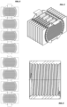
- the blank is bent by 180°, so that a Cylinder package is created from superimposed parallel meander sheets, the distance between which, for example approx. 3 mm, is maintained by the webs (cf. Fig. 2 and 3 ).
- the individual heating grid structure levels can be cut individually and welded together. This would result in a strip-shaped blank, but rather individual circular sheet segments.
- webs for handling during the manufacturing process can be attached to the heating grid structure levels (see Figures 4 and 5 opposite Fig. 1 and 3 ) which are separated after bending or welding or before assembly (step c).
- the finished electrical heating element is then inserted into the cylindrical structure (see Fig. 6 ), whereby this can be done in particular by screwing or turning (cf. Figures 7, 8 and 9 ).
- the cylindrical structure which also serves as an insulator, is in Fig. 6 shown and provided with an internal thread.
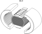
- the cylindrical structure can alternatively be formed from two half-shells which, when put together, form the cylindrical structure (cf. Fig. 10 ).
- the cylindrical structure can have an arrangement of grooves on its inner wall for receiving the two or more spaced meander-shaped heating grid structure planes (cf. Fig. 10 ).
- This design allows for particularly simple assembly, namely by inserting or placing the electric heating element into a first of the half-shells and then assembling the second half-shell with the first.
- the electrical heating element blank During production of the electrical heating element blank, it is possible to design corresponding heating grid structure levels or regions thereof with different dimensions, so that, for example, thicker conductor cross-sections in certain defined areas can transfer different amounts of heat to the passing gas. Furthermore, the flow can be specifically influenced by cutting or punching out adjacent heating grid structure levels (and pre-selecting them during welding) in such a way that the openings of adjacent heating grid structure levels do not coincide with one another with respect to the flow direction.
- the individual heating grid structure levels can also have diffuser elements that do not establish contact between the individual conductors but influence the flow to increase turbulence (not shown).
- This individual design can vary from level to level of the heating grid structure, so that by specifically influencing the flow, a homogenously heated gas is ultimately discharged from the gas flow heater, which is then made available for further processing.
- the channel structure inside can be varied in this way, resulting in corresponding homogenization. In particular, this allows for great variability in the design of the channel and support structure that can be formed in this way.
- Channel structures can be designed inside, which can then have a positive influence on the heating of the flowing gas.
- complex internal channel structures can also be created, for example to calm flows or to deliberately make them turbulent. Using computer simulations, such bottlenecks for the gas flow can be calculated and adjusted accordingly, as this depends on many factors such as the gas inlet area, gas outlet area, flow rate, etc.
- the individual heating conductors of the meandering electrical heating elements can be arranged at different densities.
- an inhomogeneous distribution of heating conductors in one plane can be realized, which can counteract possible uneven gas heating, for example, in the edge areas of the heater.
- the heater and the heating elements can be designed according to the flow profiles.
- Gas heating can also be optimized in the same way, as the inventive solution, using CNC-supported processes, allows for rapid validation of simulated temperature distributions of the gas flow heater.
Landscapes
- Resistance Heating (AREA)
Claims (10)
- Chauffe-eau électrique à écoulement de gaz pour la technologie des cellules à oxyde solide, comprenant au moins une structure cylindrique dans laquelle est formé au moins un canal pour la conduite du gaz et au moins un élément chauffant électrique est disposé dans le canal de la structure cylindrique,
de la chaleur pouvant être transmise par l'élément chauffant électrique à un gaz s'écoulant à travers le canal pour chauffer le gaz et pour obtenir des températures de gaz de 800 °C à 1200 °C, dans lequel- l'élément chauffant électrique présente, perpendiculairement à la direction d'écoulement du canal, deux ou plusieurs plans de structure de grille chauffante espacés, réalisés à la manière de méandres, et- les deux ou plusieurs plans de structure de grille chauffante en forme de méandres espacés sont disposés l'un après l'autre dans le canal dans la direction d'écoulement, les différents plans de structure de grille chauffante en forme de méandres espacés étant reliés entre eux en forme de méandres par une liaison intermédiaire conductrice de l'électricité et le premier ainsi que le dernier des plans de structure de grille chauffante en forme de méandres espacés présentant un connecteur électrique, et- la structure cylindrique est formée sur sa paroi intérieure pour recevoir les deux ou plusieurs plans de structure de grille chauffante espacés et formés en meanders. - Chauffe-eau électrique à gaz selon la revendication 1,
caractérisé en ce que
l'élément chauffant électrique est formé d'une seule pièce ou d'un seul tenant ou d'un seul matériau. - Chauffe-eau électrique à gaz selon la revendication 1 ou 2,
caractérisé en ce que
la structure cylindrique est dotée, du côté intérieur, d'une grille chauffante pour recevoir les deux ou plusieurs plans de structure de grille chauffante espacés et conçus en forme de meanders- un filetage intérieur, de préférence un filetage intérieur à deux filets, l'élément chauffant électrique pouvant être introduit ou extrait dans la structure cylindrique par un mouvement de rotation de l'élément chauffant électrique par rapport à celle-ci,
ou- d'un agencement de rainures, l'élément chauffant électrique pouvant être inséré ou retiré de la structure cylindrique lorsque la demi-coque en deux parties est ouverte. - Chauffe-eau électrique à gaz selon l'une quelconque des revendications précédentes, caractérisé en ce que
les différents plans de structure de grille chauffante en forme de méandres, reliés entre eux et espacés, sont disposés à égale distance dans le sens de l'écoulement. - Chauffe-eau électrique à gaz selon l'une quelconque des revendications précédentes, caractérisé en ce que
l'élément de chauffage électrique présente au moins une des caractéristiques choisies parmi les caractéristiques suivantes:- les différents plans de structure de grille chauffante espacés et formés en méandres présentent une enveloppe circulaire;- les différents plans de structure de grille chauffante espacés et formés en méandres sont plus larges dans leurs zones de bordure que dans leurs zones intérieures;- la section transversale des conducteurs des liaisons intermédiaires est nettement plus grande que les sections transversales des conducteurs des plans de structure de grille chauffante espacés et formés en meanders. - Chauffe-eau électrique à gaz selon l'une quelconque des revendications précédentes, caractérisé en ce que
la structure cylindrique est conçue comme un isolateur. - Chauffe-eau électrique à gaz selon l'une quelconque des revendications précédentes, caractérisé en ce que
la structure cylindrique est formée de céramique technique et/ou de béton et/ou d'alumine. - Chauffe-eau électrique à gaz selon l'une quelconque des revendications précédentes, caractérisé en ce que
l'élément de chauffage électrique est dépourvu de structure de support, de sorte que l'élément de chauffage électrique est exclusivement supporté dans le logement de la structure cylindrique. - Chauffe-eau électrique à gaz selon l'une quelconque des revendications précédentes, caractérisé en ce que
les plans de structure de grille chauffante voisins sont formés de telle sorte que leurs ouvertures ne coïncident pas entre elles par rapport à la direction d'écoulement et/ou les plans de structure de grille chauffante sont pourvus d'éléments de diffusion. - Procédé de fabrication d'un radiateur à gaz pour la fabrication d'un radiateur électrique à gaz pour la technologie des cellules à oxyde solide selon l'une quelconque des revendications précédentes, comprenant au moins les étapes suivantes:a) Fabrication de la structure cylindrique;b) fabriquer l'élément de chauffage électrique par pliage au moyen des étapes suivantes:- Fabrication d'une ébauche par estampage et/ou par laser et/ou par découpage dans une tôle, des plans de structure de grille chauffante en forme de méandres, reliés entre eux par des liaisons intermédiaires, étant formés;- Pliage de l'ébauche de respectivement 180° dans la zone des liaisons intermédiaires, de sorte qu'il se forme une structure cylindrique constituée de plans parallèles de structures de grille chauffante en forme de méandres, dont l'écartement est maintenu par les liaisons intermédiaires;c) Montage du radiateur à gaz au moyen des étapes suivantes:- visser ou insérer l'élément chauffant électrique dans la structure cylindrique; et établir un contact électrique avec l'élément chauffant électrique.
Priority Applications (2)
| Application Number | Priority Date | Filing Date | Title |
|---|---|---|---|
| EP20213106.6A EP4013187B1 (fr) | 2020-12-10 | 2020-12-10 | Chauffage électrique de gaz et procédé de fabrication de chauffage électrique de gaz |
| DK20213106.6T DK4013187T3 (da) | 2020-12-10 | 2020-12-10 | Elektrisk gasstrømningsvarmer og fremgangsmåde til fremstilling af en gasstrømningsvarmer |
Applications Claiming Priority (1)
| Application Number | Priority Date | Filing Date | Title |
|---|---|---|---|
| EP20213106.6A EP4013187B1 (fr) | 2020-12-10 | 2020-12-10 | Chauffage électrique de gaz et procédé de fabrication de chauffage électrique de gaz |
Publications (2)
| Publication Number | Publication Date |
|---|---|
| EP4013187A1 EP4013187A1 (fr) | 2022-06-15 |
| EP4013187B1 true EP4013187B1 (fr) | 2025-03-12 |
Family
ID=73793081
Family Applications (1)
| Application Number | Title | Priority Date | Filing Date |
|---|---|---|---|
| EP20213106.6A Active EP4013187B1 (fr) | 2020-12-10 | 2020-12-10 | Chauffage électrique de gaz et procédé de fabrication de chauffage électrique de gaz |
Country Status (2)
| Country | Link |
|---|---|
| EP (1) | EP4013187B1 (fr) |
| DK (1) | DK4013187T3 (fr) |
Families Citing this family (2)
| Publication number | Priority date | Publication date | Assignee | Title |
|---|---|---|---|---|
| DE102022125694B4 (de) * | 2022-10-05 | 2025-05-22 | Tenneco Gmbh | Heizelement und Heizvorrichtung |
| AT526909B1 (de) * | 2023-02-03 | 2025-06-15 | Ebner Ind Ofenbau | Heizvorrichtung |
Family Cites Families (3)
| Publication number | Priority date | Publication date | Assignee | Title |
|---|---|---|---|---|
| DE102014102474A1 (de) | 2014-02-25 | 2015-08-27 | Sandvik Materials Technology Deutschland Gmbh | Heizelement und Prozessheizer |
| US9980518B1 (en) * | 2014-12-04 | 2018-05-29 | Matthew Isaac Most | Heating element for a portable vaporizer |
| CN107580460B (zh) * | 2015-04-23 | 2021-11-02 | 奥驰亚客户服务有限责任公司 | 用于电子烟设备的加热元件 |
-
2020
- 2020-12-10 EP EP20213106.6A patent/EP4013187B1/fr active Active
- 2020-12-10 DK DK20213106.6T patent/DK4013187T3/da active
Also Published As
| Publication number | Publication date |
|---|---|
| EP4013187A1 (fr) | 2022-06-15 |
| DK4013187T3 (da) | 2025-06-16 |
Similar Documents
| Publication | Publication Date | Title |
|---|---|---|
| EP1790916B1 (fr) | Dispositif de chauffage électrique avec un élément de tolérance et de chauffage à effet CTP | |
| DE102019127691B4 (de) | Verfahren zur Herstellung einer elektrischen Heizvorrichtungmit einem elektrischen Heizelement | |
| WO2013104754A1 (fr) | Corps en nid d'abeilles pouvant être chauffé électriquement, composé de plusieurs couches de tôles reliées électriquement à une broche de connexion | |
| WO2015078704A1 (fr) | Dispositif de chauffage | |
| EP4013187A1 (fr) | Chauffage électrique de gaz et procédé de fabrication de chauffage électrique de gaz | |
| WO2021170331A1 (fr) | Dispositif de chauffage | |
| EP1627441A1 (fr) | Pile a combustible et systeme de chauffage de pile a combustible | |
| DE102018103048B4 (de) | Elektrische Heizvorrichtung | |
| EP4223991B1 (fr) | Dispositif de chauffage électrique de gaz d'échappement | |
| EP3494294B1 (fr) | Corps alvéolaire pouvant être chauffé électriquement pour le traitement des gaz d'échappement comportant une pluralité d'éléments chauffants | |
| DE202020101182U1 (de) | Elektrische Heizvorrichtung | |
| DE102019127692B4 (de) | Verfahren zur Herstellung eines elektrischen Rohrheizkörpers | |
| EP3864263B1 (fr) | Dispositif pour traitement des gaz d'échappement | |
| DE102021131364A1 (de) | Elektrische Heizvorrichtung eines Abgassystems | |
| DE102004016434A1 (de) | Elektrischer Fluidheizer | |
| DE3619919C2 (de) | Quarz-Infrarotstrahler | |
| EP2348251A2 (fr) | Dispositif de chauffage d'un liquide et procédé de fabrication d'un dispositif de chauffage pour le chauffage d'un liquide | |
| DE102018200433B4 (de) | Elektrische Heizvorrichtung | |
| EP1510688B1 (fr) | Dispositif de chauffage pour un milieu à chauffer | |
| DE102021132931B4 (de) | Abgasheizanordnung für eine Abgasanlage einer Brennkraftmaschine | |
| DE102022133174A1 (de) | Kühlvorrichtung zur Kühlung elektronischer Komponenten, Verwendung derselben und Verfahren zu ihrer Herstellung | |
| EP2506660B1 (fr) | Caloporteur | |
| DE102025143951A1 (de) | Elektrische Heizvorrichtung | |
| EP1947908A1 (fr) | Agencement de filament chauffant destiné au chauffage de matières gazeuses s'écoulant | |
| DE102017121183A1 (de) | Heizvorrichtung sowie Verfahren zur Herstellung einer Heizvorrichtung |
Legal Events
| Date | Code | Title | Description |
|---|---|---|---|
| PUAI | Public reference made under article 153(3) epc to a published international application that has entered the european phase |
Free format text: ORIGINAL CODE: 0009012 |
|
| STAA | Information on the status of an ep patent application or granted ep patent |
Free format text: STATUS: THE APPLICATION HAS BEEN PUBLISHED |
|
| AK | Designated contracting states |
Kind code of ref document: A1 Designated state(s): AL AT BE BG CH CY CZ DE DK EE ES FI FR GB GR HR HU IE IS IT LI LT LU LV MC MK MT NL NO PL PT RO RS SE SI SK SM TR |
|
| STAA | Information on the status of an ep patent application or granted ep patent |
Free format text: STATUS: REQUEST FOR EXAMINATION WAS MADE |
|
| 17P | Request for examination filed |
Effective date: 20221209 |
|
| RBV | Designated contracting states (corrected) |
Designated state(s): AL AT BE BG CH CY CZ DE DK EE ES FI FR GB GR HR HU IE IS IT LI LT LU LV MC MK MT NL NO PL PT RO RS SE SI SK SM TR |
|
| P01 | Opt-out of the competence of the unified patent court (upc) registered |
Effective date: 20230512 |
|
| RAP3 | Party data changed (applicant data changed or rights of an application transferred) |
Owner name: SUNFIRE GMBH |
|
| GRAP | Despatch of communication of intention to grant a patent |
Free format text: ORIGINAL CODE: EPIDOSNIGR1 |
|
| STAA | Information on the status of an ep patent application or granted ep patent |
Free format text: STATUS: GRANT OF PATENT IS INTENDED |
|
| GRAS | Grant fee paid |
Free format text: ORIGINAL CODE: EPIDOSNIGR3 |
|
| GRAA | (expected) grant |
Free format text: ORIGINAL CODE: 0009210 |
|
| STAA | Information on the status of an ep patent application or granted ep patent |
Free format text: STATUS: THE PATENT HAS BEEN GRANTED |
|
| RIC1 | Information provided on ipc code assigned before grant |
Ipc: H05B 3/44 20060101AFI20250109BHEP |
|
| INTG | Intention to grant announced |
Effective date: 20250117 |
|
| AK | Designated contracting states |
Kind code of ref document: B1 Designated state(s): AL AT BE BG CH CY CZ DE DK EE ES FI FR GB GR HR HU IE IS IT LI LT LU LV MC MK MT NL NO PL PT RO RS SE SI SK SM TR |
|
| REG | Reference to a national code |
Ref country code: GB Ref legal event code: FG4D Free format text: NOT ENGLISH |
|
| REG | Reference to a national code |
Ref country code: CH Ref legal event code: EP |
|
| REG | Reference to a national code |
Ref country code: DE Ref legal event code: R096 Ref document number: 502020010573 Country of ref document: DE |
|
| REG | Reference to a national code |
Ref country code: IE Ref legal event code: FG4D Free format text: LANGUAGE OF EP DOCUMENT: GERMAN |
|
| REG | Reference to a national code |
Ref country code: DE Ref legal event code: R081 Ref document number: 502020010573 Country of ref document: DE Owner name: SUNFIRE SE, DE Free format text: FORMER OWNER: ANMELDERANGABEN UNKLAR / UNVOLLSTAENDIG, 80297 MUENCHEN, DE |
|
| RAP4 | Party data changed (patent owner data changed or rights of a patent transferred) |
Owner name: SUNFIRE AG |
|
| RAP2 | Party data changed (patent owner data changed or rights of a patent transferred) |
Owner name: SUNFIRE SE |
|
| REG | Reference to a national code |
Ref country code: DK Ref legal event code: T3 Effective date: 20250610 |
|
| REG | Reference to a national code |
Ref country code: SE Ref legal event code: TRGR |
|
| PG25 | Lapsed in a contracting state [announced via postgrant information from national office to epo] |
Ref country code: RS Free format text: LAPSE BECAUSE OF FAILURE TO SUBMIT A TRANSLATION OF THE DESCRIPTION OR TO PAY THE FEE WITHIN THE PRESCRIBED TIME-LIMIT Effective date: 20250612 |
|
| PG25 | Lapsed in a contracting state [announced via postgrant information from national office to epo] |
Ref country code: FI Free format text: LAPSE BECAUSE OF FAILURE TO SUBMIT A TRANSLATION OF THE DESCRIPTION OR TO PAY THE FEE WITHIN THE PRESCRIBED TIME-LIMIT Effective date: 20250312 |
|
| PG25 | Lapsed in a contracting state [announced via postgrant information from national office to epo] |
Ref country code: ES Free format text: LAPSE BECAUSE OF FAILURE TO SUBMIT A TRANSLATION OF THE DESCRIPTION OR TO PAY THE FEE WITHIN THE PRESCRIBED TIME-LIMIT Effective date: 20250312 |
|
| REG | Reference to a national code |
Ref country code: LT Ref legal event code: MG9D |
|
| PG25 | Lapsed in a contracting state [announced via postgrant information from national office to epo] |
Ref country code: NO Free format text: LAPSE BECAUSE OF FAILURE TO SUBMIT A TRANSLATION OF THE DESCRIPTION OR TO PAY THE FEE WITHIN THE PRESCRIBED TIME-LIMIT Effective date: 20250612 |
|
| PG25 | Lapsed in a contracting state [announced via postgrant information from national office to epo] |
Ref country code: HR Free format text: LAPSE BECAUSE OF FAILURE TO SUBMIT A TRANSLATION OF THE DESCRIPTION OR TO PAY THE FEE WITHIN THE PRESCRIBED TIME-LIMIT Effective date: 20250312 |
|
| REG | Reference to a national code |
Ref country code: NL Ref legal event code: MP Effective date: 20250312 |
|
| PG25 | Lapsed in a contracting state [announced via postgrant information from national office to epo] |
Ref country code: LV Free format text: LAPSE BECAUSE OF FAILURE TO SUBMIT A TRANSLATION OF THE DESCRIPTION OR TO PAY THE FEE WITHIN THE PRESCRIBED TIME-LIMIT Effective date: 20250312 |
|
| PG25 | Lapsed in a contracting state [announced via postgrant information from national office to epo] |
Ref country code: BG Free format text: LAPSE BECAUSE OF FAILURE TO SUBMIT A TRANSLATION OF THE DESCRIPTION OR TO PAY THE FEE WITHIN THE PRESCRIBED TIME-LIMIT Effective date: 20250312 Ref country code: GR Free format text: LAPSE BECAUSE OF FAILURE TO SUBMIT A TRANSLATION OF THE DESCRIPTION OR TO PAY THE FEE WITHIN THE PRESCRIBED TIME-LIMIT Effective date: 20250613 |
|
| PG25 | Lapsed in a contracting state [announced via postgrant information from national office to epo] |
Ref country code: NL Free format text: LAPSE BECAUSE OF FAILURE TO SUBMIT A TRANSLATION OF THE DESCRIPTION OR TO PAY THE FEE WITHIN THE PRESCRIBED TIME-LIMIT Effective date: 20250312 |
|
| PG25 | Lapsed in a contracting state [announced via postgrant information from national office to epo] |
Ref country code: SM Free format text: LAPSE BECAUSE OF FAILURE TO SUBMIT A TRANSLATION OF THE DESCRIPTION OR TO PAY THE FEE WITHIN THE PRESCRIBED TIME-LIMIT Effective date: 20250312 |
|
| PG25 | Lapsed in a contracting state [announced via postgrant information from national office to epo] |
Ref country code: PT Free format text: LAPSE BECAUSE OF FAILURE TO SUBMIT A TRANSLATION OF THE DESCRIPTION OR TO PAY THE FEE WITHIN THE PRESCRIBED TIME-LIMIT Effective date: 20250714 |
|
| PG25 | Lapsed in a contracting state [announced via postgrant information from national office to epo] |
Ref country code: PL Free format text: LAPSE BECAUSE OF FAILURE TO SUBMIT A TRANSLATION OF THE DESCRIPTION OR TO PAY THE FEE WITHIN THE PRESCRIBED TIME-LIMIT Effective date: 20250312 Ref country code: IT Free format text: LAPSE BECAUSE OF FAILURE TO SUBMIT A TRANSLATION OF THE DESCRIPTION OR TO PAY THE FEE WITHIN THE PRESCRIBED TIME-LIMIT Effective date: 20250312 |
|
| PG25 | Lapsed in a contracting state [announced via postgrant information from national office to epo] |
Ref country code: CZ Free format text: LAPSE BECAUSE OF FAILURE TO SUBMIT A TRANSLATION OF THE DESCRIPTION OR TO PAY THE FEE WITHIN THE PRESCRIBED TIME-LIMIT Effective date: 20250312 Ref country code: EE Free format text: LAPSE BECAUSE OF FAILURE TO SUBMIT A TRANSLATION OF THE DESCRIPTION OR TO PAY THE FEE WITHIN THE PRESCRIBED TIME-LIMIT Effective date: 20250312 |
|
| PG25 | Lapsed in a contracting state [announced via postgrant information from national office to epo] |
Ref country code: RO Free format text: LAPSE BECAUSE OF FAILURE TO SUBMIT A TRANSLATION OF THE DESCRIPTION OR TO PAY THE FEE WITHIN THE PRESCRIBED TIME-LIMIT Effective date: 20250312 |
|
| PG25 | Lapsed in a contracting state [announced via postgrant information from national office to epo] |
Ref country code: SK Free format text: LAPSE BECAUSE OF FAILURE TO SUBMIT A TRANSLATION OF THE DESCRIPTION OR TO PAY THE FEE WITHIN THE PRESCRIBED TIME-LIMIT Effective date: 20250312 |
|
| PG25 | Lapsed in a contracting state [announced via postgrant information from national office to epo] |
Ref country code: IS Free format text: LAPSE BECAUSE OF FAILURE TO SUBMIT A TRANSLATION OF THE DESCRIPTION OR TO PAY THE FEE WITHIN THE PRESCRIBED TIME-LIMIT Effective date: 20250712 |
|
| REG | Reference to a national code |
Ref country code: DE Ref legal event code: R097 Ref document number: 502020010573 Country of ref document: DE |
|
| PGFP | Annual fee paid to national office [announced via postgrant information from national office to epo] |
Ref country code: GB Payment date: 20251218 Year of fee payment: 6 |
|
| PGFP | Annual fee paid to national office [announced via postgrant information from national office to epo] |
Ref country code: DK Payment date: 20251217 Year of fee payment: 6 |
|
| PLBE | No opposition filed within time limit |
Free format text: ORIGINAL CODE: 0009261 |
|
| STAA | Information on the status of an ep patent application or granted ep patent |
Free format text: STATUS: NO OPPOSITION FILED WITHIN TIME LIMIT |
|
| PGFP | Annual fee paid to national office [announced via postgrant information from national office to epo] |
Ref country code: SE Payment date: 20251217 Year of fee payment: 6 |
|
| REG | Reference to a national code |
Ref country code: CH Ref legal event code: L10 Free format text: ST27 STATUS EVENT CODE: U-0-0-L10-L00 (AS PROVIDED BY THE NATIONAL OFFICE) Effective date: 20260121 |
|
| 26N | No opposition filed |
Effective date: 20251215 |
|
| PGFP | Annual fee paid to national office [announced via postgrant information from national office to epo] |
Ref country code: DE Payment date: 20251222 Year of fee payment: 6 |