EP4013190B1 - Dispositif de circuit pour un dispositif de cuisson, en particulier une plaque de cuisson, en particulier une plaque de cuisson par induction et dispositif de cuisson, en particulier une plaque de cuisson, en particulier une plaque de cuisson par induction - Google Patents
Dispositif de circuit pour un dispositif de cuisson, en particulier une plaque de cuisson, en particulier une plaque de cuisson par induction et dispositif de cuisson, en particulier une plaque de cuisson, en particulier une plaque de cuisson par induction Download PDFInfo
- Publication number
- EP4013190B1 EP4013190B1 EP20213766.7A EP20213766A EP4013190B1 EP 4013190 B1 EP4013190 B1 EP 4013190B1 EP 20213766 A EP20213766 A EP 20213766A EP 4013190 B1 EP4013190 B1 EP 4013190B1
- Authority
- EP
- European Patent Office
- Prior art keywords
- power
- current
- unit
- phase
- conversion unit
- Prior art date
- Legal status (The legal status is an assumption and is not a legal conclusion. Google has not performed a legal analysis and makes no representation as to the accuracy of the status listed.)
- Active
Links
Images
Classifications
-
- H—ELECTRICITY
- H05—ELECTRIC TECHNIQUES NOT OTHERWISE PROVIDED FOR
- H05B—ELECTRIC HEATING; ELECTRIC LIGHT SOURCES NOT OTHERWISE PROVIDED FOR; CIRCUIT ARRANGEMENTS FOR ELECTRIC LIGHT SOURCES, IN GENERAL
- H05B6/00—Heating by electric, magnetic or electromagnetic fields
- H05B6/02—Induction heating
- H05B6/06—Control, e.g. of temperature, of power
- H05B6/062—Control, e.g. of temperature, of power for cooking plates or the like
-
- H—ELECTRICITY
- H05—ELECTRIC TECHNIQUES NOT OTHERWISE PROVIDED FOR
- H05B—ELECTRIC HEATING; ELECTRIC LIGHT SOURCES NOT OTHERWISE PROVIDED FOR; CIRCUIT ARRANGEMENTS FOR ELECTRIC LIGHT SOURCES, IN GENERAL
- H05B1/00—Details of electric heating devices
- H05B1/02—Automatic switching arrangements specially adapted to apparatus ; Control of heating devices
- H05B1/0227—Applications
- H05B1/0252—Domestic applications
- H05B1/0258—For cooking
- H05B1/0261—For cooking of food
- H05B1/0266—Cooktops
Definitions
- the present invention relates to a circuit device for a cooking device, in particular cooking hob, more in particular induction cooking hob and to a cooking device, in particular cooking hob, more in particular induction cooking hob.
- Documents EP 2 007 174 A1 , FR 2 875 370 A1 , EP 3 557 753 A1 , US 2011/147375 A1 and DE 10 2005 044466A1 disclose cooking devices with corresponding circuit devices according to the prior art.
- Circuit devices for a cooking device in particular cooking hob, more in particular induction cooking hob, for example induction boards, are supplied from mains current (or: AC grid voltage), by a single current/voltage phase or multiple current/voltage phases.
- mains current or: AC grid voltage
- frequency converting means can derive sinusoidal currents for injecting in induction elements, for example coils.
- output direct currents are generated for supplying electronics and for driving frequency converting means, in particular inverters.
- the invention relates, in claim 1, to a circuit device for a cooking device, in particular cooking hob, more in particular induction cooking hob, the circuit device comprising
- the first output direct current or one of the first output direct currents of the first power unit is or can be the second input direct current of the second power unit.
- the first power unit can supply each other power unit with a direct current.
- An input direct current can in particular be a DC input current.
- An input alternating current can in particular be an AC input current.
- An output direct current can in particular be a DC output current.
- An alternating current can in particular be a current which is supplied by an alternating voltage or AC voltage, in particular between 100V and 250V or between 85V and 265V, with an input frequency, in particular between 45Hz and 130Hz, more in particular of 50 Hz or 65Hz, as well as a current phase.
- the current conversion unit can in particular be a DC/DC converter which converts a direct input voltage into one or more direct output voltages.
- the current conversion unit can in particular be an AC/DC converter which converts an alternating input voltage into one or more direct output voltages.
- a main current phase can in particular be an alternating current which is supplied with a predefined current phase.
- Such a current phase can be phase-shifted, for example by 120°, to different mains current phases.
- electrical power can be supplied by two or three different current phases which are phase shifted by 120° or 180°.
- a mains current is in particular a current which is supplied by an external power net or supply net.
- a load can in particular be a control unit or a fan.
- a load can in particular be a low power unit which is preferably supplied with power by a supply voltage of 18V or less.
- At least one or each power unit is a power board, in particular mounted as or on a printed circuit board.
- a printed circuit board can allow a good isolation of the different mains current phases.
- the usage of printed circuit boards can allow an efficient pre-mounting of the power units for the different mains current phases.
- At least one or each of the current conversion units is an insulated current conversion unit, in particular an insulated AC/DC conversion unit and/or an insulated DC/DC conversion unit. This enables or can enable a good isolation of the different current phases.
- the first current conversion unit is an AC/DC converter that outputs one, at least one, two or at least two direct voltages, in particular at least two different direct voltages, for example 5V and 18V, and/or currents from the first mains current phase, in particular from a single phase-neutral AC voltage or from a phase-phase AC voltage.
- a phase-phase AC voltage is or can be a typical mains voltage, for example in the United States of America.
- the first current conversion unit in particular by supplying at least a second current conversion unit and/or a third current conversion unit with electrical power, generates supply voltages for multiple loads, in particular for multiple low power loads and/or control units, in particular on at least a second power unit and/or a third power unit or each power unit and/or referred to different mains current phases and/or to different phase-neutral voltages and/or to different phase-phase AC voltages.
- This enables or can enable a power supply for the loads from the first power unit to at least one further power unit.
- At least one of the current conversion units is or are DC/DC conversion units. This enables or can enable simpler and/or less complex current conversion units, as no AC/DC conversion is required in these current conversion units.
- each power unit comprises at least one or only a single current conversion unit, in particular at least one or a single low power current conversion unit, for supplying currents and/or voltages to the loads, in particular the low power loads. This enables or can enable less current conversion units, as no further current conversion units are required in these power units.
- only the first current conversion unit is supplied by a mains current phase, and the second current conversion unit and/or third current conversion unit is/are only supplied by the first current conversion unit. This enables or can enable simpler and/or less complex current conversion units, as no AC/DC conversion is required in these current conversion units.
- At least one or each current conversion unit outputs at least two output voltages, in particular two, at least two, three or at least three different output voltages, in particular for supplying different loads. This enables or can enable the power supply of a larger variety of loads.
- the first power unit is electrically connected with each of the other power units, in particular with the second power unit and/or third power unit, for supplying voltages for loads, in particular for low power loads and/or control units, in particular on each power unit and/or power units referred to different mains current phases and/or to different phase-neutral voltages and/or to different phase-phase AC voltages.
- This enables or can enable simpler and/or less complex current conversion units, as no AC/DC conversion is required in these current conversion units.
- the first current conversion unit of the first power unit is electrically connected with the current conversion units of each of the other power units for supplying voltages for all control units, in particular on each power unit and/or on power units referred to different mains current phases and/or to different phase-neutral voltages and/or to different phase-phase AC voltages.
- a control unit is provided to turn-on or turn-off current conversion units, in particular insulated power supplies, of each power unit or of the second power unit and/or the third power unit.
- the total power from the frequency converting means of each mains current phase is limited by a control unit to a predetermined maximum power, which in particular limits the individual power of each frequency converting means to ensure that total power is below the or a rated power of each mains current phase. This enables or can enable the operation of, in particular a single, frequency converting means with a higher power.
- the predetermined maximum power which limits the power of the frequency converting means on each current phase such that that the total power, is below the or a maximum rated power of each current phase.
- the cooking device comprises induction elements, wherein each power unit supplies or is configured to supply at least one induction element, in particular induction coil, with electrical power by a frequency converting means, preferably to generate heating energy for heating a cooking vessel disposed on the induction element or coil.
- each power unit supplies or is configured to supply at least one induction element, in particular induction coil, with electrical power by a frequency converting means, preferably to generate heating energy for heating a cooking vessel disposed on the induction element or coil.
- each power unit by a different current phase, one, at least one, two, at least two, three, at least three, four or at least four frequency converting means are supplied with electrical power.
- each power unit comprises frequency converting means for supplying at least one induction element with electrical power from the mains current phase supplying the power unit with electrical power.
- a frequency converting means is a means or inverter or generator for converting an input current with an input frequency, in particular between 45Hz and 130Hz, more in particular of 50Hz or 65Hz, into an output current with a high frequency, in particular with a frequency between 10kHz and 100kHz. This enables or can enable to provide heating energy to the induction elements.
- a frequency converting means comprises at least one, in particular common, rectifying means and/or, in particular in series, at least one frequency generation means driven with a driving frequency, wherein the driving frequency is supplied with electrical power by a control unit, wherein in particular the control unit is supplied with electrical power by a or the current conversion unit of the power unit.
- the invention relates to a cooking device, in particular cooking hob, more in particular induction cooking hob, with a circuit device according to the invention.
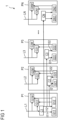
- FIG. 1 shows a circuit device 1 according to an embodiment of the present invention.
- the circuit device 1 is intended for a cooking device, in particular cooking hob, more in particular induction cooking hob.
- the circuit device 1 comprises at least two, in particular two, three or at least three power units P1, P2, .. PN, each power unit supplied with electrical power by a different mains current phase L1, L2, .. LN.
- Each power unit P1, P2, .. PN comprises frequency converting means G11 .. GNM, each for supplying at least one induction element with electrical power to generate heating power.
- Each power unit P1, P2, .. PM comprises at least one current conversion unit C1 .. CN for converting an input direct or alternating current into one, at least one, two or at least two output direct currents.
- Each power unit P1, P2, .. PN comprises at least one load or at least two loads, in particular one or more low-power loads and/or control units, supplied or to be supplied with electrical power by the output direct current, an output direct current or the different output direct currents from the current conversion unit.
- the first power unit P1 comprises a first current conversion unit C1, for converting an alternating current from a first mains current phase L1 into two first output direct currents I11 and 112.
- a second current conversion unit C2 of a second power unit P2 is supplied for converting the first output direct current I12 into two output direct currents I21 and I22.
- one of the first output direct currents is or can be the second input direct current.
- the first power unit P1 can supply each other power unit with a direct current.
- a third current conversion unit C3 of a third power unit P3 is supplied for converting the first output direct current I12 into two output direct currents I31 and I32.
- An input direct current is, for power units P2 and P3, a DC input current.
- An input alternating current is, for power unit P1, an AC input current.
- An output direct current is a DC output current.
- An alternating current can be a current which is supplied by an alternating voltage or AC voltage, in particular between 100V and 250V or between 85V and 265V.
- Each of the current conversion units C2, C3 .. CN is a DC/DC converter which converts a direct input voltage into two direct output voltages.
- the current conversion unit C1 is an AC/DC converter which converts an alternating input voltage L1 into two direct output voltages.
- a main current phase can in particular be an alternating current which is supplied with a predefined current phase.
- Such a current phase can be phase-shifted, for example by 120°, to different mains current phases.
- electrical power can be supplied by two or three different current phases which are phase shifted by 120° or 180°.
- a mains current is a current which is supplied by an external power net or supply net.
- a load can be a control unit or a fan.
- a load can in particular be a low power unit which is preferably supplied with power by a supply voltage of 18V or less.
- Each power unit P1, P2, .. PN is a power board, in particular mounted as or on a printed circuit board.
- a printed circuit board can allow a good isolation of the different mains current phases.
- the usage of printed circuit boards can allow an efficient pre-mounting of the power units for the different mains current phases.
- Each of the current conversion units C1 .. CN is an insulated current conversion unit, in particular an insulated AC/DC conversion unit C1 and insulated DC/DC conversion units C2 .. CN.
- the first current conversion unit C1 is an AC/DC converter that outputs two direct voltages, in particular two different direct voltages, for example 5V and 18V, and currents from the first mains current phase L1, in particular from a single phase-neutral AC voltage or from a phase-phase AC voltage.
- the first current conversion unit C1 by supplying at least a second current conversion unit C2 and a third current conversion unit C3, generates supply voltages for multiple loads, in particular multiple low power loads and/or control units, on at least a second power unit P2 and a third power unit P3 or each power unit P1 .. PN, referred to different mains current phases L1, L2, .. LN and to different phase-neutral voltages and/or to different phase-phase AC voltages.
- At least one of the current conversion units C1 .. CN, in particular the conversion units C2, C3 of the second power unit P2 and a third power unit P3, are DC/DC conversion units.
- Each power unit P1 .. PN comprises at least one or only a single current conversion unit C1 .. CN, in particular at least one or a single low power current conversion unit, for supplying currents and/or voltages to the loads, in particular the low power loads.
- Each current conversion unit C1 .. CN outputs at least two output voltages, in particular two different output voltages, in particular for supplying different loads.
- the first power unit P1 is electrically connected with each of the other power units P2 .. PN, in particular with the second power unit P2 and third power unit P3, for supplying voltages for loads, in particular low power loads and/or control units, on each power unit P1 .. PN and power units referred to different mains current phases L1 .. LN and to different phase-neutral voltages and/or to different phase-phase AC voltages.
- the first current conversion unit of the first power unit is electrically connected with the current conversion units of each of the other power units for supplying voltages for all control units, on each power unit and on power units referred to different mains current phases and to different phase-neutral voltages and/or to different phase-phase AC voltages.
- the circuit device 1 comprises a control unit to turn-on or turn-off current conversion units, in particular insulated power supplies, of each power unit or of the second power unit and/or the third power unit.
- the total power from the frequency converting means G11 .. GNM of each mains current phase L1 .. LN is limited by a control unit to a predetermined maximum power, which limits the individual power of each frequency converting means G11 .. GNM to ensure that total power is below the rated power of each mains current phase L1 .. LN.
- the predetermined maximum power which limits the power of the frequency converting means on each current phase such that the total power, is below the maximum rated power of each current phase.
- the circuit device 1 comprises induction elements, wherein each power unit P1 .. PN supplies or is configured to supply at least one induction element with electrical power by a frequency converting means G1M .. GNM.
- each power unit P1 .. PN by a different current phase L1 .. LN, one, at least one, two, at least two, three, at least three, four or at least four frequency converting means G1M .. GNM are supplied with electrical power.
- Each power unit P1, P2, .. PM comprises frequency converting means G1M .. GNM for supplying at least one induction element with electrical power from the mains current phase L1, L2, .. LM supplying the power unit P1, P2, .. PM with electrical power.
- a frequency converting means G1M .. GNM is a means or generator for converting an input current with an input frequency, in particular between 45Hz and 130Hz, more in particular of 50Hz or of 65Hz, into an output current with a high frequency, in particular with a frequency between 10kHz and 100kHz.
- a frequency converting means G1M .. GNM comprises at least one, in particular common, rectifying means and/or, in particular in series, at least one frequency generation means driven with a driving frequency.
- the driving frequency is supplied with electrical power by a control unit, wherein the control unit is supplied with electrical power by the current conversion unit C1 .. CN of the power unit P1 .. PN.
- the circuit device 1 relates to and/or is part of and/or operates a cooking device, in particular cooking hob, more in particular induction cooking hob, with a circuit device 1.
Landscapes
- Physics & Mathematics (AREA)
- Electromagnetism (AREA)
- Engineering & Computer Science (AREA)
- Food Science & Technology (AREA)
- Ac-Ac Conversion (AREA)
- Inverter Devices (AREA)
- Electric Stoves And Ranges (AREA)
- Cookers (AREA)
Claims (15)
- Dispositif à circuit (1) pour un dispositif de cuisson, particulièrement une plaque de cuisson, plus particulièrement une plaque de cuisson à induction, comprenantau moins deux, particulièrement deux, trois ou au moins trois unités de puissance (P1, P2, ..., PN), chaque unité de puissance étant configurée pour être alimentée par de la puissance électrique par une phase de courant de secteur (L1, L2, ..., LN) différente,chaque unité de puissance (P1, P2, ..., PN) comprenant des moyens de conversion de fréquence (G11, ..., GM), chacun étant destiné à alimenter au moins un élément d'induction avec de la puissance électrique pour générer de la puissance de chauffe,chaque unité de puissance (P1, P2, ..., PN) comprenant au moins une unité de conversion de courant (C1, ..., CN) pour convertir un courant continu ou alternatif d'entrée en un, au moins un, deux ou au moins deux courants continus de sortie,chaque unité de puissance (P1, P2, ..., PN) comprenant au moins une charge ou au moins deux charges (D11, ..., DN2), particulièrement une ou plusieurs charges et/ou unités de commande basse puissance, alimentées ou à alimenter par de la puissance électrique par le courant continu de sortie, un courant continu de sortie ou les courants continus de sortie provenant de l'unité de conversion de courant,une première unité de puissance (P1) comprenant une première unité de conversion de courant (C1), particulièrement pour convertir un courant alternatif provenant d'une première phase de courant de secteur (L1) en un, au moins un, deux ou au moins deux premiers courants continus de sortie (I11, ..., IN2), caractérisé en ce quele premier courant continu de sortie ou un des premiers courants continus de sortie (I12) de la première unité de puissance (P1) est configuré pour alimenter au moins une deuxième unité de conversion de courant (C2) d'une deuxième unité de puissance (P2) pour convertir le premier courant continu de sortie (I12) en un, au moins un, deux ou au moins deux deuxièmes courants continus de sortie.
- Dispositif à circuit selon la revendication 1,
au moins une ou chacune des unités de conversion de courant (C1, ..., CN) étant une unité de conversion de courant isolée, particulièrement une unité de conversion CA/CC (C1) isolée et/ou une unité de conversion CC/CC (C2, ..., CN) isolée. - Dispositif à circuit selon l'une quelconque des revendications précédentes,
la première unité de conversion de courant (C1) étant un convertisseur CA/CC qui est capable de délivrer une, au moins une, deux ou au moins deux tensions continues, particulièrement au moins deux tensions continues différentes, par exemple 5 V et 18 V, et/ou des courants provenant de la première phase de courant de secteur (L1), particulièrement provenant d'une tension CA phase-neutre unique ou provenant d'une tension CA phase-phase. - Dispositif à circuit selon l'une quelconque des revendications précédentes, la première unité de conversion de courant (C1), particulièrement en étant configurée pour alimenter au moins une deuxième unité de conversion de courant (C2) et/ou une troisième unité de conversion de courant (C3), étant capable de générer des tensions d'alimentation pour des charges multiples, particulièrement des charges et/ou des unités de commande basse puissance multiples, particulièrement sur au moins une deuxième unité de puissance (P2) et/ou une troisième unité de puissance (P3) ou chaque unité de puissance (P1, ..., PN) et/ou faisant référence à différentes phases de courant de secteur (L1, L2, ..., LN) et/ou à différentes tensions phase-neutre ou à différentes tensions CA phase-phase.
- Dispositif à circuit selon l'une quelconque des revendications précédentes,
au moins une des unités de conversion de courant (C1, ..., CN), particulièrement la ou au moins une unité de conversion de courant (C2, C3) de la deuxième unité de puissance (P2) et/ou d'une troisième unité de puissance (P3), étant une/des unité(s) de conversion CC/CC. - Dispositif à circuit selon l'une quelconque des revendications précédentes,
chaque unité de puissance (P1, ..., Pn) comprenant au moins une unité de conversion ou seulement une unique unité de conversion de courant (C1, ..., CN), particulièrement une unique ou au moins une unité de conversion de courant basse puissance, pour fournir des courants et/ou des tensions aux charges, particulièrement aux charges basse puissance. - Dispositif à circuit selon l'une quelconque des revendications précédentes,
seule la première unité de conversion de courant (C1) étant configurée pour être alimentée par une phase de courant de secteur (L1), et la deuxième unité de conversion de courant (C2) et/ou la troisième unité de conversion de courant (C3) étant seulement configurée(s) pour être alimentées par la première unité de conversion de courant (C1). - Dispositif à circuit selon l'une quelconque des revendications précédentes,
au moins une ou chaque unité de conversion de courant (C1, ..., CN) délivrant au moins une tension de sortie, particulièrement une, deux, au moins deux, trois ou au moins trois tensions de sortie différentes, particulièrement pour alimenter différentes charges. - Dispositif à circuit selon l'une quelconque des revendications précédentes,
la première unité de puissance (P1) étant connectée électriquement à chacune des autres unités de puissance (P2, ..., PN), particulièrement avec la deuxième unité de puissance (P2) et/ou la troisième unité de puissance (P3), pour fournir des tensions pour des charges, particulièrement des charges et/ou unités de commande basse puissance, particulièrement sur chaque unité de puissance (P1, ..., PN) et/ou des unités de puissance faisant référence à différentes phases de courant de secteur (L1, ..., LN) et/ou à différentes tensions phase-neutre et/ou à différentes tensions phase-phase. - Dispositif à circuit selon l'une quelconque des revendications précédentes,
la puissance totale provenant des moyens de conversion de fréquence (G11, ..., GNM) de chaque phase de courant de secteur (L1, ..., LN) étant limitée par une unité de commande à une puissance maximale prédéterminée, qui particulièrement limite la puissance individuelle de chaque moyen de conversion de fréquence (G11, ..., GNM) pour assurer que la puissance totale est en dessous de la puissance nominale de chaque phase de courant de secteur (L1, ..., LN). - Dispositif à circuit selon l'une quelconque des revendications précédentes,
comprenant des éléments à induction, chaque unité de puissance (P1, ..., PN) alimentant ou étant configurée pour alimenter au moins un élément à induction par de la puissance électrique par un moyen de conversion de fréquence (G1M,..., GNM). - Dispositif à circuit selon l'une quelconque des revendications précédentes,
sur chaque unité de puissance (P1, ..., PN), une phase de courant différente (L1, ..., LN) étant configurée pour alimenter un, deux, au moins deux, trois, au moins trois, quatre ou au moins quatre moyens de conversion de fréquence (G1M, ..., GNM) par de la puissance électrique. - Dispositif à circuit selon l'une quelconque des revendications précédentes,
un moyen de conversion de fréquence (G1M, ... GNM) étant un moyen ou générateur pour convertir un courant d'entrée avec une fréquence d'entrée, particulièrement entre 45 Hz et 130 Hz, plus particulièrement entre 50 Hz ou 65 Hz, en un courant de sortie avec une fréquence élevée, particulièrement avec une fréquence entre 10 kHz et 100 kHz. - Dispositif à circuit selon l'une quelconque des revendications précédentes,
un moyen de conversion de fréquence (G1M, ..., GNM) comprenant au moins un moyen de redressement, particulièrement commun, et/ou au moins un moyen de génération de fréquence, particulièrement en série, commandé par une fréquence de commande, la fréquence de commande étant alimentée par de la puissance électrique par une unité de commande, particulièrement l'unité de commande étant alimentée par de la puissance électrique par une ou l'unité de conversion de courant (C1, ..., CN) de l'unité de puissance (P1, ..., PN). - Dispositif de cuisson, particulièrement plaque de cuisson, plus particulièrement plaque de cuisson à induction, comportant un dispositif à circuit (1) selon l'une quelconque des revendications précédentes.
Priority Applications (5)
| Application Number | Priority Date | Filing Date | Title |
|---|---|---|---|
| EP20213766.7A EP4013190B1 (fr) | 2020-12-14 | 2020-12-14 | Dispositif de circuit pour un dispositif de cuisson, en particulier une plaque de cuisson, en particulier une plaque de cuisson par induction et dispositif de cuisson, en particulier une plaque de cuisson, en particulier une plaque de cuisson par induction |
| CN202180082794.9A CN116569651A (zh) | 2020-12-14 | 2021-11-30 | 用于烹饪设备、特别是烹饪灶具、更特别是感应烹饪灶具的电路装置,以及烹饪设备、特别是烹饪灶具、更特别是感应烹饪灶具 |
| AU2021404285A AU2021404285A1 (en) | 2020-12-14 | 2021-11-30 | Circuit device for a cooking device, in particular cooking hob, more in particular induction cooking hob and cooking device, in particular cooking hob, more in particular induction cooking hob |
| US18/039,230 US20230422357A1 (en) | 2020-12-14 | 2021-11-30 | Circuit device for a cooking device, in particular cooking hob, more in particular induction cooking hob and cooking device, in particular cooking hob, more in particular induction cooking hob |
| PCT/EP2021/083528 WO2022128443A1 (fr) | 2020-12-14 | 2021-11-30 | Dispositif de circuit pour un appareil de cuisson, en particulier plaque de cuisson, en particulier plaque de cuisson à induction et dispositif de cuisson, en particulier plaque de cuisson, en particulier plaque de cuisson à induction |
Applications Claiming Priority (1)
| Application Number | Priority Date | Filing Date | Title |
|---|---|---|---|
| EP20213766.7A EP4013190B1 (fr) | 2020-12-14 | 2020-12-14 | Dispositif de circuit pour un dispositif de cuisson, en particulier une plaque de cuisson, en particulier une plaque de cuisson par induction et dispositif de cuisson, en particulier une plaque de cuisson, en particulier une plaque de cuisson par induction |
Publications (2)
| Publication Number | Publication Date |
|---|---|
| EP4013190A1 EP4013190A1 (fr) | 2022-06-15 |
| EP4013190B1 true EP4013190B1 (fr) | 2023-10-25 |
Family
ID=73835412
Family Applications (1)
| Application Number | Title | Priority Date | Filing Date |
|---|---|---|---|
| EP20213766.7A Active EP4013190B1 (fr) | 2020-12-14 | 2020-12-14 | Dispositif de circuit pour un dispositif de cuisson, en particulier une plaque de cuisson, en particulier une plaque de cuisson par induction et dispositif de cuisson, en particulier une plaque de cuisson, en particulier une plaque de cuisson par induction |
Country Status (5)
| Country | Link |
|---|---|
| US (1) | US20230422357A1 (fr) |
| EP (1) | EP4013190B1 (fr) |
| CN (1) | CN116569651A (fr) |
| AU (1) | AU2021404285A1 (fr) |
| WO (1) | WO2022128443A1 (fr) |
Families Citing this family (1)
| Publication number | Priority date | Publication date | Assignee | Title |
|---|---|---|---|---|
| IT202300020079A1 (it) * | 2023-09-29 | 2025-03-29 | Elica Spa | Elettrodomestico a funzione multipla |
Citations (1)
| Publication number | Priority date | Publication date | Assignee | Title |
|---|---|---|---|---|
| EP2007174B1 (fr) * | 2007-06-21 | 2015-05-27 | BSH Hausgeräte GmbH | Commutation de dispositif de cuisson et dispositif de chauffage d'un objet |
Family Cites Families (4)
| Publication number | Priority date | Publication date | Assignee | Title |
|---|---|---|---|---|
| DE102004044797B4 (de) * | 2004-09-16 | 2008-02-07 | Hüttinger Elektronik GmbH & Co. KG | Anregungsanordnung für Induktionsöfen |
| DE102005044466B4 (de) * | 2005-09-16 | 2008-09-18 | Hüttinger Elektronik Gmbh + Co. Kg | Anregungsanordnung für Induktionsöfen |
| FR2954661A1 (fr) * | 2009-12-23 | 2011-06-24 | Jaeger | Inducteurs sur phases equilibrees |
| CN108566071B (zh) * | 2016-12-16 | 2021-04-20 | 台达电子企业管理(上海)有限公司 | 模块化电源系统 |
-
2020
- 2020-12-14 EP EP20213766.7A patent/EP4013190B1/fr active Active
-
2021
- 2021-11-30 AU AU2021404285A patent/AU2021404285A1/en active Pending
- 2021-11-30 WO PCT/EP2021/083528 patent/WO2022128443A1/fr not_active Ceased
- 2021-11-30 US US18/039,230 patent/US20230422357A1/en active Pending
- 2021-11-30 CN CN202180082794.9A patent/CN116569651A/zh active Pending
Patent Citations (1)
| Publication number | Priority date | Publication date | Assignee | Title |
|---|---|---|---|---|
| EP2007174B1 (fr) * | 2007-06-21 | 2015-05-27 | BSH Hausgeräte GmbH | Commutation de dispositif de cuisson et dispositif de chauffage d'un objet |
Also Published As
| Publication number | Publication date |
|---|---|
| US20230422357A1 (en) | 2023-12-28 |
| CN116569651A (zh) | 2023-08-08 |
| EP4013190A1 (fr) | 2022-06-15 |
| AU2021404285A1 (en) | 2023-06-08 |
| AU2021404285A9 (en) | 2024-02-08 |
| WO2022128443A1 (fr) | 2022-06-23 |
Similar Documents
| Publication | Publication Date | Title |
|---|---|---|
| CN103399228B (zh) | 变流器或变频器的全功率老化测试电路 | |
| CN101385224B (zh) | 功率变流器及其控制方法、和空调机 | |
| Qazalbash et al. | Design and implementation of microcontroller based PWM technique for sine wave inverter | |
| JP5860581B2 (ja) | 電力コンバータを提供するシステム及び方法 | |
| CN104300770A (zh) | 飞行器通用电力转换器 | |
| US20110253706A1 (en) | Heating device with plural induction coils | |
| EP3576283B9 (fr) | Topologie de circuit à conversion continu-alternatif | |
| KR101533560B1 (ko) | 3상 역률 보상 장치 및 그 제어방법 | |
| US9678519B1 (en) | Voltage control modes for microgrid applications | |
| EP1775828B1 (fr) | Procédé des convertisseurs de puissance et dispositif pour des machines à haute puissance de vitesse variable | |
| EP2403323B1 (fr) | Entraînement de moteur de type inverseur | |
| WO2014049779A1 (fr) | Dispositif de conversion de puissance | |
| CN104660024A (zh) | 噪声抑制方法及电压转换器 | |
| US9344029B2 (en) | Asynchronous motor unit comprising a frequency converter with electrical isolation in the DC voltage intermediate circuit | |
| EP4013190B1 (fr) | Dispositif de circuit pour un dispositif de cuisson, en particulier une plaque de cuisson, en particulier une plaque de cuisson par induction et dispositif de cuisson, en particulier une plaque de cuisson, en particulier une plaque de cuisson par induction | |
| EP2624411B1 (fr) | Appareil d'alimentation d'un appareil ménager | |
| EP2874298B1 (fr) | Circuit de préchargement d'un onduleur | |
| CN117937918A (zh) | 电压控制方法、装置、家电设备及存储介质 | |
| KR20200096719A (ko) | 반도체 단락 회로 전도 손실을 감소시키기 위한 3-레벨 펄스 폭 변조 기술 | |
| JP2004524795A (ja) | Vscコンバータ | |
| US10554143B2 (en) | SYNDEM converter—a power electronic converter with all voltage and current sensors connected to a common reference point | |
| KR101300273B1 (ko) | 공기조화기의 구동제어 장치 | |
| KR20160117675A (ko) | H-브리지 멀티 레벨 인버터 | |
| KR100713691B1 (ko) | 전압 강하 전용 전압제어장치 | |
| Koch et al. | Investigation of multi feed in of active infeed converters for indus-trial dc micro grids with voltage droop control |
Legal Events
| Date | Code | Title | Description |
|---|---|---|---|
| PUAI | Public reference made under article 153(3) epc to a published international application that has entered the european phase |
Free format text: ORIGINAL CODE: 0009012 |
|
| STAA | Information on the status of an ep patent application or granted ep patent |
Free format text: STATUS: THE APPLICATION HAS BEEN PUBLISHED |
|
| AK | Designated contracting states |
Kind code of ref document: A1 Designated state(s): AL AT BE BG CH CY CZ DE DK EE ES FI FR GB GR HR HU IE IS IT LI LT LU LV MC MK MT NL NO PL PT RO RS SE SI SK SM TR |
|
| STAA | Information on the status of an ep patent application or granted ep patent |
Free format text: STATUS: REQUEST FOR EXAMINATION WAS MADE |
|
| 17P | Request for examination filed |
Effective date: 20221215 |
|
| RBV | Designated contracting states (corrected) |
Designated state(s): AL AT BE BG CH CY CZ DE DK EE ES FI FR GB GR HR HU IE IS IT LI LT LU LV MC MK MT NL NO PL PT RO RS SE SI SK SM TR |
|
| GRAP | Despatch of communication of intention to grant a patent |
Free format text: ORIGINAL CODE: EPIDOSNIGR1 |
|
| STAA | Information on the status of an ep patent application or granted ep patent |
Free format text: STATUS: GRANT OF PATENT IS INTENDED |
|
| INTG | Intention to grant announced |
Effective date: 20230522 |
|
| GRAS | Grant fee paid |
Free format text: ORIGINAL CODE: EPIDOSNIGR3 |
|
| GRAA | (expected) grant |
Free format text: ORIGINAL CODE: 0009210 |
|
| STAA | Information on the status of an ep patent application or granted ep patent |
Free format text: STATUS: THE PATENT HAS BEEN GRANTED |
|
| P01 | Opt-out of the competence of the unified patent court (upc) registered |
Effective date: 20230901 |
|
| AK | Designated contracting states |
Kind code of ref document: B1 Designated state(s): AL AT BE BG CH CY CZ DE DK EE ES FI FR GB GR HR HU IE IS IT LI LT LU LV MC MK MT NL NO PL PT RO RS SE SI SK SM TR |
|
| REG | Reference to a national code |
Ref country code: GB Ref legal event code: FG4D |
|
| REG | Reference to a national code |
Ref country code: CH Ref legal event code: EP |
|
| REG | Reference to a national code |
Ref country code: DE Ref legal event code: R096 Ref document number: 602020019762 Country of ref document: DE |
|
| REG | Reference to a national code |
Ref country code: IE Ref legal event code: FG4D |
|
| REG | Reference to a national code |
Ref country code: LT Ref legal event code: MG9D |
|
| REG | Reference to a national code |
Ref country code: NL Ref legal event code: MP Effective date: 20231025 |
|
| REG | Reference to a national code |
Ref country code: AT Ref legal event code: MK05 Ref document number: 1626045 Country of ref document: AT Kind code of ref document: T Effective date: 20231025 |
|
| PG25 | Lapsed in a contracting state [announced via postgrant information from national office to epo] |
Ref country code: NL Free format text: LAPSE BECAUSE OF FAILURE TO SUBMIT A TRANSLATION OF THE DESCRIPTION OR TO PAY THE FEE WITHIN THE PRESCRIBED TIME-LIMIT Effective date: 20231025 |
|
| PG25 | Lapsed in a contracting state [announced via postgrant information from national office to epo] |
Ref country code: GR Free format text: LAPSE BECAUSE OF FAILURE TO SUBMIT A TRANSLATION OF THE DESCRIPTION OR TO PAY THE FEE WITHIN THE PRESCRIBED TIME-LIMIT Effective date: 20240126 |
|
| PG25 | Lapsed in a contracting state [announced via postgrant information from national office to epo] |
Ref country code: IS Free format text: LAPSE BECAUSE OF FAILURE TO SUBMIT A TRANSLATION OF THE DESCRIPTION OR TO PAY THE FEE WITHIN THE PRESCRIBED TIME-LIMIT Effective date: 20240225 |
|
| PG25 | Lapsed in a contracting state [announced via postgrant information from national office to epo] |
Ref country code: LT Free format text: LAPSE BECAUSE OF FAILURE TO SUBMIT A TRANSLATION OF THE DESCRIPTION OR TO PAY THE FEE WITHIN THE PRESCRIBED TIME-LIMIT Effective date: 20231025 |
|
| PG25 | Lapsed in a contracting state [announced via postgrant information from national office to epo] |
Ref country code: AT Free format text: LAPSE BECAUSE OF FAILURE TO SUBMIT A TRANSLATION OF THE DESCRIPTION OR TO PAY THE FEE WITHIN THE PRESCRIBED TIME-LIMIT Effective date: 20231025 |
|
| PG25 | Lapsed in a contracting state [announced via postgrant information from national office to epo] |
Ref country code: ES Free format text: LAPSE BECAUSE OF FAILURE TO SUBMIT A TRANSLATION OF THE DESCRIPTION OR TO PAY THE FEE WITHIN THE PRESCRIBED TIME-LIMIT Effective date: 20231025 |
|
| PG25 | Lapsed in a contracting state [announced via postgrant information from national office to epo] |
Ref country code: LT Free format text: LAPSE BECAUSE OF FAILURE TO SUBMIT A TRANSLATION OF THE DESCRIPTION OR TO PAY THE FEE WITHIN THE PRESCRIBED TIME-LIMIT Effective date: 20231025 Ref country code: IS Free format text: LAPSE BECAUSE OF FAILURE TO SUBMIT A TRANSLATION OF THE DESCRIPTION OR TO PAY THE FEE WITHIN THE PRESCRIBED TIME-LIMIT Effective date: 20240225 Ref country code: GR Free format text: LAPSE BECAUSE OF FAILURE TO SUBMIT A TRANSLATION OF THE DESCRIPTION OR TO PAY THE FEE WITHIN THE PRESCRIBED TIME-LIMIT Effective date: 20240126 Ref country code: ES Free format text: LAPSE BECAUSE OF FAILURE TO SUBMIT A TRANSLATION OF THE DESCRIPTION OR TO PAY THE FEE WITHIN THE PRESCRIBED TIME-LIMIT Effective date: 20231025 Ref country code: BG Free format text: LAPSE BECAUSE OF FAILURE TO SUBMIT A TRANSLATION OF THE DESCRIPTION OR TO PAY THE FEE WITHIN THE PRESCRIBED TIME-LIMIT Effective date: 20240125 Ref country code: AT Free format text: LAPSE BECAUSE OF FAILURE TO SUBMIT A TRANSLATION OF THE DESCRIPTION OR TO PAY THE FEE WITHIN THE PRESCRIBED TIME-LIMIT Effective date: 20231025 Ref country code: PT Free format text: LAPSE BECAUSE OF FAILURE TO SUBMIT A TRANSLATION OF THE DESCRIPTION OR TO PAY THE FEE WITHIN THE PRESCRIBED TIME-LIMIT Effective date: 20240226 |
|
| PG25 | Lapsed in a contracting state [announced via postgrant information from national office to epo] |
Ref country code: SE Free format text: LAPSE BECAUSE OF FAILURE TO SUBMIT A TRANSLATION OF THE DESCRIPTION OR TO PAY THE FEE WITHIN THE PRESCRIBED TIME-LIMIT Effective date: 20231025 Ref country code: RS Free format text: LAPSE BECAUSE OF FAILURE TO SUBMIT A TRANSLATION OF THE DESCRIPTION OR TO PAY THE FEE WITHIN THE PRESCRIBED TIME-LIMIT Effective date: 20231025 Ref country code: PL Free format text: LAPSE BECAUSE OF FAILURE TO SUBMIT A TRANSLATION OF THE DESCRIPTION OR TO PAY THE FEE WITHIN THE PRESCRIBED TIME-LIMIT Effective date: 20231025 Ref country code: NO Free format text: LAPSE BECAUSE OF FAILURE TO SUBMIT A TRANSLATION OF THE DESCRIPTION OR TO PAY THE FEE WITHIN THE PRESCRIBED TIME-LIMIT Effective date: 20240125 Ref country code: LV Free format text: LAPSE BECAUSE OF FAILURE TO SUBMIT A TRANSLATION OF THE DESCRIPTION OR TO PAY THE FEE WITHIN THE PRESCRIBED TIME-LIMIT Effective date: 20231025 Ref country code: HR Free format text: LAPSE BECAUSE OF FAILURE TO SUBMIT A TRANSLATION OF THE DESCRIPTION OR TO PAY THE FEE WITHIN THE PRESCRIBED TIME-LIMIT Effective date: 20231025 |
|
| PG25 | Lapsed in a contracting state [announced via postgrant information from national office to epo] |
Ref country code: DK Free format text: LAPSE BECAUSE OF FAILURE TO SUBMIT A TRANSLATION OF THE DESCRIPTION OR TO PAY THE FEE WITHIN THE PRESCRIBED TIME-LIMIT Effective date: 20231025 |
|
| PG25 | Lapsed in a contracting state [announced via postgrant information from national office to epo] |
Ref country code: CZ Free format text: LAPSE BECAUSE OF FAILURE TO SUBMIT A TRANSLATION OF THE DESCRIPTION OR TO PAY THE FEE WITHIN THE PRESCRIBED TIME-LIMIT Effective date: 20231025 |
|
| REG | Reference to a national code |
Ref country code: DE Ref legal event code: R097 Ref document number: 602020019762 Country of ref document: DE |
|
| PG25 | Lapsed in a contracting state [announced via postgrant information from national office to epo] |
Ref country code: SK Free format text: LAPSE BECAUSE OF FAILURE TO SUBMIT A TRANSLATION OF THE DESCRIPTION OR TO PAY THE FEE WITHIN THE PRESCRIBED TIME-LIMIT Effective date: 20231025 |
|
| PG25 | Lapsed in a contracting state [announced via postgrant information from national office to epo] |
Ref country code: SM Free format text: LAPSE BECAUSE OF FAILURE TO SUBMIT A TRANSLATION OF THE DESCRIPTION OR TO PAY THE FEE WITHIN THE PRESCRIBED TIME-LIMIT Effective date: 20231025 Ref country code: SK Free format text: LAPSE BECAUSE OF FAILURE TO SUBMIT A TRANSLATION OF THE DESCRIPTION OR TO PAY THE FEE WITHIN THE PRESCRIBED TIME-LIMIT Effective date: 20231025 Ref country code: RO Free format text: LAPSE BECAUSE OF FAILURE TO SUBMIT A TRANSLATION OF THE DESCRIPTION OR TO PAY THE FEE WITHIN THE PRESCRIBED TIME-LIMIT Effective date: 20231025 Ref country code: IT Free format text: LAPSE BECAUSE OF NON-PAYMENT OF DUE FEES Effective date: 20231214 Ref country code: EE Free format text: LAPSE BECAUSE OF FAILURE TO SUBMIT A TRANSLATION OF THE DESCRIPTION OR TO PAY THE FEE WITHIN THE PRESCRIBED TIME-LIMIT Effective date: 20231025 Ref country code: DK Free format text: LAPSE BECAUSE OF FAILURE TO SUBMIT A TRANSLATION OF THE DESCRIPTION OR TO PAY THE FEE WITHIN THE PRESCRIBED TIME-LIMIT Effective date: 20231025 Ref country code: CZ Free format text: LAPSE BECAUSE OF FAILURE TO SUBMIT A TRANSLATION OF THE DESCRIPTION OR TO PAY THE FEE WITHIN THE PRESCRIBED TIME-LIMIT Effective date: 20231025 |
|
| REG | Reference to a national code |
Ref country code: CH Ref legal event code: PL |
|
| PG25 | Lapsed in a contracting state [announced via postgrant information from national office to epo] |
Ref country code: LU Free format text: LAPSE BECAUSE OF NON-PAYMENT OF DUE FEES Effective date: 20231214 |
|
| PG25 | Lapsed in a contracting state [announced via postgrant information from national office to epo] |
Ref country code: MC Free format text: LAPSE BECAUSE OF FAILURE TO SUBMIT A TRANSLATION OF THE DESCRIPTION OR TO PAY THE FEE WITHIN THE PRESCRIBED TIME-LIMIT Effective date: 20231025 |
|
| REG | Reference to a national code |
Ref country code: BE Ref legal event code: MM Effective date: 20231231 |
|
| PG25 | Lapsed in a contracting state [announced via postgrant information from national office to epo] |
Ref country code: MC Free format text: LAPSE BECAUSE OF FAILURE TO SUBMIT A TRANSLATION OF THE DESCRIPTION OR TO PAY THE FEE WITHIN THE PRESCRIBED TIME-LIMIT Effective date: 20231025 Ref country code: LU Free format text: LAPSE BECAUSE OF NON-PAYMENT OF DUE FEES Effective date: 20231214 |
|
| PLBE | No opposition filed within time limit |
Free format text: ORIGINAL CODE: 0009261 |
|
| STAA | Information on the status of an ep patent application or granted ep patent |
Free format text: STATUS: NO OPPOSITION FILED WITHIN TIME LIMIT |
|
| 26N | No opposition filed |
Effective date: 20240726 |
|
| REG | Reference to a national code |
Ref country code: IE Ref legal event code: MM4A |
|
| PG25 | Lapsed in a contracting state [announced via postgrant information from national office to epo] |
Ref country code: IE Free format text: LAPSE BECAUSE OF NON-PAYMENT OF DUE FEES Effective date: 20231214 |
|
| PG25 | Lapsed in a contracting state [announced via postgrant information from national office to epo] |
Ref country code: BE Free format text: LAPSE BECAUSE OF NON-PAYMENT OF DUE FEES Effective date: 20231231 |
|
| PG25 | Lapsed in a contracting state [announced via postgrant information from national office to epo] |
Ref country code: CH Free format text: LAPSE BECAUSE OF NON-PAYMENT OF DUE FEES Effective date: 20231231 |
|
| PG25 | Lapsed in a contracting state [announced via postgrant information from national office to epo] |
Ref country code: SI Free format text: LAPSE BECAUSE OF FAILURE TO SUBMIT A TRANSLATION OF THE DESCRIPTION OR TO PAY THE FEE WITHIN THE PRESCRIBED TIME-LIMIT Effective date: 20231025 |
|
| PG25 | Lapsed in a contracting state [announced via postgrant information from national office to epo] |
Ref country code: SI Free format text: LAPSE BECAUSE OF FAILURE TO SUBMIT A TRANSLATION OF THE DESCRIPTION OR TO PAY THE FEE WITHIN THE PRESCRIBED TIME-LIMIT Effective date: 20231025 Ref country code: IE Free format text: LAPSE BECAUSE OF NON-PAYMENT OF DUE FEES Effective date: 20231214 Ref country code: CH Free format text: LAPSE BECAUSE OF NON-PAYMENT OF DUE FEES Effective date: 20231231 Ref country code: BE Free format text: LAPSE BECAUSE OF NON-PAYMENT OF DUE FEES Effective date: 20231231 |
|
| PG25 | Lapsed in a contracting state [announced via postgrant information from national office to epo] |
Ref country code: IT Free format text: LAPSE BECAUSE OF NON-PAYMENT OF DUE FEES Effective date: 20231214 |
|
| PGRI | Patent reinstated in contracting state [announced from national office to epo] |
Ref country code: IT Effective date: 20240102 |
|
| PG25 | Lapsed in a contracting state [announced via postgrant information from national office to epo] |
Ref country code: IT Free format text: LAPSE BECAUSE OF NON-PAYMENT OF DUE FEES Effective date: 20231214 |
|
| PGRI | Patent reinstated in contracting state [announced from national office to epo] |
Ref country code: IT Effective date: 20240102 |
|
| PG25 | Lapsed in a contracting state [announced via postgrant information from national office to epo] |
Ref country code: FI Free format text: LAPSE BECAUSE OF FAILURE TO SUBMIT A TRANSLATION OF THE DESCRIPTION OR TO PAY THE FEE WITHIN THE PRESCRIBED TIME-LIMIT Effective date: 20231025 |
|
| PG25 | Lapsed in a contracting state [announced via postgrant information from national office to epo] |
Ref country code: CY Free format text: LAPSE BECAUSE OF FAILURE TO SUBMIT A TRANSLATION OF THE DESCRIPTION OR TO PAY THE FEE WITHIN THE PRESCRIBED TIME-LIMIT; INVALID AB INITIO Effective date: 20201214 |
|
| PG25 | Lapsed in a contracting state [announced via postgrant information from national office to epo] |
Ref country code: HU Free format text: LAPSE BECAUSE OF FAILURE TO SUBMIT A TRANSLATION OF THE DESCRIPTION OR TO PAY THE FEE WITHIN THE PRESCRIBED TIME-LIMIT; INVALID AB INITIO Effective date: 20201214 |
|
| GBPC | Gb: european patent ceased through non-payment of renewal fee |
Effective date: 20241214 |
|
| PG25 | Lapsed in a contracting state [announced via postgrant information from national office to epo] |
Ref country code: GB Free format text: LAPSE BECAUSE OF NON-PAYMENT OF DUE FEES Effective date: 20241214 |
|
| PG25 | Lapsed in a contracting state [announced via postgrant information from national office to epo] |
Ref country code: TR Free format text: LAPSE BECAUSE OF FAILURE TO SUBMIT A TRANSLATION OF THE DESCRIPTION OR TO PAY THE FEE WITHIN THE PRESCRIBED TIME-LIMIT Effective date: 20231025 |
|
| PGFP | Annual fee paid to national office [announced via postgrant information from national office to epo] |
Ref country code: IT Payment date: 20251218 Year of fee payment: 6 |
|
| PGFP | Annual fee paid to national office [announced via postgrant information from national office to epo] |
Ref country code: FR Payment date: 20251223 Year of fee payment: 6 |
|
| PGFP | Annual fee paid to national office [announced via postgrant information from national office to epo] |
Ref country code: DE Payment date: 20251229 Year of fee payment: 6 |