EP4013304B1 - Système et méthode de détection - Google Patents
Système et méthode de détection Download PDFInfo
- Publication number
- EP4013304B1 EP4013304B1 EP20754263.0A EP20754263A EP4013304B1 EP 4013304 B1 EP4013304 B1 EP 4013304B1 EP 20754263 A EP20754263 A EP 20754263A EP 4013304 B1 EP4013304 B1 EP 4013304B1
- Authority
- EP
- European Patent Office
- Prior art keywords
- radiation
- wavelength
- sensor
- glucose
- range
- Prior art date
- Legal status (The legal status is an assumption and is not a legal conclusion. Google has not performed a legal analysis and makes no representation as to the accuracy of the status listed.)
- Active
Links
Images







Classifications
-
- A—HUMAN NECESSITIES
- A61—MEDICAL OR VETERINARY SCIENCE; HYGIENE
- A61B—DIAGNOSIS; SURGERY; IDENTIFICATION
- A61B5/00—Measuring for diagnostic purposes; Identification of persons
- A61B5/145—Measuring characteristics of blood in vivo, e.g. gas concentration or pH-value ; Measuring characteristics of body fluids or tissues, e.g. interstitial fluid or cerebral tissue
- A61B5/14532—Measuring characteristics of blood in vivo, e.g. gas concentration or pH-value ; Measuring characteristics of body fluids or tissues, e.g. interstitial fluid or cerebral tissue for measuring glucose, e.g. by tissue impedance measurement
-
- A—HUMAN NECESSITIES
- A61—MEDICAL OR VETERINARY SCIENCE; HYGIENE
- A61B—DIAGNOSIS; SURGERY; IDENTIFICATION
- A61B5/00—Measuring for diagnostic purposes; Identification of persons
- A61B5/145—Measuring characteristics of blood in vivo, e.g. gas concentration or pH-value ; Measuring characteristics of body fluids or tissues, e.g. interstitial fluid or cerebral tissue
- A61B5/14546—Measuring characteristics of blood in vivo, e.g. gas concentration or pH-value ; Measuring characteristics of body fluids or tissues, e.g. interstitial fluid or cerebral tissue for measuring analytes not otherwise provided for, e.g. ions, cytochromes
-
- A—HUMAN NECESSITIES
- A61—MEDICAL OR VETERINARY SCIENCE; HYGIENE
- A61B—DIAGNOSIS; SURGERY; IDENTIFICATION
- A61B5/00—Measuring for diagnostic purposes; Identification of persons
- A61B5/145—Measuring characteristics of blood in vivo, e.g. gas concentration or pH-value ; Measuring characteristics of body fluids or tissues, e.g. interstitial fluid or cerebral tissue
- A61B5/1455—Measuring characteristics of blood in vivo, e.g. gas concentration or pH-value ; Measuring characteristics of body fluids or tissues, e.g. interstitial fluid or cerebral tissue using optical sensors, e.g. spectral photometrical oximeters
-
- A—HUMAN NECESSITIES
- A61—MEDICAL OR VETERINARY SCIENCE; HYGIENE
- A61B—DIAGNOSIS; SURGERY; IDENTIFICATION
- A61B5/00—Measuring for diagnostic purposes; Identification of persons
- A61B5/0059—Measuring for diagnostic purposes; Identification of persons using light, e.g. diagnosis by transillumination, diascopy, fluorescence
- A61B5/0075—Measuring for diagnostic purposes; Identification of persons using light, e.g. diagnosis by transillumination, diascopy, fluorescence by spectroscopy, i.e. measuring spectra, e.g. Raman spectroscopy, infrared absorption spectroscopy
-
- A—HUMAN NECESSITIES
- A61—MEDICAL OR VETERINARY SCIENCE; HYGIENE
- A61B—DIAGNOSIS; SURGERY; IDENTIFICATION
- A61B5/00—Measuring for diagnostic purposes; Identification of persons
- A61B5/68—Arrangements of detecting, measuring or recording means, e.g. sensors, in relation to patient
- A61B5/6801—Arrangements of detecting, measuring or recording means, e.g. sensors, in relation to patient specially adapted to be attached to or worn on the body surface
- A61B5/6813—Specially adapted to be attached to a specific body part
- A61B5/6825—Hand
- A61B5/6826—Finger
Definitions
- the present invention relates to a non-invasive active sensing system for determining glucose in a bodily fluid of subject. Further, the present invention relates to a non-invasive method for determining glucose in a bodily fluid of a subject.
- determination of blood glucose is mainly based on invasive system and methods, wherein either a blood sample is taken and subsequently subjected to an in vitro test or a sensor is implanted for determining the glucose level in vivo.
- invasive systems and methods are disadvantageous in that they are painful or inconvenient.
- a simple, rapid and reliable determination of glucose is feasible using non-invasive systems and methods.
- These systems and methods involve irradiation of a body part of a subject, particular a human subject, with visual (VIS)/near-infrared (NIR) radiation in the range of about 400 nm to about 1500 nm or about 500 nm to about 1500 nm and detecting emitted IR radiation from the irradiated body part of said subject in the range of about 5 ⁇ m to about 12 ⁇ m.
- VIS visual
- NIR near-infrared
- a fingertip, an earlobe, a wrist or a forearm with short-wavelength radiation and detecting emitted long-wavelength radiation from the irradiated body part allows determination for physiological parameters such as glucose in a bodily fluid such as blood.
- Irradiation of a body part with VIS/NIR radiation causes energy absorption within an area of the irradiated body part.
- Energy absorption in this irradiated area i.e. the absorption area
- detection of emitted IR radiation from the irradiated body part is facilitated and substantially improved.
- a first aspect of the invention relates to a non-invasive system for determining glucose in a bodily fluid of a subject comprising:
- a still further aspect of the invention relates to a method for non-invasively determining glucose in a bodily fluid of a subject comprising the steps:
- the present invention involves determination of glucose by detecting IR radiation from previously irradiated body parts of a subject, particularly a human subject in the wavelength range of about 5 ⁇ m to about 12 ⁇ m, particularly in the range of about 8 ⁇ m to about 10 ⁇ m.
- the system is adapted for the non-invasive determination of glucose in blood.
- IR radiation is detected at a glucose-specific wavelength or wavelength range where glucose has a characteristic absorption band and where the intensity of the detected IR radiation is dependent from the concentration of glucose in the blood. More particularly, the glucose-specific wavelength or wavelength range is selected from a combination of a wavelength of about 9.2 ⁇ m and a wavelength range comprising all three of the wavelengths of about 9.2 ⁇ m, about 9.4 ⁇ m and about 9.6 ⁇ m.
- IR radiation is detected at a reference wavelength or wavelength range where glucose has no characteristic absorption band and particularly an absorption minimum and where the intensity of the detected IR radiation is substantially independent from the concentration of glucose in blood. More particularly, the reference wavelength or wavelength range is selected from a wavelength or wavelength range between about 8.7 ⁇ m to about 9.0 ⁇ m, a wavelength or a wavelength range between about 9.7 ⁇ m to about 10.2 ⁇ m or any combination thereof.
- the invention is based on the irradiation of body tissue with electromagnetic radiation in the wavelength range between about 500 nm to about 1500 nm (VIS/NIR radiation) and detection of electromagnetic radiation emitted from the irradiated body part in the wavelength range between about 5 ⁇ m to about 15 ⁇ m (IR radiation).
- Irradiation of the body part with VIS/NIR radiation results in an enhanced self-emission of IR radiation from said body part due to local energy absorption, which causes a local increase in temperature.
- self-emission of IR radiation from the irradiated body part is increased by previous irradiation of said body part with VIS/NIR radiation.
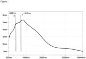
- Figure 1 shows the penetration depth of electromagnetic radiation into body tissue [mm] depending from the wavelength [nm]. It can be seen that the penetration depth is dependent from the wavelength.
- VIS visual
- NIR near-infrared
- VIS visual
- NIR near-infrared
- a body part irradiated with radiation will absorb electromagnetic energy resulting in a local increase of tissue temperature.
- IR radiation e.g. IR radiation in the wavelength range of about 5 ⁇ m to about 12 ⁇ m
- certain organic compounds present in bodily fluids i.e. physiological parameters, show absorption bands.
- This allows a quantitative or qualitative determination of glucose according to the above aspects of the present invention.
- Figure 2 shows relative absorption coefficients of certain compounds present in the human body depending from the wavelength in the range between 400 nm and 1100 nm.
- the wavelengths of about 600 nm and about 810 nm, at which radiation may be emitted into the body part, are specifically indicated.
- In the wavelength range of about 500 nm to about 1050 nm there is a relatively low absorption of water (H 2 O).
- Hb hemoglobin
- Hboxy oxyhemoglobin
- the skin pigment melamine shows an absorption coefficient which decreases with increasing wavelength.
- the radiation source (a) is adapted for emitting VIS/NIR radiation in the range of about 920 nm to about 960 nm, e.g. about 940 nm into a body part.
- This irradiation wavelength may be used alone or in combination with at least one further irradiation wavelength.
- glucose has an absorption band at a wavelength of 940 nm.
- irradiation at a wavelength of about 940 nm leads to a selective excitation of glucose molecules and may result in a stronger absorption of glucose molecules in the IR wavelength range, particularly in the wavelength range of about 5 ⁇ m to about 12 ⁇ m.
- the radiation source (a) is adapted for emitting VIS/NIR radiation in the range of about 920 nm to about 980 nm, e.g. about 940 nm into a body part of said subject
- the sensing unit (b) is further adapted for detecting VIS/NIR radiation having a wavelength of about 940 nm, where the intensity of the detected VIS/NIR radiation is dependent from the concentration of glucose.
- the measurement signal in the VIS/NIR wavelength range may be combined with the measurement signals in the IR range as described above, e.g. by means of a comparator.
- VIS/NIR irradiation occurs at a combination of at least 2 different wavelengths, particularly at a combination of a first wavelength of about 800 nm to about 820 nm, e.g. about 810 nm, and a second wavelength of about 920 nm to about 980 nm, e.g. about 940 nm.
- Figure 4 shows an embodiment of a system of the present invention.
- a body part (1) e.g. a fingertip
- the system which is adapted to irradiate an absorption area (2) within the body part (1).
- the system comprises a cover (3) which is at least partially made of a material, which is optically transparent.
- the cover is at least partially made of CaF 2 and/or BaF 2 or of a plastic material which is transparent in the IR wavelength range of about 5 ⁇ m to about 12 ⁇ m or a sub-range thereof, e.g. of about 8 ⁇ m to about 12 ⁇ m, and which is optionally transparent in the VIS/NIR wavelength range of about 400 nm to about 1500 nm or a sub-range thereof.
- Suitable IR-transparent plastic materials are e.g. the PolyIR plastic materials commercially available from Fresnel Technologies, Fort Worth, Texas, USA.
- the cover may have a thickness of about 0.2 mm to about 2 mm, particularly of about 0.5 mm to about 1.5 mm, more particularly about 1 mm.
- the system further comprises at least one sensor (4) which may be provided with a filter element (5) and optionally a lens element (not shown), which e.g. may be arranged between a sensor (4) and a filter element (5).
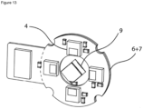
- the sensor (4) may be mounted on a circuit board (6).
- the system comprises at least one radiation source (9, 9a).
- the system may comprise a radiation source (9) located on the same side as the sensor (4) and/or a radiation source (9a) located on an opposite side of the body part (1) with regard to the sensor (4).
- a further sensor (4) may be provided without filter element (5) for monitoring the exact skin temperature of the subject.
- the system contains one or more sensors (4).
- the system comprises four different sensors (4).
- the sensor may be an optical detector, particularly an optical photovoltaic detector, e.g. an InAsSb-based detector, which may be used in combination with a lock-in amplifier, if desired.
- a photovoltaic detector e.g. an InAsSb-based detector has a rise time of only few nanoseconds and is particularly useful in a set-up wherein the body part is irradiated intermittently.
- the sensor may be heat detector, e.g. a thermopile or a bolometer. Suitable sensors include a photovoltaic detector (e.g.
- a sensor (4) may be provided with a filter element (5) capable of selectively transmitting radiation of a desired wavelength or wavelength range.
- the filter element may have narrow bandwidth, e.g. of about 50 to 100 nm, or a broader bandwidth, e.g. of about 400 nm or more.
- a filter may be made from germanium or other filter materials, which are optically transmissive for the respective wavelengths.
- a sensor may be provided with a lens element, e.g. a micro-lens capable of focusing the light falling onto the sensor.
- the sensor surface may be coated with a noble metal such as Au or Ag, particularly Au, in order to increase its sensitivity.
- a noble metal such as Au or Ag, particularly Au
- Such a coating which may be shaped as a Bundt baking-pan is described by Awad (Nature Scientific Reports 9:12197 (2019 )), the content of which is herein incorporated by reference.
- the senor is a miniaturized sensor having an area of about 1 mm 2 to about 10,000 mm 2 , e.g. of about 10 mm 2 to about 1,000 mm 2 .
- the sensor may be even more miniaturized, e.g. an ASIC (application-specific integrated circuit).
- At least two sensors are analyte-specific sensors, i.e. sensors which are adapted for detecting IR radiation having at least one wavelength or wavelength range where the intensity of the detected IR radiation is dependent from the concentration of glucose in the bodily fluid of said subject
- at least on sensor may be a reference sensor, i.e. a sensor which is adapted for detecting IR radiation having at least one wavelength or wavelength range where the intensity of the detected IR radiation is substantially independent from the concentration of glucose in the bodily fluid of said subject.
- the sensing unit (b) is adapted for detecting self-emitted IR radiation from the previously irradiated body part, i.e. IR radiation generated by the body heat of the subject without irradiation by an external IR source.
- the sensing unit (b) is adapted for detecting emitted IR radiation from an absorption area within the previously irradiated body part wherein the absorption area has a locally increased temperature and exhibits an increased emission of IR radiation in the wavelength range of about 5 ⁇ m to about 12 ⁇ m.
- At least one further sensor may be present, e.g. a sensor which (i) is adapted for detecting unspecific IR radiation, (ii) is adapted for detecting unspecific VIS/NIR radiation, (iii) is adapted for detecting VIS/NIR radiation having a wavelength, where the intensity of the detected VIS/NIR radiation is dependent from the concentration of the physiological parameter in the bodily fluid of said subject, and/or (iv) a temperature sensor for measuring the temperature of the body part.
- a sensor which (i) is adapted for detecting unspecific IR radiation, (ii) is adapted for detecting unspecific VIS/NIR radiation, (iii) is adapted for detecting VIS/NIR radiation having a wavelength, where the intensity of the detected VIS/NIR radiation is dependent from the concentration of the physiological parameter in the bodily fluid of said subject, and/or (iv) a temperature sensor for measuring the temperature of the body part.
- At least one further analyte-specific sensor may be present, i.e. a sensor which is adapted for detecting VIS/NIR radiation having at least one wavelength or wavelength range where the intensity of the detected VIS/NIR radiation is dependent from the concentration of the physiological parameter in the bodily fluid of said subject.
- at least one further sensor adapted for detecting VIR/NIR radiation having a wavelength of about 940 nm may be present.
- the device may comprise a circuit board (7) on which the light source (9) is mounted and an active and/or passive heat sink (8).
- the VIS/NIR radiation source (9, 9a, 9b) may be adapted for emitting collimated radiation, e.g. a laser-based light source, and/or adapted for emitting non-collimated radiation, e.g. an LED-based light source.
- the light source may be selected from an LED, a laser diode, a VCSEL (vertical-cavity surface-emitting laser) or a laser.
- a broadband VIS/NIR radiation emitter which may be adapted for emitting VIS/NIR radiation in the range of about 650 nm to about 950 nm, particularly in the range of about 750 nm to about 850 nm and more particularly in the range of about 780 nm to about 820 nm.
- Suitable VIS/NIR emitters are e.g. the OSLON products from Osram such as OSLON SFH 4763.
- the radiation source is adapted for emitting VIS/NIR radiation in the range of about 400 nm to about 1500 nm, particularly in the range of about 500 nm to about 1500 nm.
- the VIS/NIR radiation may be emitted continuously or intermittently throughout a predetermined time interval.
- the radiation source is adapted to cause a local increase in the temperature of the irradiated body part, e.g. a fingertip, and particularly a local increase in the temperature of the absorption area within the irradiated body part.
- the local increase in temperature may be in the range of between about 1°C to about 15°C, particularly about 2°C to about 10°C, and more particularly in the range of about 3°C to about 5°C.
- the locally increased temperature of the irradiated body part, e.g. a fingertip may be in temperature range up to about 45°C, up to about 40°C or up to about 37°C, for example in the temperature range between about 30°C to about 35°C or about 30°C to about 32°C.
- This local temperature increase results in an enhanced self-emission of IR radiation from the irradiated body part and particularly from the absorption area within the irradiated body part.
- the radiation source may be adapted for emitting radiation continuously at a power of about 10 mW to about 1 W, particularly for about 20 mW to about 500 mW, more particularly of about 50 mW to about 250 mW, and even more particularly of about 100 mW to about 200 mW, e.g. about 150 mW, for a time interval of about 0.1 to about 20 s, particularly of about 0.2 s to about 5 s, and more particularly of about 0.5 s to about 2 s, e.g. about 1 s.
- the radiation source may be adapted for emitting radiation intermittently at a power of about 10 mW to about 5 W, particularly of about 20 mW to about 1 W, and more particularly of about 50 mW to about 500 mW for a time interval of about 0.1 s to about 20 s, particularly of about 0.2 s to about 5 s, and more particularly of about 0.5 s to about 2 s.
- the radiation may be emitted intermittently with a pulse frequency of about 1 Hz to about 1 MHz.
- the radiation source may be adapted to emit VIS/NIR radiation at a plurality of different wavelengths, e.g. at 2, 3, 4, 5, 6, 7, 8 or even more different wavelengths.
- the radiation source may be multi LED chip.
- the use of a multi-wavelength radiation source allows adjusting a predetermined penetration depth of electromagnetic radiation into the tissue of the irradiated body part depending on specific characteristics of the body part, e.g. pigmentation, skin thickness, presence or absence of horny skin. As shown in Figure 1 , supra, the penetration depth into body tissue varies with the wavelength and the use of VIS/NIR radiation with different wavelengths or with combinations of different wavelengths can be adapted for each subject and/or each body part individually, if desired.
- the radiation source (a) is a multi-wavelength radiation source is adapted to emit VIS/NIR radiation at several different wavelengths or wavelength ranges, for example, between about 400 nm to about 1200 nm, more particularly between about 450 nm and about 900 nm, e.g. at least 2, 3 4, 6 or 8 wavelengths which may be selected from wavelengths at about 470 nm, about 520 nm, about 590 nm, about 650 nm, about 750 nm and about 810 nm.
- a single radiation source (9a) is provided on a side of the body part (1) which is opposite to a sensing unit comprising at least one sensor (4) provided with a filter (5) and a further sensor (4a) provided with a filter (5a).
- sensor (4a) is an optical sensor, e.g. a photodiode. It is adapted for a reference measurement of transmission radiation from radiation source (9a), e.g. for measuring radiation at a wavelength of about 600 nm and/or about 810 nm and/or about 940 nm.
- filter element (5a) may be a bandpass filter at about 600 nm and/or 810 nm and/or 940 nm.
- a radiation source (9b) is provided on a side of the body part (1), e.g. a fingertip, wherein direct access to an absorption area (2) within the body part (1) is provided through the skin of the body part without the radiation passing through a cover structure of the device and/or without passing through a horny structure on the body surface, e.g. a finger nail and/or horny skin.
- interference e.g. interference from the cover structure or from keratinic horny skin or nail material and optionally nail varnish can be reduced or eliminated.
- 2, 3, 4, 6 or 8 radiation sources may be provided at a position around the circumference of the body part (1), e.g. a fingertip. If a plurality of radiation sources is present, they are preferably adapted to emit radiation into a single absorption area (2) within the body part, which may be about 3 mm to about 5 mm below the body surface.
- a cover (3) is provided which is adapted for focusing IR radiation emitted from the body part to the at least one sensor (4) of the sensing unit.
- the cover (3) is made of a material, e.g. plastic, metal, metal oxide or composite material, which is substantially transparent for IR radiation in the wavelength range to be detected on the sensor, particularly for IR radiation in the wavelength range of about 5 ⁇ m to about 12 ⁇ m or a sub-range thereof, e.g. of about 8 ⁇ m to about 12 ⁇ m.
- Suitable materials are e.g. the PolyIR plastic materials, c.f.
- the cover (3) may comprise an IR Fresnel lens, i.e. a lens of large aperture and short focal length capable of efficiently focusing IR radiation passing therethrough, or an array comprising a plurality e.g. up to 10 or more IR Fresnel lenses.
- the array may comprise IR Fresnel micro-lenses, e.g. up to 100 or 1000 micro-lenses, which may have diameters in the range of about 50 nm to about 500 ⁇ m.
- the IR Fresnel lens may have a back focal length of about 3 mm to about 10 mm, e.g. about 5 mm and may be manufactured from an IR-transparent plastic.
- a suitable IR Fresnel lens which is optically transparent in the wavelength range of 8-14 ⁇ m is commercially available from Edmund Optics (product family no. 2042).
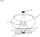
- Figure 7 shows a radiation source (9a) provided on the opposite side of the body part with regard to the position of the sensing unit, which comprises a sensor (4). It should be noted, however, that one or more radiation sources may also be arranged in a circumferential arrangement around the body part (1), e.g. as shown in Figure 6 . It should further be noted, that in this embodiment a plurality of different sensors may be present, e.g. as shown in Figures 4 and 5 .
- the system of the invention comprises a plurality of different glucose-specific sensors wherein a first sensor is adapted for detecting radiation at a first wavelength of about 9.2 ⁇ m and at least another first sensor is adapted for detecting IR radiation at a wavelength of about 9.2 ⁇ m and additionally at a wavelength of about 9.4 ⁇ m and a wavelength of about 9.6 ⁇ m.
- the sensing unit may comprise a plurality of reference sensors adapted for detecting reference radiation at different wavelengths or wavelength ranges.
- a reference sensor may be adapted for detecting radiation having a wavelength range between about 8.6 ⁇ m and about 9.0 ⁇ m.
- Another reference sensor is adapted for detecting radiation at a wavelength or wavelength range between about 9.8 ⁇ m and about 10.2 ⁇ m.
- a support (16) for the body part (1) e.g. a fingertip
- said support (16) comprises an opening adapted to receive a portion (15) of the body part (1).
- the support may comprise an annular structure with an opening, e.g. a substantially circular opening, in its center.
- the system is adapted for pressing the body part (1) onto the opening in the support (16) such that a portion (15) of the body part (1), e.g. a portion of the fingertip, is forced into the opening.
- the tissue including the blood vessels within portion (15) is compressed resulting in an enhanced amount of capillary blood within portion (15).
- the signal intensity and thus the sensitivity and/or accuracy of the measurement may be increased.
- the system of Figure 8 includes a cover (3) which may be formed as an IR Fresnel lens as described above in the context of Figure 7 . It should be noted, however, that other covers are also suitable.
- a radiation source (9a) is shown which is provided on the opposite side of the body part with regard to the position of the sensing unit, which comprises a sensor (4). It should be noted, however, that one or more radiation sources may also be arranged in a circumferential arrangement around the body part (1), e.g. as shown in Figure 6 . It should further be noted, that in this embodiment a plurality of different sensors may be present, e.g. as shown in Figures 4 and 5 .
- the absorption signal of glucose (24) has three different peaks at about 9.2 ⁇ m, at about 9.4 ⁇ m and about 9.6 ⁇ m.
- a first glucose-specific sensor may be adapted for measuring only the peak at 9.2 ⁇ m. Such a sensor would be adapted with a filter element capable of transmitting radiation only in a narrow range (22). Thus, the sensor is capable of selectively detecting radiation within this narrow range.
- a further glucose-specific sensor may be adapted for measuring radiation at a broader range between about 9.1 ⁇ m and about 9.7 ⁇ m, thereby encompassing the peaks at about 9.2 ⁇ m, 9.4 ⁇ m and 9.6 ⁇ m. This sensor may be adapted with a filter element capable of transmitting radiation in a broader range (21).
- Two reference sensors may be provided, wherein said reference sensors are provided with filter elements capable of transmission of radiation with a wavelength in the range of about 8.6 ⁇ m and about 9.0 ⁇ m, particularly of about 8.8 ⁇ m - 8.9 ⁇ m (20) and/or radiation with a wavelength in the range of about 9.8 ⁇ m and about 10.2 ⁇ m, particularly of about 9.9 ⁇ m - 10.1 ⁇ m (23), respectively.
- Parallel and separate measurements at a wavelength of about 9.2 ⁇ m on the one hand and at a wavelength range including the peak at 9.2 ⁇ m, but also at least one of the other peaks, particularly the peak at about 9.6 ⁇ m have a further advantage, since they allow determination whether the subject's blood contains ethanol. Since ethanol and other alcohols have an absorption band at a wavelength of about 9.6 ⁇ m, but not at a wavelength of about 9.2 ⁇ m, the ratio between the peak at 9.2 ⁇ m and 9.6 ⁇ m may be used to determine and optionally correct a disturbance caused by blood alcohol.
- a first glucose-specific sensor may be adapted for measuring only the peak at 9.6 ⁇ m.
- Such a sensor would be provided with a filter element capable of transmitting radiation only in a narrow range.
- a further glucose-specific sensor may be adapted for measuring radiation at a broader range between about 9.4 ⁇ m and about 9.6 ⁇ m, thereby encompassing the peaks at about 9.4 ⁇ m and about 9.6 ⁇ m and not encompassing the peak at 9.2 ⁇ m.
- This sensor may be provided with a filter element capable of transmitting radiation in a broader range.
- a reference sensor may be provided, which is provided with a filter element capable of transmission of radiation with a wavelength in the range of about 7.8 ⁇ m and about 8.2 ⁇ m, particularly of about 7.9 ⁇ m - 8.1 ⁇ m, optionally in combination with at least one further reference sensor, which is provided with a filter element capable of transmission of radiation with a wavelength in the range of about 8.8 ⁇ m - 9.2 ⁇ m and/or radiation with a wavelength of about 9.8 ⁇ m - 10.2 ⁇ m, respectively
- the system may comprise a sensor, which is adapted for a time-dependent detection of IR radiation having different wavelengths or wavelength ranges.
- the system may be provided with a sensor comprising a plurality of filters adapted for transmitting IR radiation having different wavelengths or wavelength ranges wherein said filters may be placed on a sensor during different stages of a measurement cycle thereby allowing detection of different wavelengths or wavelength ranges within a measurement cycle.
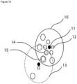
- a system is provided comprising a filter wheel (10) capable of rotating around an axis (11) and a shutter wheel (13) capable of rotating around an axis.
- the filter wheel and the shutter wheel are provided with illumination holes (15) through which light from the radiation source (not shown) may pass into the body part of the subject (not shown). Reflected light from the irradiated body part may pass through different holes (14) of the filter wheel (10) which may be provided with analyte-specific filter elements and/or reference filter elements as described above.
- the filter wheel's (10) and the shutter wheel's (13) position may be monitored with a magnet (12) in combination with a magnetic sensor.
- a sensor which is adapted for a time-dependent detection of IR radiation having different wavelengths or wavelength ranges may be a Fabry-Perot interferometer, e.g. a MEMS spectrometer for the desired IR wavelength range (cf. Tuohinieni et al., J. Micromech. Microeng. 22 (2012), 115004 ; Tuohinieni et al., J. Micromech. Microeng. 23 (2013), 075011 ).
- the system comprises a single sensor, which is adapted for a time-dependent detection of IR radiation having different wavelengths or wavelength ranges.
- This sensor may be provided with different filters, e.g. with a filter wheel, or be a Fabry-Perot interferometer as described above.
- the system of the present invention further comprises an analyzing unit (c) for the qualitative and/or quantitative determination of a physiological parameter based on the IR radiation detected in the sensing unit (b).
- the analyzing unit may comprise, for example, an A/D converter and a microcontroller.
- the analysis of the measured signal may be based on the intensity and/or the decay time.
- FIG. 11 A still further embodiment of the invention is shown in Figure 11 .
- the system of this embodiment is adapted for being permanently fixed to the subject's body.
- This system is particularly adapted for carrying out a plurality of measurements in predetermined time intervals.
- the system comprises a housing (30) and a strap (31) for fixing the housing around the body (33), e.g. a wrist or forearm.
- the system comprises a radiation source for emitting VIS/NIR light into an absorption area (34) of the body part (33) and sensors for detecting IR radiation emitted from the irradiated body part.
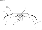
- FIG. 12 A still further embodiment of the invention is shown in Figure 12 .
- the system of this embodiment is adapted for being permanently fixed to the subject's body and particularly adapted for carrying out a plurality of measurements in predetermined time intervals.
- the system comprises a housing (30) and a strap (31) for fixing the housing around the body (33), e.g. a wrist or forearm.
- the system comprises a plurality of radiation sources, e.g. 2 radiation sources, for emitting VIS/NIR light into an absorption area (34) of the body part (33) and sensors for detecting IR radiation emitted from the irradiated body part.
- the light emitted from these sources may fall at angle, e.g. at an angle of about 30° to about 75° onto the surface of the body part (33).
- Figure 14 shows a heat map of a fingertip after irradiation with light of 810 nm for a time period of 2 s.
- Figure 15 is diagram showing the time-dependent thermal power output in addition to the self-emission of a fingertip during intermittent irradiation with light of 810 nm with a power of 2 mW and a frequency of 0.1 Hz.
- FIG 16a shows a block diagram of an embodiment of the sensing unit the present invention.
- a Region of Interest i.e. the skin tissue of a subject, particularly a human subject, is irradiated with a first light source emitting VIS/NIR radiation having a wavelength of 940 nm, a second light source emitting VIS/NIR radiation having a wavelength of about 810 nm and optionally a third light source emitting VIS/NIR radiation having a wavelength of about 600 nm.
- Radiation transmitted through the Region of Interest or reflected from the Region of Interest is analyzed by a sensing unit.
- the device comprises a temperature sensor.
- the sensing unit comprises a plurality of sensors, for example analyte-specific IR sensors (1) and (2) and reference sensors, e.g. IR sensor (4).
- an IR sensor (1) may be provided with a first optical filter, which is transmissive for a wavelength of about 9.2 ⁇ m and an IR sensor (2) may be provided with a second optical filter, which is transmissive for a wavelength range between about 9.2 ⁇ m and about 9.6 ⁇ m.
- a reference sensor (4) may be provided with a fourth optical filter which is transmissive for a wavelength or wavelength range between about 8.6 ⁇ m and about 9.0 ⁇ m and/or a wavelength or wavelength range between about 9.8 ⁇ m and about 10.2 ⁇ m.
- the sensing unit comprises an NIR sensor for detecting VIS/NIR radiation having a wavelength of about 940 ⁇ m where glucose has a strong absorption band.
- the NIR sensor is provided with a suitable optical filter, which is transmissive for this wavelength.
- the sensing unit may comprise a temperature sensor for measuring the temperature of the skin tissue in the Region of Interest.
- the respective sensors may be coupled to amplifiers (AMP) for first signal amplification. Signals from individual sensors may be referenced with signals from other sensors by means of a comparator, thereby improving the measurement accuracy and/or signal quality.
- the measurement signal from the NIR sensor at 940 nm may be referenced with the measurement signal from analyte-specific IR sensor (1).
- the measurement signal from the NIR sensor at 940 nm may be referenced with the measurement signals from analyte-specific IR sensor (1) and/or analyte-specific IR sensor (2) and/or reference IR sensor (4).
- the measured and optionally referenced signals are further amplified by a lock-in amplifier unit and transmitted to a microcontroller unit.
- a feedback control from the lock-in amplifier to the light sources may be provided.
- the signal and/or the result of internal algorithms may be transmitted to a display unit and/or another device, e.g. by a direct connection or via Bluetooth and/or WLAN.
- Figure 16b shows a block diagram of a further embodiment of the sensing unit of the present invention, which is similar to the sensing unit shown in Fig. 16a .
- a multi-wavelength light source e.g. a multi-wavelength LED comprising a plurality of individual diodes.
- the multi-wavelength light source may e.g. have a wavelength range from 400 nm to about 700 nm is provided and may be operated by the microcontroller unit.
- a temperature sensor coupled to an amplifier (AMP) is present. This temperature sensor may also be operated by the microcontroller unit.
- AMP amplifier
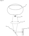
- the system may comprise a spectral or line sensor or spectral or line sensor array, typically a bolometer or thermopile array, which is adapted for detecting an IR spectrum within the wavelength range of interest, e.g. including the range of about 7 ⁇ m to about 12 ⁇ m, particularly including the range of about 8 ⁇ m to about 10 ⁇ m.
- An IR spectrum may be generated by passing the IR radiation from the irradiated body part through a spectral splitting or diffracting device and then to the sensor or sensor array. Such an embodiment is shown in Figure 17 . Emitted IR radiation (70) from the irradiated body part (71), e.g.
- a fingertip is optionally focused by a focusing element (72) adapted for focusing IR radiation, e.g. a lens or concave mirror element, and then passed to an spectral splitting or diffracting element (73), e.g. a prism or an transmissive or reflective optical grating, where the IR radiation is split according to its wavelength.
- an spectral sensor or line sensor or sensor array typically a bolometer or thermopile array, where an IR spectrum in the wavelength range of interest, e.g. between 8 ⁇ m and about 20 ⁇ m including analyte-specific wavelengths or wavelength ranges and reference wavelengths or wavelength ranges, e.g. as described above, is detected.
- the amount of the physiological parameter of interest e.g. glucose may be determined by spectral analysis according to the relative intensities of predetermined analyte-specific and reference wavelengths.
- the system and the method of the invention allow qualitative and/or quantitative determination of the physiological parameter to be measured, the qualitative and/or quantitative determination of glucose in blood.
- the concentration of the physiological parameter, the concentration of glucose in blood is quantitatively determined.
- the alteration rate of the measured amount of the physiological parameter, glucose is determined.
- a non-quantitative measurement e.g. a relative measurement of the alteration of the analyte amount per time unit, i.e. the increase of the analyte amount or the decrease of the analyte amount per time unit.
- the alteration of the analyte amount into a single direction i.e. increase or decrease, exceeds a predetermined level and/or time period, the system will provide an alert.
- This embodiment is particularly useful for systems as shown in Figure 11 and Figure 12 , which may be permanently fixed at the body of the subject, e.g. around the wrist, forearm or upper arm. This embodiment may be adapted for steady glucose level monitoring.
- the system of the invention is adapted for performing both non-quantitative measurements and quantitative measurements.
- the system may be adapted for performing non-quantitative measurements, e.g. qualitatively measuring the alteration, e.g. the increase or decrease, of the analyte amount over time during standard operation.
- Non-quantitative measurements may e.g. be performed as continuous and/or intermittent monitoring measurements, as required.
- the system is adapted to switch to a quantitative measurement in order to provide more detailed information.
- a system adapted to be permanently fixed to the body e.g. to an arm wrist, or to an ankle, may be used. Specific embodiments of such systems are shown in Figure 11 and Figure 12 .
- the system is adapted to perform non-quantitative measurements, e.g. continuous and/or intermittent monitoring measurements, and quantitative measurements on several different body parts.
- the system may be adapted to perform non-quantitative measurements on a first body part, e.g. a body part to which the system may be permanently fixed, such as an arm wrist or an ankle, and to perform quantitative measurements on a second body part, e.g. a body part where capillary vessels are more accessible, such as an earlobe or a fingertip.
- the system is removed from the first body part and brought into contact, particularly into direct contact with the second body part.
- the system may be removed therefrom and brought again into contact with the first body part, e.g. by fixing the system to the first body part.
- the first body part is an arm wrist and/or the second body part is a fingertip.
- a still further aspect of the invention is a non-invasive system for determining glucose in blood, which allows identification and optional correction of disturbances caused by blood alcohol
- a sensing unit for detecting emitted IR radiation from a body part of said subject in the range of about 5 ⁇ m to about 12 ⁇ m, wherein said sensing unit is adapted for (i) detecting IR radiation at a wavelength of about 9.2 ⁇ m and separately therefrom for detecting IR radiation at a wavelength range encompassing the wavelength of about 9.2 ⁇ m, about 9.4 ⁇ m and about 9.6 ⁇ m, and an analyzing unit for the separate determination of glucose from the above sensing units.
- Still a further aspect of the invention is a method for non-invasively determining glucose in blood of a subject using this system.
- Still a further aspect of the present disclosure is the use of an InAsSb sensor, optionally in combination with a lock-in amplifier for the measure of IR radiation emitted from a body part.
- Still a further aspect of the present disclosure is a system and method for the non-quantitative measurement of glucose involving a plurality of measurements during a predetermined time interval and determining an alteration of the measurement signal indicating an alteration of the amount of analyte and providing an alter if the alteration of the glucose amount to one direction, i.e. increase or decrease, exceeds a certain level in a predetermined time period.
- This system and method may be adapted for steady glucose level monitoring.
Landscapes
- Health & Medical Sciences (AREA)
- Life Sciences & Earth Sciences (AREA)
- Physics & Mathematics (AREA)
- Heart & Thoracic Surgery (AREA)
- Molecular Biology (AREA)
- Pathology (AREA)
- Engineering & Computer Science (AREA)
- Biomedical Technology (AREA)
- Veterinary Medicine (AREA)
- Medical Informatics (AREA)
- Biophysics (AREA)
- Surgery (AREA)
- Animal Behavior & Ethology (AREA)
- General Health & Medical Sciences (AREA)
- Public Health (AREA)
- Optics & Photonics (AREA)
- Spectroscopy & Molecular Physics (AREA)
- Emergency Medicine (AREA)
- Measurement Of The Respiration, Hearing Ability, Form, And Blood Characteristics Of Living Organisms (AREA)
Claims (13)
- Un système non invasif pour déterminer le glucose dans un fluide corporel d'un sujet comprenant :(a) une source de rayonnement (9, 9a, 9b) adaptée pour émettre un rayonnement visible (VIS)/infrarouge proche (NIR) dans la plage de 400 nm à 1500 nm ou de 500 nm à 1500 nm dans une partie du corps (1) dudit sujet,dans lequel la partie du corps (1) est particulièrement choisie parmi le bout d'un doigt, un lobe d'oreille, un poignet, un avant-bras et un bras,et dans lequel la partie du corps irradiée absorbe l'énergie électromagnétique émise, ce qui entraîne une augmentation locale de la température du tissu et une augmentation de l'émission de rayonnement IR dans la plage de longueurs d'onde de 5 µm à 12 µm,(b) une unité de détection adaptée pour détecter le rayonnement IR émis par la partie du corps précédemment irradiée dudit sujet dans la plage de 5 µm à 12 µm, dans lequel ladite unité de détection est adaptée pour (i) détecter le rayonnement IR ayant au moins une première longueur d'onde ou une première plage de longueurs d'onde où l'intensité du rayonnement détecté dépend de la concentration de glucose dans le fluide corporel dudit sujet, et pour (ii) détecter un rayonnement IR ayant au moins une deuxième longueur d'onde ou une deuxième plage de longueurs d'onde où l'intensité du rayonnement IR détecté est substantiellement indépendante de la concentration de glucose dans le fluide corporel dudit sujet,
dans lequel au moins ladite première longueur d'onde ou ladite première plage de longueurs d'onde et au moins ladite deuxième longueur d'onde ou ladite deuxième plage de longueurs d'onde se situent dans la plage de longueurs d'onde de 5 µm à 12 µm, et(c) une unité d'analyse configurée pour effectuer la détermination qualitative et/ou quantitative du glucose sur la base du rayonnement IR détecté dans l'unité de détection (b) dans ladite moins une première longueur d'onde ou ladite première plage de longueurs d'onde et dans ladite au moins une deuxième longueur d'onde ou une deuxième plage de longueurs d'onde, dans lequel l'unité de détection (b) comprend au moins deux premiers capteurs (4),dans lequel chacun des au moins deux capteurs (4) est adapté pour détecter un rayonnement IR ayant au moins une première longueur d'onde ou une première plage de longueurs d'onde où l'intensité du rayonnement IR détecté dépend de la concentration de glucose dans le fluide corporel dudit sujet, etdans lequel au moins un premier capteur (4) est adapté pour détecter un rayonnement IR ayant une longueur d'onde d'environ 9,2 µm et au moins un autre premier capteur (4) est adapté pour détecter un rayonnement IR ayant une plage de longueurs d'onde comprise entre 9,2 µm et 9,6 µm qui comprend la première longueur d'onde d'environ 9,2 µm et comprend en outre une longueur d'onde d'environ 9,4 µm et d'environ 9,6 µm,
etdans lequel l'unité de détection comprend au moins un deuxième capteur (4), qui est adapté pour détecter un rayonnement IR ayant au moins une deuxième longueur d'onde ou une deuxième plage de longueurs d'onde où l'intensité du rayonnement IR détecté est sensiblement indépendante de la concentration de glucose dans le fluide corporel dudit sujet. - Le système selon la revendication 1, qui ne comprend pas de source de rayonnement externe adaptée pour émettre un rayonnement IR dans la plage de longueurs d'onde de 5 µm à 12 µm.
- Le système selon la revendication 1 ou 2, dans lequel le fluide corporel est du sang.
- Le système selon l'une quelconque des revendications précédentes, dans lequel la source de rayonnement (a) est adaptée pour émettre un rayonnement VIS/NIR dans la plage de 550 nm à 1200 nm, en particulier dans la plage de 800 nm à 820 nm, par exemple d'environ 810 nm, et/ou dans la plage de 590 nm à 610 nm, par exemple d'environ 600 nm, et/ou dans la plage de 920 nm à 980 nm, par exemple d'environ 940 nm.
- Le système selon l'une quelconque des revendications précédentes, dans lequel la source de rayonnement (a) est une LED, une diode laser, un vcsel (laser à cavité verticale émettant par la surface) ou un laser, et/ou dans lequel la source de rayonnement (a) est une source de rayonnement à longueurs d'onde multiples.
- Le système selon l'une quelconque des revendications précédentes, comprenant en outre au moins un troisième capteur,
dans lequel ledit au moins un troisième capteur (i) est adapté pour détecter un rayonnement IR non spécifique (ii), est adapté pour détecter un rayonnement VIS/NIR non spécifique (iii), est adapté pour détecter un rayonnement VIS/NIR ayant une longueur d'onde, où l'intensité du rayonnement VIS/NIR détecté dépend de la concentration du paramètre physiologique dans le fluide corporel dudit sujet, et/ou (iv) est un capteur de température adapté pour mesurer la température de la partie du corps. - Le système selon l'une quelconque des revendications précédentes comprenant au moins deux deuxièmes capteurs différents, qui sont adaptés pour détecter un rayonnement IR ayant au moins deux longueurs d'onde ou plages de longueurs d'onde différentes,dans lequel le système est particulièrement adapté pour déterminer le glucose dans le sang,dans lequel un deuxième capteur est adapté pour détecter un rayonnement IR ayant une longueur d'onde ou une plage de longueurs d'onde comprise entre 8,6 µm et 9,0 µm et un autre deuxième capteur est adapté pour détecter un rayonnement IR ayant une longueur d'onde ou une plage de longueurs d'onde comprise entre 9,8 µm et 10,2 µm.
- Le système selon l'une des revendications précédentes, dans lequel l'unité de détection (b) comprend au moins un capteur adapté pour détecter séparément et en fonction du temps un rayonnement IR ayant différentes longueurs d'onde ou plages de longueurs d'onde,dans lequel, dans au moins un premier intervalle de temps, le capteur est adapté pour détecter un rayonnement IR ayant au moins une longueur d'onde ou une plage de longueurs d'onde où l'intensité du rayonnement IR détecté dépend de la concentration de glucose dans le fluide corporel dudit sujet, etdans lequel, dans au moins un deuxième intervalle de temps, le capteur est adapté pour détecter un rayonnement IR ayant au moins une longueur d'onde ou une plage de longueurs d'onde où l'intensité du rayonnement IR détecté est substantiellement indépendante de la concentration de glucose dans le fluide corporel dudit sujet.
- Le système selon l'une quelconque des revendications précédentes,
dans lequel l'unité de détection (b) comprend au moins un capteur qui est un détecteur optique, en particulier un détecteur optique photovoltaïque, plus particulièrement un détecteur à base d'InAsSb. - Le système selon l'une quelconque des revendications précédentes comprenant en outre un couvercle, dans lequel ledit couvercle est au moins partiellement constitué d'un matériau optiquement transparent pour le rayonnement IR/VIS émis par la source de rayonnement (a) et pour le rayonnement IR détecté par l'unité de détection (b),dans lequel le couvercle est au moins partiellement constitué de CaF2 et/ou de BaF2 et/ou d'un matériau plastique qui est transparent pour le rayonnement IR et éventuellement transparent pour le rayonnement VIS/NIR,dans lequel le matériau optiquement transparent du couvercle a une épaisseur d'environ 0,2 mm à environ 2 mm, en particulier d'environ 0,5 mm à environ 1,5 mm, plus particulièrement d'environ 1 mm, et/ou comprenant en outre un couvercle qui concentre le rayonnement IR de la partie du corps vers l'unité de détection (b), en particulier vers ledit au moins un capteur de l'unité de détection (b), en particulier dans lequel le couvercle comprend une lentille de Fresnel IR ou un réseau comprenant une pluralité de lentilles de Fresnel IR.
- Une méthode de détermination non invasive du glucose dans un fluide corporel d'un sujet, comprenant les étapes suivantes :(a) irradier une partie du corps (1) dudit sujet avec un rayonnement visible (VIS)/infrarouge proche (NIR) dans la plage de longueurs d'onde de 400 nm à 1500 nm, ou de 500 nm à 1500 nm, dans lequel la partie du corps irradiée (1) absorbe l'énergie électromagnétique émise, ce qui entraîne une augmentation locale de la température des tissus et une émission augmentée de rayonnement IR dans la plage de longueurs d'onde de 5 µm à 12 µm,(b) détecter le rayonnement IR émis par la partie du corps dudit sujet préalablement irradiée dans la plage de longueurs d'onde de 5 µm à 12 µm,comprenant séparément (i) la détection du rayonnement IR ayant au moins deux longueurs d'onde ou plages de longueurs d'onde où l'intensité du rayonnement IR détecté dépend de la concentration de glucose dans le fluide corporel dudit sujet, comprenant la détection du rayonnement IR ayant une longueur d'onde d'environ 9,2 µm et la détection d'un rayonnement IR ayant une plage de longueurs d'onde comprise entre 9,2 µm et 9,6 µm qui comprend la longueur d'onde d'environ 9,2 µm et comprend en outre une longueur d'onde d'environ 9,4 µm et d'environ 9,6 µm, et(ii) détecter le rayonnement IR ayant au moins une longueur d'onde ou une plage de longueurs d'onde où l'intensité du rayonnement IR détecté est substantiellement indépendante de la concentration de glucose dans le fluide corporel dudit sujet, et (c) analyser le rayonnement IR détecté pour la détermination qualitative et/ou quantitative du glucose,en particulier dans lequel la concentration de glucose est déterminée quantitativement, et/ou dans laquelle le taux d'altération de la quantité de glucose est déterminé, en particulier de manière non quantitative.
- La méthode selon la revendication 11, dans laquelle la partie du corps n'est pas irradiée par une source externe de rayonnement IR dans la plage de longueurs d'onde de 5 µm à 12 µm.
- La méthode selon la revendication 11 ou 12, dans laquelle le fluide corporel est du sang.
Priority Applications (1)
| Application Number | Priority Date | Filing Date | Title |
|---|---|---|---|
| EP25158478.5A EP4578377A3 (fr) | 2019-08-16 | 2020-08-14 | Système et procédé de détection miniaturisée active |
Applications Claiming Priority (6)
| Application Number | Priority Date | Filing Date | Title |
|---|---|---|---|
| US201962887767P | 2019-08-16 | 2019-08-16 | |
| EP19192138.6A EP3777680A1 (fr) | 2019-08-16 | 2019-08-16 | Système et méthode de détection |
| EP19195939 | 2019-09-06 | ||
| EP19218195 | 2019-12-19 | ||
| EP20158808 | 2020-02-21 | ||
| PCT/EP2020/072885 WO2021032629A1 (fr) | 2019-08-16 | 2020-08-14 | Système et procédé de détection actif miniaturisé |
Related Child Applications (1)
| Application Number | Title | Priority Date | Filing Date |
|---|---|---|---|
| EP25158478.5A Division EP4578377A3 (fr) | 2019-08-16 | 2020-08-14 | Système et procédé de détection miniaturisée active |
Publications (3)
| Publication Number | Publication Date |
|---|---|
| EP4013304A1 EP4013304A1 (fr) | 2022-06-22 |
| EP4013304B1 true EP4013304B1 (fr) | 2025-02-19 |
| EP4013304C0 EP4013304C0 (fr) | 2025-02-19 |
Family
ID=74660203
Family Applications (2)
| Application Number | Title | Priority Date | Filing Date |
|---|---|---|---|
| EP25158478.5A Pending EP4578377A3 (fr) | 2019-08-16 | 2020-08-14 | Système et procédé de détection miniaturisée active |
| EP20754263.0A Active EP4013304B1 (fr) | 2019-08-16 | 2020-08-14 | Système et méthode de détection |
Family Applications Before (1)
| Application Number | Title | Priority Date | Filing Date |
|---|---|---|---|
| EP25158478.5A Pending EP4578377A3 (fr) | 2019-08-16 | 2020-08-14 | Système et procédé de détection miniaturisée active |
Country Status (8)
| Country | Link |
|---|---|
| US (1) | US20220287600A1 (fr) |
| EP (2) | EP4578377A3 (fr) |
| JP (2) | JP7653975B2 (fr) |
| KR (1) | KR20220059487A (fr) |
| CN (1) | CN114449942B (fr) |
| AU (1) | AU2020331683B2 (fr) |
| CA (1) | CA3150802A1 (fr) |
| WO (1) | WO2021032629A1 (fr) |
Families Citing this family (4)
| Publication number | Priority date | Publication date | Assignee | Title |
|---|---|---|---|---|
| KR20220059487A (ko) * | 2019-08-16 | 2022-05-10 | 글루코마트 게엠베하 | 능동형 소형 감지 시스템 및 방법 |
| EP4037560B1 (fr) * | 2019-09-30 | 2025-03-26 | Gluco Tera Tech Ag | Détermination non invasive des glucose |
| KR20250154397A (ko) | 2023-01-31 | 2025-10-28 | 글루코마트 게엠베하 | 고도로 통합된 포도당 센서 디바이스 |
| GB202409812D0 (en) * | 2024-07-05 | 2024-08-21 | Univ Court Univ Of Glasgow | Blood glucose level sensing device |
Citations (1)
| Publication number | Priority date | Publication date | Assignee | Title |
|---|---|---|---|---|
| US5900632A (en) * | 1997-03-12 | 1999-05-04 | Optiscan Biomedical Corporation | Subsurface thermal gradient spectrometry |
Family Cites Families (30)
| Publication number | Priority date | Publication date | Assignee | Title |
|---|---|---|---|---|
| US5222496A (en) * | 1990-02-02 | 1993-06-29 | Angiomedics Ii, Inc. | Infrared glucose sensor |
| US5079421A (en) * | 1990-04-19 | 1992-01-07 | Inomet, Inc. | Invasive FTIR blood constituent testing |
| US5313941A (en) * | 1993-01-28 | 1994-05-24 | Braig James R | Noninvasive pulsed infrared spectrophotometer |
| US5553613A (en) * | 1994-08-17 | 1996-09-10 | Pfizer Inc. | Non invasive blood analyte sensor |
| US6025597A (en) * | 1995-10-17 | 2000-02-15 | Optiscan Biomedical Corporation | Non-invasive infrared absorption spectrometer for measuring glucose or other constituents in a human or other body |
| US6161028A (en) * | 1999-03-10 | 2000-12-12 | Optiscan Biomedical Corporation | Method for determining analyte concentration using periodic temperature modulation and phase detection |
| US6285448B1 (en) * | 1997-05-05 | 2001-09-04 | J. Todd Kuenstner | Clinical analyte determination by infrared spectroscopy |
| EP1037553B1 (fr) * | 1997-11-12 | 2007-01-24 | Lightouch Medical, Inc. | Procede de mesure non invasive d'un analyte |
| DE69929710T2 (de) * | 1998-12-15 | 2006-09-21 | Citizen Watch Co., Ltd. | Klinisches strahlungsthermometer |
| US6198949B1 (en) * | 1999-03-10 | 2001-03-06 | Optiscan Biomedical Corporation | Solid-state non-invasive infrared absorption spectrometer for the generation and capture of thermal gradient spectra from living tissue |
| US6486474B1 (en) * | 1999-08-13 | 2002-11-26 | Regents Of The University Of Minnesota | Infrared spectrometer for the measurement of isotopic ratios |
| IL136291A0 (en) * | 2000-05-22 | 2001-05-20 | Yatsiv Shaul | Infrared spectral sources |
| AU2002249985B2 (en) * | 2001-01-26 | 2005-11-17 | Sensys Medical, Inc. | Noninvasive measurement of glucose through the optical properties of tissue |
| WO2005074550A2 (fr) * | 2004-01-30 | 2005-08-18 | 3Wave Optics, Llc | Systeme de mesure non effractive de composant sanguin |
| GB0501826D0 (en) * | 2005-01-28 | 2005-03-09 | Melys Diagnostics Ltd | Apparatus for measurement of analyte concentration |
| CN101400300A (zh) * | 2006-03-10 | 2009-04-01 | 松下电器产业株式会社 | 生物体成分浓度测定装置 |
| US7684841B2 (en) * | 2006-03-10 | 2010-03-23 | Panasonic Corporation | Living body ingredient concentration measuring instrument |
| US20110009720A1 (en) * | 2006-11-02 | 2011-01-13 | Kislaya Kunjan | Continuous whole blood glucose monitor |
| CN101917899B (zh) * | 2007-11-05 | 2014-03-12 | 生物传感器公司 | 用于测定分析物浓度的光学传感器 |
| US8401604B2 (en) * | 2008-04-11 | 2013-03-19 | Glucovista, Llc | Apparatus and methods for non-invasive measurement of a substance within a body |
| US20110004080A1 (en) * | 2008-04-11 | 2011-01-06 | Glucovista, Llc | Method for non-invasive analysis of a substance concentration within a body |
| GB201011459D0 (en) * | 2010-07-07 | 2010-08-25 | Melys Diagnostics Ltd | Optical element, assembly and method for determining analyte concentration |
| US9119528B2 (en) * | 2012-10-30 | 2015-09-01 | Dexcom, Inc. | Systems and methods for providing sensitive and specific alarms |
| DE102013010611A1 (de) * | 2013-06-25 | 2015-01-08 | Sms Swiss Medical Sensor Ag | Messvorrichtung und Messverfahren zum Messen von Rohdaten zur Bestimmung eines Blutparameters, insbesondere zur nichtinvasiven Bestimmung der D-Glucose-Konzentration |
| EP3175783B1 (fr) * | 2014-01-07 | 2022-01-19 | Opsolution GmbH | Dispositif et procédé de détermination d'une concentration dans un échantillon |
| JP2016067394A (ja) * | 2014-09-26 | 2016-05-09 | セイコーエプソン株式会社 | 成分計測装置及び成分計測方法 |
| RU2574571C1 (ru) * | 2014-12-22 | 2016-02-10 | Эдвард Владимирович Крыжановский | Способ неинвазивного определения концентрации глюкозы в крови |
| WO2018122319A1 (fr) * | 2016-12-30 | 2018-07-05 | Swiss Spectral Ag | Dispositif et procédé de détermination non-invasive d'analytes |
| EP3443887A1 (fr) * | 2017-08-18 | 2019-02-20 | Swiss Spectral AG | Dispositif et procédé de détermination non invasive d'analytes sans source de rayonnement externe |
| KR20220059487A (ko) * | 2019-08-16 | 2022-05-10 | 글루코마트 게엠베하 | 능동형 소형 감지 시스템 및 방법 |
-
2020
- 2020-08-14 KR KR1020227008813A patent/KR20220059487A/ko active Pending
- 2020-08-14 EP EP25158478.5A patent/EP4578377A3/fr active Pending
- 2020-08-14 CN CN202080064848.4A patent/CN114449942B/zh active Active
- 2020-08-14 WO PCT/EP2020/072885 patent/WO2021032629A1/fr not_active Ceased
- 2020-08-14 JP JP2022510082A patent/JP7653975B2/ja active Active
- 2020-08-14 AU AU2020331683A patent/AU2020331683B2/en active Active
- 2020-08-14 EP EP20754263.0A patent/EP4013304B1/fr active Active
- 2020-08-14 CA CA3150802A patent/CA3150802A1/fr active Pending
- 2020-08-14 US US17/635,650 patent/US20220287600A1/en active Pending
-
2025
- 2025-03-18 JP JP2025044150A patent/JP2025090832A/ja active Pending
Patent Citations (1)
| Publication number | Priority date | Publication date | Assignee | Title |
|---|---|---|---|---|
| US5900632A (en) * | 1997-03-12 | 1999-05-04 | Optiscan Biomedical Corporation | Subsurface thermal gradient spectrometry |
Also Published As
| Publication number | Publication date |
|---|---|
| EP4578377A3 (fr) | 2025-08-20 |
| WO2021032629A1 (fr) | 2021-02-25 |
| JP2025090832A (ja) | 2025-06-17 |
| JP2022551381A (ja) | 2022-12-09 |
| EP4578377A2 (fr) | 2025-07-02 |
| JP7653975B2 (ja) | 2025-03-31 |
| AU2020331683A1 (en) | 2022-03-31 |
| CN114449942A (zh) | 2022-05-06 |
| EP4013304C0 (fr) | 2025-02-19 |
| AU2020331683B2 (en) | 2025-08-14 |
| CA3150802A1 (fr) | 2021-02-25 |
| CN114449942B (zh) | 2026-03-20 |
| EP4013304A1 (fr) | 2022-06-22 |
| US20220287600A1 (en) | 2022-09-15 |
| KR20220059487A (ko) | 2022-05-10 |
Similar Documents
| Publication | Publication Date | Title |
|---|---|---|
| US12066378B2 (en) | Device and method for analyzing a material | |
| EP4013304B1 (fr) | Système et méthode de détection | |
| US5460177A (en) | Method for non-invasive measurement of concentration of analytes in blood using continuous spectrum radiation | |
| JP3875798B2 (ja) | 血中成分濃度の無血測定装置の作動方法及び無血測定装置 | |
| WO2005012553A2 (fr) | Sonde optique in vivo de concentration d'analytes dans la matrice sterile sous l'ongle humain | |
| WO2003076883B1 (fr) | Appareil compact de mesure non effractive du glucose par spectroscopie proche infrarouge | |
| WO2005074550A2 (fr) | Systeme de mesure non effractive de composant sanguin | |
| EP0948284A1 (fr) | Controle d'analysats de tissus par rayonnement infrarouge | |
| WO1997019341A1 (fr) | Mesure par voie transcutanee de substance presente dans les tissus ou les fluides corporels | |
| WO2012136982A1 (fr) | Dispositif et procédé pour la détection d'analytes sanguins | |
| US12364416B2 (en) | Portable device and method for non-invasive blood glucose level estimation | |
| JP2009539459A (ja) | 専用特殊照明分光法 | |
| US20240099611A1 (en) | Active Miniaturized Sensing System | |
| KR100612861B1 (ko) | 체액 성분농도 측정용 가변파장 발생방법 및 장치 | |
| EP3777680A1 (fr) | Système et méthode de détection | |
| EP4658153A1 (fr) | Dispositif de capteur de glucose hautement intégré | |
| WO1996013201A1 (fr) | Procede non invasif de mesure de la concentration d'un analyte dans le sang | |
| HK1253844A1 (en) | Device and method for analysing a material |
Legal Events
| Date | Code | Title | Description |
|---|---|---|---|
| STAA | Information on the status of an ep patent application or granted ep patent |
Free format text: STATUS: UNKNOWN |
|
| STAA | Information on the status of an ep patent application or granted ep patent |
Free format text: STATUS: THE INTERNATIONAL PUBLICATION HAS BEEN MADE |
|
| PUAI | Public reference made under article 153(3) epc to a published international application that has entered the european phase |
Free format text: ORIGINAL CODE: 0009012 |
|
| STAA | Information on the status of an ep patent application or granted ep patent |
Free format text: STATUS: REQUEST FOR EXAMINATION WAS MADE |
|
| 17P | Request for examination filed |
Effective date: 20220316 |
|
| AK | Designated contracting states |
Kind code of ref document: A1 Designated state(s): AL AT BE BG CH CY CZ DE DK EE ES FI FR GB GR HR HU IE IS IT LI LT LU LV MC MK MT NL NO PL PT RO RS SE SI SK SM TR |
|
| DAV | Request for validation of the european patent (deleted) | ||
| DAX | Request for extension of the european patent (deleted) | ||
| STAA | Information on the status of an ep patent application or granted ep patent |
Free format text: STATUS: EXAMINATION IS IN PROGRESS |
|
| 17Q | First examination report despatched |
Effective date: 20240111 |
|
| GRAP | Despatch of communication of intention to grant a patent |
Free format text: ORIGINAL CODE: EPIDOSNIGR1 |
|
| STAA | Information on the status of an ep patent application or granted ep patent |
Free format text: STATUS: GRANT OF PATENT IS INTENDED |
|
| INTG | Intention to grant announced |
Effective date: 20240711 |
|
| GRAJ | Information related to disapproval of communication of intention to grant by the applicant or resumption of examination proceedings by the epo deleted |
Free format text: ORIGINAL CODE: EPIDOSDIGR1 |
|
| STAA | Information on the status of an ep patent application or granted ep patent |
Free format text: STATUS: EXAMINATION IS IN PROGRESS |
|
| INTC | Intention to grant announced (deleted) | ||
| GRAP | Despatch of communication of intention to grant a patent |
Free format text: ORIGINAL CODE: EPIDOSNIGR1 |
|
| STAA | Information on the status of an ep patent application or granted ep patent |
Free format text: STATUS: GRANT OF PATENT IS INTENDED |
|
| INTG | Intention to grant announced |
Effective date: 20240918 |
|
| GRAS | Grant fee paid |
Free format text: ORIGINAL CODE: EPIDOSNIGR3 |
|
| GRAA | (expected) grant |
Free format text: ORIGINAL CODE: 0009210 |
|
| STAA | Information on the status of an ep patent application or granted ep patent |
Free format text: STATUS: THE PATENT HAS BEEN GRANTED |
|
| AK | Designated contracting states |
Kind code of ref document: B1 Designated state(s): AL AT BE BG CH CY CZ DE DK EE ES FI FR GB GR HR HU IE IS IT LI LT LU LV MC MK MT NL NO PL PT RO RS SE SI SK SM TR |
|
| REG | Reference to a national code |
Ref country code: GB Ref legal event code: FG4D |
|
| REG | Reference to a national code |
Ref country code: CH Ref legal event code: EP |
|
| REG | Reference to a national code |
Ref country code: IE Ref legal event code: FG4D |
|
| REG | Reference to a national code |
Ref country code: DE Ref legal event code: R096 Ref document number: 602020046328 Country of ref document: DE |
|
| U01 | Request for unitary effect filed |
Effective date: 20250318 |
|
| U07 | Unitary effect registered |
Designated state(s): AT BE BG DE DK EE FI FR IT LT LU LV MT NL PT RO SE SI Effective date: 20250324 |
|
| PG25 | Lapsed in a contracting state [announced via postgrant information from national office to epo] |
Ref country code: RS Free format text: LAPSE BECAUSE OF FAILURE TO SUBMIT A TRANSLATION OF THE DESCRIPTION OR TO PAY THE FEE WITHIN THE PRESCRIBED TIME-LIMIT Effective date: 20250519 |
|
| PG25 | Lapsed in a contracting state [announced via postgrant information from national office to epo] |
Ref country code: PL Free format text: LAPSE BECAUSE OF FAILURE TO SUBMIT A TRANSLATION OF THE DESCRIPTION OR TO PAY THE FEE WITHIN THE PRESCRIBED TIME-LIMIT Effective date: 20250219 |
|
| PG25 | Lapsed in a contracting state [announced via postgrant information from national office to epo] |
Ref country code: ES Free format text: LAPSE BECAUSE OF FAILURE TO SUBMIT A TRANSLATION OF THE DESCRIPTION OR TO PAY THE FEE WITHIN THE PRESCRIBED TIME-LIMIT Effective date: 20250219 |
|
| PG25 | Lapsed in a contracting state [announced via postgrant information from national office to epo] |
Ref country code: NO Free format text: LAPSE BECAUSE OF FAILURE TO SUBMIT A TRANSLATION OF THE DESCRIPTION OR TO PAY THE FEE WITHIN THE PRESCRIBED TIME-LIMIT Effective date: 20250519 Ref country code: IS Free format text: LAPSE BECAUSE OF FAILURE TO SUBMIT A TRANSLATION OF THE DESCRIPTION OR TO PAY THE FEE WITHIN THE PRESCRIBED TIME-LIMIT Effective date: 20250619 |
|
| PG25 | Lapsed in a contracting state [announced via postgrant information from national office to epo] |
Ref country code: HR Free format text: LAPSE BECAUSE OF FAILURE TO SUBMIT A TRANSLATION OF THE DESCRIPTION OR TO PAY THE FEE WITHIN THE PRESCRIBED TIME-LIMIT Effective date: 20250219 |
|
| PG25 | Lapsed in a contracting state [announced via postgrant information from national office to epo] |
Ref country code: GR Free format text: LAPSE BECAUSE OF FAILURE TO SUBMIT A TRANSLATION OF THE DESCRIPTION OR TO PAY THE FEE WITHIN THE PRESCRIBED TIME-LIMIT Effective date: 20250520 |
|
| PG25 | Lapsed in a contracting state [announced via postgrant information from national office to epo] |
Ref country code: SM Free format text: LAPSE BECAUSE OF FAILURE TO SUBMIT A TRANSLATION OF THE DESCRIPTION OR TO PAY THE FEE WITHIN THE PRESCRIBED TIME-LIMIT Effective date: 20250219 |
|
| PG25 | Lapsed in a contracting state [announced via postgrant information from national office to epo] |
Ref country code: CZ Free format text: LAPSE BECAUSE OF FAILURE TO SUBMIT A TRANSLATION OF THE DESCRIPTION OR TO PAY THE FEE WITHIN THE PRESCRIBED TIME-LIMIT Effective date: 20250219 |
|
| PG25 | Lapsed in a contracting state [announced via postgrant information from national office to epo] |
Ref country code: SK Free format text: LAPSE BECAUSE OF FAILURE TO SUBMIT A TRANSLATION OF THE DESCRIPTION OR TO PAY THE FEE WITHIN THE PRESCRIBED TIME-LIMIT Effective date: 20250219 |
|
| PLBE | No opposition filed within time limit |
Free format text: ORIGINAL CODE: 0009261 |
|
| STAA | Information on the status of an ep patent application or granted ep patent |
Free format text: STATUS: NO OPPOSITION FILED WITHIN TIME LIMIT |
|
| REG | Reference to a national code |
Ref country code: CH Ref legal event code: L10 Free format text: ST27 STATUS EVENT CODE: U-0-0-L10-L00 (AS PROVIDED BY THE NATIONAL OFFICE) Effective date: 20251231 |
|
| 26N | No opposition filed |
Effective date: 20251120 |
|
| REG | Reference to a national code |
Ref country code: CH Ref legal event code: U11 Free format text: ST27 STATUS EVENT CODE: U-0-0-U10-U11 (AS PROVIDED BY THE NATIONAL OFFICE) Effective date: 20260217 |
|
| PG25 | Lapsed in a contracting state [announced via postgrant information from national office to epo] |
Ref country code: MC Free format text: LAPSE BECAUSE OF FAILURE TO SUBMIT A TRANSLATION OF THE DESCRIPTION OR TO PAY THE FEE WITHIN THE PRESCRIBED TIME-LIMIT Effective date: 20250219 |
|
| U21 | Renewal fee for the european patent with unitary effect paid with additional fee |
Year of fee payment: 6 Effective date: 20260226 |
|
| PGFP | Annual fee paid to national office [announced via postgrant information from national office to epo] |
Ref country code: GB Payment date: 20260219 Year of fee payment: 6 |