EP4013571B1 - Appareil à main électrique de type pistolet - Google Patents
Appareil à main électrique de type pistolet Download PDFInfo
- Publication number
- EP4013571B1 EP4013571B1 EP20734530.7A EP20734530A EP4013571B1 EP 4013571 B1 EP4013571 B1 EP 4013571B1 EP 20734530 A EP20734530 A EP 20734530A EP 4013571 B1 EP4013571 B1 EP 4013571B1
- Authority
- EP
- European Patent Office
- Prior art keywords
- unlocking
- hand
- handheld device
- actuation
- user
- Prior art date
- Legal status (The legal status is an assumption and is not a legal conclusion. Google has not performed a legal analysis and makes no representation as to the accuracy of the status listed.)
- Active
Links
Images

Classifications
-
- F—MECHANICAL ENGINEERING; LIGHTING; HEATING; WEAPONS; BLASTING
- F04—POSITIVE - DISPLACEMENT MACHINES FOR LIQUIDS; PUMPS FOR LIQUIDS OR ELASTIC FLUIDS
- F04D—NON-POSITIVE-DISPLACEMENT PUMPS
- F04D25/00—Pumping installations or systems
- F04D25/02—Units comprising pumps and their driving means
- F04D25/08—Units comprising pumps and their driving means the working fluid being air, e.g. for ventilation
- F04D25/084—Units comprising pumps and their driving means the working fluid being air, e.g. for ventilation hand fans
-
- B—PERFORMING OPERATIONS; TRANSPORTING
- B23—MACHINE TOOLS; METAL-WORKING NOT OTHERWISE PROVIDED FOR
- B23B—TURNING; BORING
- B23B45/00—Hand-held or like portable drilling machines, e.g. drill guns; Equipment therefor
- B23B45/001—Housing of the drill, e.g. handgrip
-
- B—PERFORMING OPERATIONS; TRANSPORTING
- B23—MACHINE TOOLS; METAL-WORKING NOT OTHERWISE PROVIDED FOR
- B23B—TURNING; BORING
- B23B45/00—Hand-held or like portable drilling machines, e.g. drill guns; Equipment therefor
- B23B45/02—Hand-held or like portable drilling machines, e.g. drill guns; Equipment therefor driven by electric power
-
- B—PERFORMING OPERATIONS; TRANSPORTING
- B25—HAND TOOLS; PORTABLE POWER-DRIVEN TOOLS; MANIPULATORS
- B25F—COMBINATION OR MULTI-PURPOSE TOOLS NOT OTHERWISE PROVIDED FOR; DETAILS OR COMPONENTS OF PORTABLE POWER-DRIVEN TOOLS NOT PARTICULARLY RELATED TO THE OPERATIONS PERFORMED AND NOT OTHERWISE PROVIDED FOR
- B25F5/00—Details or components of portable power-driven tools not particularly related to the operations performed and not otherwise provided for
- B25F5/02—Construction of casings, bodies or handles
-
- F—MECHANICAL ENGINEERING; LIGHTING; HEATING; WEAPONS; BLASTING
- F04—POSITIVE - DISPLACEMENT MACHINES FOR LIQUIDS; PUMPS FOR LIQUIDS OR ELASTIC FLUIDS
- F04D—NON-POSITIVE-DISPLACEMENT PUMPS
- F04D27/00—Control, e.g. regulation, of pumps, pumping installations or pumping systems specially adapted for elastic fluids
- F04D27/008—Stop safety or alarm devices, e.g. stop-and-go control; Disposition of check-valves
-
- F—MECHANICAL ENGINEERING; LIGHTING; HEATING; WEAPONS; BLASTING
- F04—POSITIVE - DISPLACEMENT MACHINES FOR LIQUIDS; PUMPS FOR LIQUIDS OR ELASTIC FLUIDS
- F04D—NON-POSITIVE-DISPLACEMENT PUMPS
- F04D29/00—Details, component parts, or accessories
- F04D29/58—Cooling; Heating; Diminishing heat transfer
- F04D29/582—Cooling; Heating; Diminishing heat transfer specially adapted for elastic fluid pumps
-
- F—MECHANICAL ENGINEERING; LIGHTING; HEATING; WEAPONS; BLASTING
- F24—HEATING; RANGES; VENTILATING
- F24H—FLUID HEATERS, e.g. WATER OR AIR HEATERS, HAVING HEAT-GENERATING MEANS, e.g. HEAT PUMPS, IN GENERAL
- F24H3/00—Air heaters
- F24H3/02—Air heaters with forced circulation
- F24H3/04—Air heaters with forced circulation the air being in direct contact with the heating medium, e.g. electric heating element
- F24H3/0405—Air heaters with forced circulation the air being in direct contact with the heating medium, e.g. electric heating element using electric energy supply, e.g. the heating medium being a resistive element; Heating by direct contact, i.e. with resistive elements, electrodes and fins being bonded together without additional element in-between
- F24H3/0423—Air heaters with forced circulation the air being in direct contact with the heating medium, e.g. electric heating element using electric energy supply, e.g. the heating medium being a resistive element; Heating by direct contact, i.e. with resistive elements, electrodes and fins being bonded together without additional element in-between hand-held air guns
-
- H—ELECTRICITY
- H01—ELECTRIC ELEMENTS
- H01H—ELECTRIC SWITCHES; RELAYS; SELECTORS; EMERGENCY PROTECTIVE DEVICES
- H01H13/00—Switches having rectilinearly-movable operating part or parts adapted for pushing or pulling in one direction only, e.g. push-button switch
- H01H13/02—Details
- H01H13/04—Cases; Covers
- H01H13/08—Casing of switch constituted by a handle serving a purpose other than the actuation of the switch
Definitions
- the invention relates to an electric, pistol-like handheld device, in particular a battery-operated, pistol-like handheld device.
- Electric, pistol-like hand tools have a wide range of uses in manual work.
- an electric, pistol-like hand tool can be used as a cordless screwdriver, drill, hammer drill, or even as a drill bit.
- Another use for electric pistol-like hand tools, or especially battery-operated pistol-like hand tools is as a hot air blower, which is also called a hot gun or heat gun.
- Yet another use is the use of the electric, pistol-like hand tool as a hot glue gun. What all of these electric, pistol-like hand tools have in common is that they have a device body for electrically activated processing of a workpiece (mechanically or with hot air) and a handle part that is connected to the device body at an angle like a pistol.
- an electrical accumulator module is usually detachably attached to the underside of the handle to supply the handheld device with electrical energy. Due to the arrangement of the electrical accumulator module on the underside of the handle, the handle usually points vertically with its handle axis downwards when a user grips the handheld device due to the not insignificant weight of the accumulator module. This is also supported by the fact that the electrical handheld device is usually placed on the accumulator module during a work process, so that the handle with its handle axis points along the direction of gravity.
- Such an electric, pistol-like handheld device is usually activated and/or deactivated manually by means of an actuating device, whereby the actuating device is provided, similar to a pistol, as an actuating pushbutton switch in an area of the handle part in which activation by an index finger of a user's hand is possible, as in the case of actuating a weapon trigger.
- the actuating device is provided, similar to a pistol, as an actuating pushbutton switch in an area of the handle part in which activation by an index finger of a user's hand is possible, as in the case of actuating a weapon trigger.
- This intuitive way of operating a pistol-like handheld device is used particularly for handheld devices that require quick activation/deactivation by the user. This is particularly advantageous for a battery-operated hot air blower, where quick activation/deactivation of the hot air blower can reduce power consumption and thus increase battery life.
- hand tools are from the EP0048124A2 , DE102015225723A1 or US2013/205538A1 known.
- the invention is therefore based on the object of providing an electric, pistol-like handheld device, in particular a battery-operated handheld device, which can be unlocked in an ergonomic and simple manner for handheld device operation.
- an electric, pistol-like handheld device which comprises a device body for electrically activated processing of a workpiece, a handle part which is connected to the device body at an angle, an actuating device for manual activation and/or deactivation of the handheld device which is arranged on the device body or the handle part and an unlocking device for manual unlocking and/or locking of the actuating device.
- the unlocking device is arranged on the device body or the handle part in such a way that unlocking takes place by supporting the handheld device in stable equilibrium on one of the fingers of a user's hand when a user grasps the handle part.
- a safety lock is therefore provided which enables the hand-held device to be used without additional effort and without the user making additional movements. At the same time, this prevents the device from being accidentally switched on if it falls over or if it is stored in a delivery van or in a storage room.
- the safety lock is actuated on an axis which is different from the axis of movement of the actuating device or an on/off switch in order to make unintentional actuation of the actuating device or the on/off switch as unlikely as possible.
- the electric, pistol-like hand-held device according to the invention has the advantage that it can be optimally operated and unlocked when working with both the left and right hand.
- the hand-held device further comprises a support pin which projects forward from the finger grip region of the handle part and has the unlocking device on its underside, wherein the unlocking is carried out by supporting the support pin on one of the fingers of the user's hand.
- the support pin can be designed to be concave on its underside to at least partially enclose the unlocking finger against the direction of gravity. This means that during an unlocking process, the pistol-like handset, which is balanced on the unlocking finger in stable equilibrium, not by the unlocking finger.
- the actuating device comprises an electrical actuating push-button switch which is actuated by an activation force against a restoring force transverse to the grip axis of the handle part by one of the fingers of the user's hand.
- the unlocking device comprises an electrical unlocking pushbutton switch which is actuated by a supporting force against gravity along the handle axis of the handle part by one of the fingers of the user's hand.
- the actuating device comprises an actuating touch sensor which is actuated by a touch of the actuating touch sensor in a direction transverse to the handle axis of the handle part by one of the fingers of the user's hand.
- the unlocking device can expediently also comprise an unlocking touch sensor which is actuated by touching the unlocking touch sensor in a direction along the handle axis of the handle part by one of the fingers of the user's hand.
- the unlocking device comprises a mechanical unlocking mechanism which mechanically unlocks the actuating device by means of a supporting force against gravity along the handle axis of the handle part by one of the fingers of the user's hand.
- the mechanical unlocking mechanism can expediently comprise an unlocking rocker which is held in a locking position by a return spring connected to its first end, wherein the second end of the unlocking rocker blocks actuation of the actuating device.
- the second end of the unlocking rocker is U-shaped, whereby when unlocking a button part of the actuating device is guided centrally in the U-shaped end of the release rocker and when locked, the button part hits a locking element at the U-shaped end of the release rocker.
- the actuating device is provided on the handle part or the device body in such a way that it can be actuated by means of an index finger of the user's hand.
- the unlocking device is provided on the handle part or the device body in such a way that the unlocking takes place by means of a middle finger of the user's hand.
- the unlocking device and the actuating device can be provided symmetrically on a handle part or the device body so that unlocking and actuation can be carried out in the same way using a right or left user hand.
- the device is equally easy to operate and easy to unlock for right-handed and left-handed people.
- the handle part can be detachably connected at its lower end facing away from the device body to an electrical accumulator module for supplying the hand-held device with electrical energy.
- the hand-held device is used as a hot gun, wherein the device body has a hot air blower.
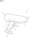
- Fig. 1 shows a schematic and simplified view of an electric, pistol-like and in particular battery-operated hand-held device 10 according to an embodiment of the invention.
- the Fig. 1 The hand-held device 10 shown has a device body 12, by means of which a workpiece can be processed in an electrically activated manner.
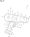
- the invention is not limited to the use of the electric, pistol-like hand-held device as a hot air gun (as with reference to Fig. 6 will be described in more detail below) but can provide a variety of uses.
- the electric, pistol-like hand-held device is a cordless screwdriver, a drill (battery-operated or corded), a hot glue gun, a milling device, a soldering device, a welding device, a stud welding device or generally a hand-held device that requires a locking mechanism or safety mechanism due to dangerous operation when machining a workpiece.
- the device body 12 is preferably provided as an elongated housing, wherein a workpiece processing area 14 can be provided on the front side or distal end of the device body 12. This can be the case in Fig. 6 In the embodiment shown, for example, an air outlet is used as a hot air blower for hot air. However, it is also conceivable that the workpiece processing area 14 is provided, for example, as a drill chuck in which a drilling tool can be accommodated.
- the elongated device body 12 extends along a longitudinal direction A.
- the hand-held device 10 further comprises a handle part 16 which is connected at an angle to the device body 12.
- the handle part 16 extends along a handle axis B such that the longitudinal direction A and the handle axis B are arranged at an angle to one another such that they are at an angle of 70° to 110°, or 80° to 100°, or in particular substantially perpendicular to one another.
- the handle part 16 is thus connected with its first, upper end 18 to a rear, lower region 20 of the device body 12.
- top and bottom refer to a position of the hand-held device 10 in which the handle part 16 is aligned with its handle axis B substantially parallel to the direction of gravity, with the device body 12 being arranged above the handle part 16.
- the longitudinal direction A of the device body 12 runs essentially perpendicular to the direction of gravity and essentially parallel to a horizontal.
- a front region of the hand-held device 10 coincides with the workpiece processing region 14 and a rear region or back region 22 of the device body 12 coincides with a region in which the handle part 16 is provided and which faces a user.
- the unlocking of the hand-held device 10 according to the invention is particularly advantageously supported by the provision of a battery module 24, which can be detachably connected to the handle part 16 at its lower second end facing away from the device body 12 and is provided for supplying the hand-held device 10 with electrical energy.
- the battery module 24 is attached or locked in place in a known manner on the underside of the pistol-shaped handle part 16 of the handle 10.
- the accumulator module 24 has electrical storage means 24a, which are preferably designed as electrical accumulators.
- a lithium-ion battery can be provided as the electrical accumulator 24a, which can be set up for an operating voltage of 18 V.
- the accumulator module 24 By providing the accumulator module 24 as a power supply, operating powers for the handheld device 10 in the range of 600 W to 1200 W can be provided.
- the handle part 16 By providing the accumulator module 24 on the underside of the handle part 16, the handle part 16 extends with its handle axis B perpendicularly, i.e. parallel to the direction of gravity, whereby the unlocking of the handset 10 according to the invention described below is enabled or at least facilitated.
- the electric, pistol-like handheld device 10 has an actuating device 26 for manual activation and/or deactivation of the handheld device 10, which can be arranged on the device body 12 or the handle part 16.
- the actuating device 26 is arranged on the handle part 16, but it is also conceivable that the actuating device 26 is provided on the device body 12.
- the hand-held device 10 has an unlocking device 28, by means of which the actuating device 26 can be manually unlocked and/or locked.
- the unlocking device 28 is arranged according to the invention on the device body 12 or the handle part 16 in such a way that unlocking occurs by supporting the handheld device 12 in stable equilibrium on one of the fingers of a user's hand (not shown) when a user grasps the handle part 16.
- the weight distribution of the handheld device 10 is therefore such that when a user grasps the handle part 16 with a user's hand, one of the fingers of the user's hand, for example the middle finger, slides upwards on the handle part 16 due to the weight of the battery module 24 and in doing so strikes the unlocking device 28, whereby unlocking of the handheld device 10 is triggered when the handheld device 10 is grasped.
- the hand-held device 10 lies balanced in a stable equilibrium with the unlocking device 28 on one of the fingers of the user's hand and is carried or supported in equilibrium by this finger, wherein the unlocking device 28 is actuated by the corresponding supporting force.
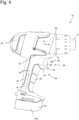
- the hand-held device 10 has a support mandrel 30 which projects forwards from a finger grip area 32 of the handle part 16, i.e. in the direction of the workpiece processing area 14 of the hand-held device 10 and has the unlocking device 28 on its underside, i.e. the side facing the accumulator module 24, wherein the unlocking takes place by supporting the support mandrel 30 on one of the fingers of the user's hand.
- the support pin 30 can be concave on its underside to at least partially enclose the unlocking Fingers against the direction of gravity.
- the finger grip area 32 of the handle part 16 is an area in which the fingers of a user's hand come to rest when using the handset 10. This finger grip area 32 is located on the opposite side of a palm grip area 34 of the handle part 16. As further shown in Fig. 4 As can be seen, the crescent-shaped support pin 30 prevents the hand-held device 10 from slipping off the unlocking finger, on which the handle 10 rests in a stable equilibrium when grasped. Furthermore, the support pin 30 can be provided on the handle part 16 in such a way that the actuating device 26, in particular a push button switch, is arranged between the device body 12 and the support pin 30. This ensures that unintentional actuation is not made more difficult or prevented by the index finger of a user, even when unlocking.
- unlocking device should be understood in general to mean that a locking of the actuating device 26 is removed by any kind of actuation of the unlocking device 28.
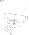
- This unlocking of the actuating device 26 can, for example, be carried out electrically by providing pushbutton switches for the actuating device 26 and the unlocking device 28 (as in Fig. 1 shown), electronically by providing touch sensors (such as in Fig. 2 shown) or mechanically by providing a release mechanism (as for example in Fig. 3 and Fig. 5 shown).
- the unlocking device 28 can thus also be referred to as an unlocking unit, switch-on locking unit, or simply as a locking unit.
- the actuating device 26 comprises an electrical actuating pushbutton switch 36, which is actuated by an activation force against a restoring force transverse to the handle axis B of the handle part 16 by one of the fingers of the user's hand.
- the actuating device 26 is advantageously provided on the handle part 16 or the device body 12 in such a way that the actuation takes place by means of an index finger of the user's hand.
- the electrical actuation switch 36 is more precisely in Fig. 5 shown.
- the actuating pushbutton switch 36 has a button element 38 which is connected to an actuating switching part 42 via a piston element 40 and is guided linearly between an off position and an on position by the piston element 40.
- the piston element 40 is guided into the switching part 42 and triggers a electrical switching process or, depending on a gradual depression depth, a potentiometer process.
- the piston element 40 is moved into an off position against the direction of the button press, for example by a return spring, and is held in this position.
- the unlocking device 28 comprises an electrical unlocking pushbutton switch 44, which is actuated by a supporting force against gravity along the handle axis B of the handle part 16 by one of the fingers of the user's hand.
- the unlocking device 28 is particularly advantageously provided on the handle part 16 or the device body 12 in such a way that the unlocking takes place by means of a middle finger of the user's hand.
- the electrical release button 44 can be designed in a similar way to the electrical actuation button 36.
- the actuating device 26 is unlocked or released, for example, by a series connection of the actuating pushbutton switch 36 and the unlocking pushbutton switch 44, wherein the unlocking pushbutton switch is held in a "normally off” or normally open contact position by a return spring and, when actuated, closes the circuit for operating the handset 10 while the actuating pushbutton switch 36 is simultaneously held down.
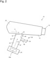
- Fig. 2 shows a further embodiment of a hand-held device 10 according to the invention.
- the actuating device 26 comprises an actuating touch sensor 46, which is actuated by touching the actuating touch sensor 46 in a direction transverse to the handle axis B of the handle part 16 by one of the fingers of the user's hand.
- the hand-held device 10 can also be made of Fig. 2 for the actuating device 26 an actuating push button switch 36, as in Fig. 1 and Fig. 5 shown, will be used.
- the unlocking device 28 comprises an unlocking touch sensor 48, which is actuated by touching the unlocking touch sensor 48 in a direction along the handle axis B of the handle part 16 by one of the fingers of the user's hand.
- the unlocking or unlocking of the actuating device 26 by The unlocking touch sensor 48 can be activated electronically, with an electronic control unit (not shown) capacitively detecting a touch of the unlocking touch sensor 48, for example, and, in the event of a touch event, releasing or closing an electrical circuit which is connected in series with the actuating device 28 for the electrical operation of the handset 10.
- the unlocking device 28 comprises a mechanical unlocking mechanism 50, which mechanically unlocks or releases the actuating device 26 by means of a supporting force against gravity along the handle axis B of the handle part 16 by one of the fingers of the user's hand.
- the mechanical unlocking mechanism 50 can block or lock an actuating pushbutton switch 36 in its actuating direction in different ways.
- the mechanical unlocking mechanism 50 can have a button area 52, which comes into contact with the unlocking finger, and a locking element 54, which releasably makes it difficult or impossible to move the actuating pushbutton switch by means of a frictional or positive locking, or at least blocks it in the actuating direction, so that actuation of the handset 10 is prevented or at least made more difficult.
- FIG. 5 A particularly advantageous embodiment of the mechanical unlocking mechanism 50 is shown in Fig. 5 shown.
- the mechanical unlocking mechanism 50 has an unlocking rocker 56, which is held in a locking position by a return spring 60 connected to its first end 58, wherein the second end 62 of the unlocking rocker 58 enables an actuation of the actuating device 26, in which Fig. 5 shown embodiment of the actuating pushbutton switch 36 is blocked.
- the return spring 60 is designed as a compression spring which engages in a receiving projection 58a of the first end 58 of the release rocker 58 and is supported by a base area of a spring bearing 64 in the handle part 16.
- the pivot bearing 66 of the release rocker 58 is also firmly connected to the handle part 16 so that the release rocker 58 can pivot from a locking position into an unlocking position against the spring force of the return spring 60.
- the second end 62 of the release rocker 58 is U-shaped, whereby during unlocking a rear edge area of the button part 38 of the actuating device 26 is centered in the U-shaped end 62.
- the release rocker 58 is guided, and when locked, the rear edge region of the button part 38, which is designed as an injection-molded hollow part, hits an edge region or the locking element 54 of the U-shaped end 62 of the release rocker 58.
- the U-shaped end 62 of the release rocker 58 is designed such that the button region 52 of the mechanical release mechanism 50 is provided on one leg of the U-shaped end 62 and the locking element 54 of the mechanical release mechanism 50 is provided on the other leg of the U-shaped end 62.
- the locking element 54 is also pivoted upwards, whereby the button element 38 of the actuating pushbutton switch, which is designed as a hollow part, is no longer blocked by the locking element 54 and can move freely in the actuating direction in the central region of the U-shaped end 62.
- both the actuating device 26 and the unlocking device 28 are completely symmetrical or mirror-symmetrical with respect to the plane spanned by the handle axis B and the longitudinal direction A.
- the unlocking device 28 and the actuating device 26 are provided so symmetrically or mirror-symmetrically on the handle part 16 or the device body 12 that unlocking or actuation can be carried out in the same way using a right or left user hand.
- the hand-held device 10 according to the invention can be used and unlocked in the same way by left-handed or right-handed people, and there is no disadvantage if a user changes hands.
- a mechanical lock for the on/off switch is provided.
- the mechanical blocking prevents the on/off switch from being accidentally activated and thus the device from starting.
- the lock engages behind the housing of the on/off switch when it is not activated. If it is activated, the path is cleared and the on/off switch can be pressed. When the on/off switch is pressed, the safety lock no longer needs to be pressed; it is instead held in this position.
- the position of the safety lock is selected so that the natural hand position on the handle already activates the safety lock, but accidental activation is made unlikely. This enables intuitive operation.
- a reliable mechanical blockage of the on/off switch is provided by the release mechanism. 50, as in Fig. 5 shown. This also ensures smooth movement of the unlocking mechanism.
- the unlocking mechanism 50 has few mechanical parts and is easy to assemble. The simple assembly and the few, essentially two mechanical parts reduce assembly and production costs, while the utility value of the handset 10 is increased.
- FIG. 6 A design of the hand-held device 10 as a hot air gun is shown.
- the Fig. 6 The hand-held device 10 shown has an elongated device body 12 with a hot air blower 68, on which an air outlet for heated air is provided as the workpiece processing area 14.
- This heated air is generated by a heating device 70, through which air is sucked in through an air inlet (not shown) by means of a blower device 72 and can exit from the air outlet 14 heated to an operating temperature of up to approximately 700 °C.
- the operating temperature is between 300 °C and 500 °C.
- the blower device 72 has an electric motor 74 and at least one fan wheel 76 that can be driven by the electric motor 74.
- the electric motor 74 of the blower device 72 is designed as a brush motor.
- the control unit 78 is electrically connected to the blower device 72 and the heating device 70.
- the heating device 70 is designed to generate a constant heating output in the range between 300 W and 1,200 W, preferably in the range between 400 W and 600 W or between 800 W and 1,000 W, in particular in the range between 500 W and 600 W or 900 W and 1,000 W.
- the further operation of the hand-held device 10 designed as a hot air blower corresponds to that already described with reference to the Figures 1 to 5 described features, whereby different actuation and release mechanisms, as described above, can be freely combined with each other.
- the Fig. 2 The embodiment shown is not limited to the fact that a touch sensor must be provided for both actuation and unlocking.
Landscapes
- Engineering & Computer Science (AREA)
- Mechanical Engineering (AREA)
- General Engineering & Computer Science (AREA)
- Physics & Mathematics (AREA)
- Thermal Sciences (AREA)
- Chemical & Material Sciences (AREA)
- Combustion & Propulsion (AREA)
- Portable Nailing Machines And Staplers (AREA)
Claims (14)
- Appareil à main électrique de type pistolet (10) comprenant- un corps d'appareil (12) pour l'usinage activé électriquement d'une pièce à usiner,- une partie de préhension (16) reliée de manière angulaire au corps de l'appareil (12),- un dispositif d'actionnement (26) pour l'activation et/ou la désactivation manuelle de l'appareil à main (10), qui est disposé sur le corps d'appareil (12) ou sur la partie de préhension (16), et- un dispositif de déverrouillage (28) pour le déverrouillage manuel et/ou le verrouillage du dispositif d'actionnement (26), caractérisé par- un mandrin d'appui (30) qui fait saillie vers l'avant à partir d'une zone de préhension des doigts (32) de la partie de préhension (16) et qui présente le dispositif de déverrouillage (28) sur sa face inférieure, le déverrouillage étant effectué par un appui du mandrin d'appui (30) sur l'un des doigts de la main de l'utilisateur.
- Appareil à main (10) selon la revendication 1, dans lequel le mandrin d'appui (30) est concave sur sa face inférieure pour recevoir le doigt de déverrouillage en l'entourant au moins partiellement dans le sens opposé à la direction de la gravité.
- Appareil à main (10) selon l'une quelconque des revendications précédentes, dans lequel le dispositif d'actionnement (26) comprend un bouton-poussoir d'actionnement électrique (36) actionné par une force d'activation s'opposant à une force de rappel transversale à l'axe de préhension (B) de la partie de préhension (16) par l'un des doigts de la main de l'utilisateur.
- Appareil à main (10) selon l'une quelconque des revendications précédentes, dans lequel le dispositif de déverrouillage (28) comprend un bouton-poussoir de déverrouillage électrique (44) actionné par une force d'appui s'opposant à la gravité le long de l'axe de préhension (B) de la partie de préhension (16) par l'un des doigts de la main de l'utilisateur.
- Appareil à main (10) selon l'une quelconque des revendications 1 ou 2, dans lequel le dispositif d'actionnement (26) comprend un capteur tactile d'actionnement (46) actionné en touchant le capteur tactile d'actionnement (46) dans une direction transversale à l'axe de préhension (B) de la partie de préhension (16) au moyen de l'un des doigts de la main de l'utilisateur.
- Appareil à main (10) selon l'une des revendications 1 ou 2, dans lequel le dispositif de déverrouillage (28) comprend un capteur tactile de déverrouillage (48) actionné en touchant le capteur tactile de déverrouillage (48) dans une direction le long de l'axe de préhension (B) de la partie de préhension (16) au moyen de l'un des doigts de la main de l'utilisateur.
- Appareil à main (10) selon l'une des revendications 1 à 3, dans lequel le dispositif de déverrouillage (28) comprend un mécanisme de déverrouillage mécanique (50) qui déverrouille mécaniquement le dispositif d'actionnement par une force d'appui contre la gravité le long de l'axe de préhension (B) de la partie de préhension (16) au moyen de l'un des doigts de la main de l'utilisateur.
- Appareil à main (10) selon la revendication 7, dans lequel le mécanisme de déverrouillage (50) mécanique comporte une bascule de déverrouillage (56) maintenue dans une position de verrouillage par un ressort de rappel (60) relié à sa première extrémité (58), la deuxième extrémité (62) de la bascule de déverrouillage (58) bloquant un actionnement du dispositif d'actionnement (26).
- Appareil à main (10) selon la revendication 8, dans lequel la deuxième extrémité (62) de la bascule de déverrouillage (56) est réalisée en forme de U et dans lequel, lors d'un déverrouillage, une partie de touche (38) du dispositif d'actionnement (26) est guidée au centre dans l'extrémité en forme de U (62) de la bascule de déverrouillage (56) et, lors d'un verrouillage, la partie de touche (38) vient buter contre un élément de blocage (54) sur l'extrémité en forme de U (62) de la bascule de déverrouillage (56).
- Appareil à main (10) selon l'une quelconque des revendications précédentes, dans lequel le dispositif d'actionnement (26) est prévu sur la partie de préhension (16) ou sur le corps de l'appareil (12) de manière à ce que l'actionnement se fasse au moyen d'un index de la main de l'utilisateur.
- Appareil à main (10) selon l'une quelconque des revendications précédentes, dans lequel le dispositif de déverrouillage (28) est prévu sur la partie de préhension (16) ou sur le corps de l'appareil (12) de manière à ce que le déverrouillage se fasse au moyen d'un majeur de la main de l'utilisateur.
- Appareil à main (10) selon l'une quelconque des revendications précédentes, dans lequel le dispositif de déverrouillage (28) et le dispositif d'actionnement (26) sont prévus symétriquement sur la partie de préhension (16) ou sur le corps de l'appareil (12) de telle sorte qu'un déverrouillage et un actionnement peuvent être réalisés de la même manière au moyen d'une main droite ou d'une main gauche de l'utilisateur.
- Appareil à main (10) selon l'une quelconque des revendications précédentes, dans lequel la partie de préhension (16) peut être reliée en énergie électrique de manière amovible, à son extrémité inférieure opposée au corps de l'appareil (12), à un module d'accumulateur électrique (24) pour l'alimentation de l'appareil à main (10).
- Appareil à main (10) selon l'une quelconque des revendications précédentes, dans lequel le corps de l'appareil (12) comporte une soufflerie d'air chaud (68).
Applications Claiming Priority (2)
| Application Number | Priority Date | Filing Date | Title |
|---|---|---|---|
| DE102019126493.6A DE102019126493A1 (de) | 2019-10-01 | 2019-10-01 | Elektrisches, pistolenartiges Handgerät |
| PCT/EP2020/067535 WO2021063553A1 (fr) | 2019-10-01 | 2020-06-23 | Appareil à main électrique de type pistolet |
Publications (2)
| Publication Number | Publication Date |
|---|---|
| EP4013571A1 EP4013571A1 (fr) | 2022-06-22 |
| EP4013571B1 true EP4013571B1 (fr) | 2024-10-16 |
Family
ID=71138758
Family Applications (1)
| Application Number | Title | Priority Date | Filing Date |
|---|---|---|---|
| EP20734530.7A Active EP4013571B1 (fr) | 2019-10-01 | 2020-06-23 | Appareil à main électrique de type pistolet |
Country Status (5)
| Country | Link |
|---|---|
| US (1) | US12358117B2 (fr) |
| EP (1) | EP4013571B1 (fr) |
| CN (1) | CN114072584B (fr) |
| DE (1) | DE102019126493A1 (fr) |
| WO (1) | WO2021063553A1 (fr) |
Families Citing this family (5)
| Publication number | Priority date | Publication date | Assignee | Title |
|---|---|---|---|---|
| EP3770448A1 (fr) * | 2019-07-23 | 2021-01-27 | Lercher GmbH | Système de liaison pour la liaison mécanique de deux matériaux |
| DE102024102484A1 (de) | 2024-01-29 | 2025-07-31 | Leister Technologies Ag | Heißlufthandgerät und Verfahren zum Betrieb eines Heißlufthandgeräts |
| EP4624103A1 (fr) * | 2024-03-28 | 2025-10-01 | Hilti Aktiengesellschaft | Machine-outil portative |
| EP4624102A1 (fr) * | 2024-03-28 | 2025-10-01 | Hilti Aktiengesellschaft | Outil électrique portatif |
| EP4686531A1 (fr) * | 2024-07-29 | 2026-02-04 | Nanjing Chervon Industry Co., Ltd. | Outil électrique |
Citations (1)
| Publication number | Priority date | Publication date | Assignee | Title |
|---|---|---|---|---|
| US20130205538A1 (en) * | 2012-02-10 | 2013-08-15 | Dyson Technology Limited | Vacuum cleaner |
Family Cites Families (27)
| Publication number | Priority date | Publication date | Assignee | Title |
|---|---|---|---|---|
| US3781579A (en) * | 1973-01-03 | 1973-12-25 | Black & Decker Mfg Co | Protected lock means for electrically-operated,hand-manipulated tools |
| US4296290A (en) * | 1980-01-16 | 1981-10-20 | The Singer Company | Safety lock-on motor control |
| EP0048124A3 (fr) * | 1980-09-12 | 1982-12-08 | Skil Nederland B.V. | Dispositif de commutateur de contrôle de vitesse |
| DE8714271U1 (de) * | 1987-10-27 | 1987-12-17 | Kopperschmidt-Mueller Gmbh & Co Kg, 4800 Bielefeld | Spritz- oder Sprühpistole |
| US5195164A (en) * | 1990-05-17 | 1993-03-16 | Lambert William S | Electric heater/blowers with selectively-locked output variable heat and blower controls |
| AUPS001902A0 (en) * | 2002-01-18 | 2002-02-07 | Ramsay, George Stephen | Improvement to power tools and trigger handles therefore |
| DE10336874A1 (de) * | 2003-08-11 | 2005-03-10 | Hilti Ag | Griffanordnung |
| US7434715B2 (en) * | 2003-09-29 | 2008-10-14 | Ethicon Endo-Surgery, Inc. | Surgical stapling instrument having multistroke firing with opening lockout |
| US6812425B1 (en) * | 2003-11-24 | 2004-11-02 | Defond Components Limited | Locking trigger switch mechanism |
| US6989503B2 (en) * | 2004-03-22 | 2006-01-24 | Defond Components Limited | Power tool trigger assembly |
| EP1640118B1 (fr) * | 2004-09-22 | 2007-11-14 | BLACK & DECKER INC. | Bouton poussoir blocable pour marteau perforateur |
| JP2008080421A (ja) * | 2006-09-26 | 2008-04-10 | Matsushita Electric Works Ltd | 手持ち工具 |
| DE102006060880A1 (de) * | 2006-12-22 | 2008-06-26 | Metabowerke Gmbh | Elektrohandwerkzeuggerät |
| AT10398U1 (de) * | 2007-12-21 | 2009-02-15 | Caracal Internat L L C | Waffe, insbesondere handfeuerwaffe |
| JP5185741B2 (ja) * | 2008-09-02 | 2013-04-17 | 株式会社マキタ | 作業工具 |
| DE102010053086A1 (de) * | 2010-12-01 | 2012-06-06 | Andreas Stihl Ag & Co. Kg | Handgeführtes Arbeitsgerät |
| DE102013213806A1 (de) * | 2012-11-15 | 2014-05-15 | Robert Bosch Gmbh | Werkzeugvorsatz für eine Handwerkzeugmaschine |
| DE102012223931A1 (de) * | 2012-12-20 | 2014-06-26 | Robert Bosch Gmbh | Werkzeugmaschine mit einer Schaltereinrichtung |
| CN203712650U (zh) * | 2013-03-12 | 2014-07-16 | 英格索尔-兰德公司 | 手持式电动工具 |
| EP2884515A1 (fr) * | 2013-12-16 | 2015-06-17 | HILTI Aktiengesellschaft | Commutateur d'appareil pour outils électriques avec blocage du commutateur |
| WO2016196891A1 (fr) * | 2015-06-05 | 2016-12-08 | Ingersoll-Rand Company | Interfaces utilisateur de machine-outil électrique |
| DE102016012204A1 (de) * | 2015-10-23 | 2017-04-27 | Bruno Gruber | Schrauber, mit einer elektrischen Schaltanordnung |
| DE102015225723A1 (de) * | 2015-12-17 | 2017-06-22 | Robert Bosch Gmbh | Handwerkzeugmaschinenvorrichtung |
| DE102015226801A1 (de) * | 2015-12-29 | 2017-06-29 | Robert Bosch Gmbh | Elektrohandwerkzeug, Elektrohandwerkzeugsystem und Verfahren zum Betreiben |
| EP3346126B1 (fr) * | 2017-01-04 | 2022-11-30 | Techtronic Cordless GP | Gonfleur |
| US10126080B2 (en) * | 2017-03-09 | 2018-11-13 | Roy Martin | Biometric firearms safety system |
| DE102022211593A1 (de) * | 2022-11-02 | 2024-05-02 | Robert Bosch Gesellschaft mit beschränkter Haftung | Verfahren zur Anzeige einer Zielerreichung einer Handwerkzeugmaschine |
-
2019
- 2019-10-01 DE DE102019126493.6A patent/DE102019126493A1/de active Pending
-
2020
- 2020-06-23 CN CN202080046648.6A patent/CN114072584B/zh active Active
- 2020-06-23 EP EP20734530.7A patent/EP4013571B1/fr active Active
- 2020-06-23 WO PCT/EP2020/067535 patent/WO2021063553A1/fr not_active Ceased
- 2020-06-23 US US17/423,458 patent/US12358117B2/en active Active
Patent Citations (1)
| Publication number | Priority date | Publication date | Assignee | Title |
|---|---|---|---|---|
| US20130205538A1 (en) * | 2012-02-10 | 2013-08-15 | Dyson Technology Limited | Vacuum cleaner |
Also Published As
| Publication number | Publication date |
|---|---|
| CN114072584B (zh) | 2024-07-26 |
| US12358117B2 (en) | 2025-07-15 |
| EP4013571A1 (fr) | 2022-06-22 |
| DE102019126493A1 (de) | 2021-04-01 |
| WO2021063553A1 (fr) | 2021-04-08 |
| US20220118597A1 (en) | 2022-04-21 |
| CN114072584A (zh) | 2022-02-18 |
Similar Documents
| Publication | Publication Date | Title |
|---|---|---|
| EP4013571B1 (fr) | Appareil à main électrique de type pistolet | |
| DE102006048315A1 (de) | Handwerkzeugmaschine, insbesondere elektrische Schere | |
| DE102014201920A1 (de) | Handwerkzeugmaschinenbetätigungselement für eine Stichsäge, sowie Stichsäge | |
| DE102014214982A1 (de) | Elektrowerkzeugmaschine | |
| DE10353302A1 (de) | Elektrowerkzeug und Verfahren zur Steuerung eines Elektrowerkzeugs | |
| EP3389950B1 (fr) | Dispositif pour machine-outil portative | |
| EP2910339B1 (fr) | Poignée pour un appareil de travail doté d'un moteur d'entraînement | |
| DE102013212573B4 (de) | Handwerkzeugmaschinenschaltvorrichtung | |
| EP2346654B1 (fr) | Outil électrique, en particulier scie | |
| DE102019213720A1 (de) | Handwerkzeugmaschine und Verfahren zum Betreiben der Handwerkzeugmaschine | |
| DE102019213742A1 (de) | Handwerkzeugmaschine | |
| EP1789235A1 (fr) | Outil electrique a double interrupteur | |
| DE112017006690T5 (de) | Elektrischer Schraubendreher | |
| EP2465615B1 (fr) | Dispositif d'application de colle | |
| EP2140466B1 (fr) | Prise électrique | |
| EP1059025A2 (fr) | Outil de jardin motorisé, notamment taille-haie | |
| DE102022209164A1 (de) | Absaugvorrichtung zu einer lösbaren Verbindung mit einer Handwerkzeugmaschine | |
| DE102006018006B4 (de) | Akkupack und Elektrogerät | |
| EP4264145A1 (fr) | Ventilateur à air chaud | |
| DE19903787A1 (de) | Handgehaltenes Elektrowerkzeug | |
| WO2025162881A1 (fr) | Appareil à main à air chaud et procédé pour faire fonctionner un appareil à main à air chaud | |
| DE102012212058A1 (de) | Schnellspannvorrichtung | |
| DE102006060880A1 (de) | Elektrohandwerkzeuggerät | |
| DE102017100089B4 (de) | Auslösevorrichtung | |
| DE10148513B4 (de) | Vorrichtung zur Steuerung eines elektrischen Gerätes |
Legal Events
| Date | Code | Title | Description |
|---|---|---|---|
| STAA | Information on the status of an ep patent application or granted ep patent |
Free format text: STATUS: UNKNOWN |
|
| STAA | Information on the status of an ep patent application or granted ep patent |
Free format text: STATUS: THE INTERNATIONAL PUBLICATION HAS BEEN MADE |
|
| PUAI | Public reference made under article 153(3) epc to a published international application that has entered the european phase |
Free format text: ORIGINAL CODE: 0009012 |
|
| STAA | Information on the status of an ep patent application or granted ep patent |
Free format text: STATUS: REQUEST FOR EXAMINATION WAS MADE |
|
| 17P | Request for examination filed |
Effective date: 20210609 |
|
| AK | Designated contracting states |
Kind code of ref document: A1 Designated state(s): AL AT BE BG CH CY CZ DE DK EE ES FI FR GB GR HR HU IE IS IT LI LT LU LV MC MK MT NL NO PL PT RO RS SE SI SK SM TR |
|
| DAV | Request for validation of the european patent (deleted) | ||
| DAX | Request for extension of the european patent (deleted) | ||
| P01 | Opt-out of the competence of the unified patent court (upc) registered |
Effective date: 20230512 |
|
| GRAP | Despatch of communication of intention to grant a patent |
Free format text: ORIGINAL CODE: EPIDOSNIGR1 |
|
| STAA | Information on the status of an ep patent application or granted ep patent |
Free format text: STATUS: GRANT OF PATENT IS INTENDED |
|
| INTG | Intention to grant announced |
Effective date: 20240515 |
|
| GRAS | Grant fee paid |
Free format text: ORIGINAL CODE: EPIDOSNIGR3 |
|
| GRAA | (expected) grant |
Free format text: ORIGINAL CODE: 0009210 |
|
| STAA | Information on the status of an ep patent application or granted ep patent |
Free format text: STATUS: THE PATENT HAS BEEN GRANTED |
|
| AK | Designated contracting states |
Kind code of ref document: B1 Designated state(s): AL AT BE BG CH CY CZ DE DK EE ES FI FR GB GR HR HU IE IS IT LI LT LU LV MC MK MT NL NO PL PT RO RS SE SI SK SM TR |
|
| REG | Reference to a national code |
Ref country code: GB Ref legal event code: FG4D Free format text: NOT ENGLISH |
|
| REG | Reference to a national code |
Ref country code: CH Ref legal event code: EP Ref country code: DE Ref legal event code: R096 Ref document number: 502020009510 Country of ref document: DE |
|
| REG | Reference to a national code |
Ref country code: IE Ref legal event code: FG4D Free format text: LANGUAGE OF EP DOCUMENT: GERMAN |
|
| REG | Reference to a national code |
Ref country code: LT Ref legal event code: MG9D |
|
| REG | Reference to a national code |
Ref country code: NL Ref legal event code: MP Effective date: 20241016 |
|
| PG25 | Lapsed in a contracting state [announced via postgrant information from national office to epo] |
Ref country code: NL Free format text: LAPSE BECAUSE OF FAILURE TO SUBMIT A TRANSLATION OF THE DESCRIPTION OR TO PAY THE FEE WITHIN THE PRESCRIBED TIME-LIMIT Effective date: 20241016 |
|
| PG25 | Lapsed in a contracting state [announced via postgrant information from national office to epo] |
Ref country code: NL Free format text: LAPSE BECAUSE OF FAILURE TO SUBMIT A TRANSLATION OF THE DESCRIPTION OR TO PAY THE FEE WITHIN THE PRESCRIBED TIME-LIMIT Effective date: 20241016 |
|
| PG25 | Lapsed in a contracting state [announced via postgrant information from national office to epo] |
Ref country code: IS Free format text: LAPSE BECAUSE OF FAILURE TO SUBMIT A TRANSLATION OF THE DESCRIPTION OR TO PAY THE FEE WITHIN THE PRESCRIBED TIME-LIMIT Effective date: 20250216 Ref country code: HR Free format text: LAPSE BECAUSE OF FAILURE TO SUBMIT A TRANSLATION OF THE DESCRIPTION OR TO PAY THE FEE WITHIN THE PRESCRIBED TIME-LIMIT Effective date: 20241016 Ref country code: PT Free format text: LAPSE BECAUSE OF FAILURE TO SUBMIT A TRANSLATION OF THE DESCRIPTION OR TO PAY THE FEE WITHIN THE PRESCRIBED TIME-LIMIT Effective date: 20250217 |
|
| PG25 | Lapsed in a contracting state [announced via postgrant information from national office to epo] |
Ref country code: FI Free format text: LAPSE BECAUSE OF FAILURE TO SUBMIT A TRANSLATION OF THE DESCRIPTION OR TO PAY THE FEE WITHIN THE PRESCRIBED TIME-LIMIT Effective date: 20241016 |
|
| PG25 | Lapsed in a contracting state [announced via postgrant information from national office to epo] |
Ref country code: BG Free format text: LAPSE BECAUSE OF FAILURE TO SUBMIT A TRANSLATION OF THE DESCRIPTION OR TO PAY THE FEE WITHIN THE PRESCRIBED TIME-LIMIT Effective date: 20241016 |
|
| PG25 | Lapsed in a contracting state [announced via postgrant information from national office to epo] |
Ref country code: ES Free format text: LAPSE BECAUSE OF FAILURE TO SUBMIT A TRANSLATION OF THE DESCRIPTION OR TO PAY THE FEE WITHIN THE PRESCRIBED TIME-LIMIT Effective date: 20241016 |
|
| PG25 | Lapsed in a contracting state [announced via postgrant information from national office to epo] |
Ref country code: NO Free format text: LAPSE BECAUSE OF FAILURE TO SUBMIT A TRANSLATION OF THE DESCRIPTION OR TO PAY THE FEE WITHIN THE PRESCRIBED TIME-LIMIT Effective date: 20250116 |
|
| PG25 | Lapsed in a contracting state [announced via postgrant information from national office to epo] |
Ref country code: GR Free format text: LAPSE BECAUSE OF FAILURE TO SUBMIT A TRANSLATION OF THE DESCRIPTION OR TO PAY THE FEE WITHIN THE PRESCRIBED TIME-LIMIT Effective date: 20250117 Ref country code: LV Free format text: LAPSE BECAUSE OF FAILURE TO SUBMIT A TRANSLATION OF THE DESCRIPTION OR TO PAY THE FEE WITHIN THE PRESCRIBED TIME-LIMIT Effective date: 20241016 |
|
| PG25 | Lapsed in a contracting state [announced via postgrant information from national office to epo] |
Ref country code: PL Free format text: LAPSE BECAUSE OF FAILURE TO SUBMIT A TRANSLATION OF THE DESCRIPTION OR TO PAY THE FEE WITHIN THE PRESCRIBED TIME-LIMIT Effective date: 20241016 |
|
| PG25 | Lapsed in a contracting state [announced via postgrant information from national office to epo] |
Ref country code: RS Free format text: LAPSE BECAUSE OF FAILURE TO SUBMIT A TRANSLATION OF THE DESCRIPTION OR TO PAY THE FEE WITHIN THE PRESCRIBED TIME-LIMIT Effective date: 20250116 |
|
| PG25 | Lapsed in a contracting state [announced via postgrant information from national office to epo] |
Ref country code: SM Free format text: LAPSE BECAUSE OF FAILURE TO SUBMIT A TRANSLATION OF THE DESCRIPTION OR TO PAY THE FEE WITHIN THE PRESCRIBED TIME-LIMIT Effective date: 20241016 |
|
| PGFP | Annual fee paid to national office [announced via postgrant information from national office to epo] |
Ref country code: DE Payment date: 20250605 Year of fee payment: 6 |
|
| PG25 | Lapsed in a contracting state [announced via postgrant information from national office to epo] |
Ref country code: DK Free format text: LAPSE BECAUSE OF FAILURE TO SUBMIT A TRANSLATION OF THE DESCRIPTION OR TO PAY THE FEE WITHIN THE PRESCRIBED TIME-LIMIT Effective date: 20241016 |
|
| PGFP | Annual fee paid to national office [announced via postgrant information from national office to epo] |
Ref country code: GB Payment date: 20250627 Year of fee payment: 6 |
|
| REG | Reference to a national code |
Ref country code: DE Ref legal event code: R097 Ref document number: 502020009510 Country of ref document: DE |
|
| PG25 | Lapsed in a contracting state [announced via postgrant information from national office to epo] |
Ref country code: EE Free format text: LAPSE BECAUSE OF FAILURE TO SUBMIT A TRANSLATION OF THE DESCRIPTION OR TO PAY THE FEE WITHIN THE PRESCRIBED TIME-LIMIT Effective date: 20241016 |
|
| PG25 | Lapsed in a contracting state [announced via postgrant information from national office to epo] |
Ref country code: RO Free format text: LAPSE BECAUSE OF FAILURE TO SUBMIT A TRANSLATION OF THE DESCRIPTION OR TO PAY THE FEE WITHIN THE PRESCRIBED TIME-LIMIT Effective date: 20241016 |
|
| PG25 | Lapsed in a contracting state [announced via postgrant information from national office to epo] |
Ref country code: SK Free format text: LAPSE BECAUSE OF FAILURE TO SUBMIT A TRANSLATION OF THE DESCRIPTION OR TO PAY THE FEE WITHIN THE PRESCRIBED TIME-LIMIT Effective date: 20241016 |
|
| PG25 | Lapsed in a contracting state [announced via postgrant information from national office to epo] |
Ref country code: CZ Free format text: LAPSE BECAUSE OF FAILURE TO SUBMIT A TRANSLATION OF THE DESCRIPTION OR TO PAY THE FEE WITHIN THE PRESCRIBED TIME-LIMIT Effective date: 20241016 |
|
| PG25 | Lapsed in a contracting state [announced via postgrant information from national office to epo] |
Ref country code: IT Free format text: LAPSE BECAUSE OF FAILURE TO SUBMIT A TRANSLATION OF THE DESCRIPTION OR TO PAY THE FEE WITHIN THE PRESCRIBED TIME-LIMIT Effective date: 20241016 |
|
| REG | Reference to a national code |
Ref country code: DE Ref legal event code: R081 Ref document number: 502020009510 Country of ref document: DE Owner name: STEINEL TOOLS GMBH, DE Free format text: FORMER OWNER: STEINEL GMBH, 33442 HERZEBROCK-CLARHOLZ, DE |
|
| PLBE | No opposition filed within time limit |
Free format text: ORIGINAL CODE: 0009261 |
|
| STAA | Information on the status of an ep patent application or granted ep patent |
Free format text: STATUS: NO OPPOSITION FILED WITHIN TIME LIMIT |
|
| PG25 | Lapsed in a contracting state [announced via postgrant information from national office to epo] |
Ref country code: SE Free format text: LAPSE BECAUSE OF FAILURE TO SUBMIT A TRANSLATION OF THE DESCRIPTION OR TO PAY THE FEE WITHIN THE PRESCRIBED TIME-LIMIT Effective date: 20241016 |
|
| 26N | No opposition filed |
Effective date: 20250717 |
|
| REG | Reference to a national code |
Ref country code: GB Ref legal event code: 732E Free format text: REGISTERED BETWEEN 20251211 AND 20251217 |
|
| REG | Reference to a national code |
Ref country code: CH Ref legal event code: H13 Free format text: ST27 STATUS EVENT CODE: U-0-0-H10-H13 (AS PROVIDED BY THE NATIONAL OFFICE) Effective date: 20260127 |
|
| PG25 | Lapsed in a contracting state [announced via postgrant information from national office to epo] |
Ref country code: MC Free format text: LAPSE BECAUSE OF FAILURE TO SUBMIT A TRANSLATION OF THE DESCRIPTION OR TO PAY THE FEE WITHIN THE PRESCRIBED TIME-LIMIT Effective date: 20241016 |
|
| PG25 | Lapsed in a contracting state [announced via postgrant information from national office to epo] |
Ref country code: LU Free format text: LAPSE BECAUSE OF NON-PAYMENT OF DUE FEES Effective date: 20250623 |
|
| REG | Reference to a national code |
Ref country code: BE Ref legal event code: MM Effective date: 20250630 |
|
| PG25 | Lapsed in a contracting state [announced via postgrant information from national office to epo] |
Ref country code: IE Free format text: LAPSE BECAUSE OF NON-PAYMENT OF DUE FEES Effective date: 20250623 |
|
| PG25 | Lapsed in a contracting state [announced via postgrant information from national office to epo] |
Ref country code: BE Free format text: LAPSE BECAUSE OF NON-PAYMENT OF DUE FEES Effective date: 20250630 |
|
| PG25 | Lapsed in a contracting state [announced via postgrant information from national office to epo] |
Ref country code: FR Free format text: LAPSE BECAUSE OF NON-PAYMENT OF DUE FEES Effective date: 20250630 |