EP4014096B1 - Queue blocks für flexible automatisierungstechnik - Google Patents
Queue blocks für flexible automatisierungstechnik Download PDFInfo
- Publication number
- EP4014096B1 EP4014096B1 EP19780103.8A EP19780103A EP4014096B1 EP 4014096 B1 EP4014096 B1 EP 4014096B1 EP 19780103 A EP19780103 A EP 19780103A EP 4014096 B1 EP4014096 B1 EP 4014096B1
- Authority
- EP
- European Patent Office
- Prior art keywords
- programmable logic
- data
- logic controller
- block
- queue
- Prior art date
- Legal status (The legal status is an assumption and is not a legal conclusion. Google has not performed a legal analysis and makes no representation as to the accuracy of the status listed.)
- Active
Links
Images


Classifications
-
- G—PHYSICS
- G05—CONTROLLING; REGULATING
- G05B—CONTROL OR REGULATING SYSTEMS IN GENERAL; FUNCTIONAL ELEMENTS OF SUCH SYSTEMS; MONITORING OR TESTING ARRANGEMENTS FOR SUCH SYSTEMS OR ELEMENTS
- G05B19/00—Program-control systems
- G05B19/02—Program-control systems electric
- G05B19/04—Program control other than numerical control, i.e. in sequence controllers or logic controllers
- G05B19/05—Programmable logic controllers, e.g. simulating logic interconnections of signals according to ladder diagrams or function charts
- G05B19/052—Linking several PLC's
-
- G—PHYSICS
- G05—CONTROLLING; REGULATING
- G05B—CONTROL OR REGULATING SYSTEMS IN GENERAL; FUNCTIONAL ELEMENTS OF SUCH SYSTEMS; MONITORING OR TESTING ARRANGEMENTS FOR SUCH SYSTEMS OR ELEMENTS
- G05B19/00—Program-control systems
- G05B19/02—Program-control systems electric
- G05B19/04—Program control other than numerical control, i.e. in sequence controllers or logic controllers
- G05B19/05—Programmable logic controllers, e.g. simulating logic interconnections of signals according to ladder diagrams or function charts
- G05B19/054—Input/output
-
- G—PHYSICS
- G05—CONTROLLING; REGULATING
- G05B—CONTROL OR REGULATING SYSTEMS IN GENERAL; FUNCTIONAL ELEMENTS OF SUCH SYSTEMS; MONITORING OR TESTING ARRANGEMENTS FOR SUCH SYSTEMS OR ELEMENTS
- G05B19/00—Program-control systems
- G05B19/02—Program-control systems electric
- G05B19/04—Program control other than numerical control, i.e. in sequence controllers or logic controllers
- G05B19/05—Programmable logic controllers, e.g. simulating logic interconnections of signals according to ladder diagrams or function charts
- G05B19/056—Programming the PLC
-
- G—PHYSICS
- G05—CONTROLLING; REGULATING
- G05B—CONTROL OR REGULATING SYSTEMS IN GENERAL; FUNCTIONAL ELEMENTS OF SUCH SYSTEMS; MONITORING OR TESTING ARRANGEMENTS FOR SUCH SYSTEMS OR ELEMENTS
- G05B2219/00—Program-control systems
- G05B2219/10—Plc systems
- G05B2219/12—Plc mp multi processor system
- G05B2219/1204—Multiprocessing, several plc's, distributed logic control
Definitions
- aspects of the disclosure generally relate to programmable logic controllers (PLCs) for automated industrial processes. More specifically, a system for exchanging data in an automation environment is presented.
- the system includes a new block type for PLC programming, a queue block, which is configured to dynamically exchange data between two PLCs or between a PLC and another application hosted in another computer system.
- FBs Function Blocks
- FCs Functions
- DBs Data Blocks
- Function Blocks utilize internal Data Blocks for data storage while Functions (FCs) only utilize temporary storage.
- IEC 61131-3 International Electrotechnical Commission standard for PLCs
- LAD Ladder Diagram
- SFC Sequential Function Chart
- SCL Structured Control Language
- the automation program uses special FB/FCs to invoke communication through an industrial communication protocol such as Profinet.
- This engineering paradigm is inflexible because it prescribes a specific hardware configuration for that automation program. Any changes in the hardware, trigger a redesign of the software. Likewise, any changes in the software, trigger a validation of the hardware. Thus, this leads to additional engineering efforts that are time consuming and expensive.
- EP 3 371 665 A1 discloses a distributed embedded data and knowledge management system integrated with PLC historian.
- EP 2 116 913 A2 discloses a Mobile Function Block (MFB) for a PLC based distributed control system.
- WO 2017/027179 A1 discloses automation and control distributed data management systems.
- aspects of the present disclosure relate to a system for exchanging data in an automation environment and a computer implemented method to exchange data between a programmable logic controller and a data consumer in an automation system.
- a system for exchanging data in an automation environment is provided as defined in the appended claims.
- a computer implemented method to exchange data between a programmable logic controller and a data consumer in an automation environment is provided as defined in the appended claims.
- PLC programs comprise blocks that include user programs for the processing of specific automation tasks. Once programmed, these user programs may be loaded onto a controller of the PLC where they are executed cyclically.
- program blocks have been classified into various block types including organization blocks, function blocks (FBs), functions (FCs) and data blocks (DBs). This disclosure focuses primarily on the FB/FC and DB types. Functions are similar to FBs except that they do not have access to cyclic data storage. FBs contain the programming instructions while the DB provides data to the FBs as input parameters and provides storage for the output parameters. Thus, a DB may be described as an interface between different FBs/ FCs.
- a system for exchanging data between programming logic controllers (PLCs) and/or another data consumer utilizing a queue block (QB) is proposed.
- the queue block is an interchangeable data type in a PLC to replace the traditional DB type.
- a specific QB may be implemented for each PLC.
- all references to DBs may be replaced by references to QBs. The replacement may be accomplished either manually or automatically by the engineering tool.
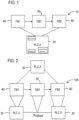
- a traditional PLC automation program 10 including FBs 40 and a DB 30 is shown.
- DB1 30 is the interface between FB1 40 and FB2 40 such that the data is exchanged between FB1 40 and FB 2 40 through DB1 30.
- This traditional approach forces the automation program 10 consisting of FB1->DB1->FB2 to be allocated to a specific hardware configuration (e.g. PLC A 20).
- PLC programmable logic controller
- the term programmable logic controller (PLC) as used herein refers to industrial computer control system that monitors the state of input devices and makes decisions based upon custom program instructions, typically located in a function/function block, to control the state of output devices.
- the PCL may include an operating system, firmware, and a processor.
- the QB 50 is an explicit communication primitive (queue) that may be addressed by the automation program as if it were a DB.
- QB1 50 replaces the DB1 30 of the automation program 10.
- a QB can decouple the execution from the communication. So, for example, with the introduction of QB 50, the same program FB1->QB1->FB2 100 may be dynamically allocated during runtime to various hardware configurations such as to a single PLC, e.g., PLC A 20, as in the original program shown in Fig.
- the QB exists in the runtime of the PLC.
- the QB 50 may be implemented in the firmware of the PLC. Alternately, the QB 50 may be implemented in the operating system of the PLC.
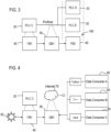
- the QBs 50 enable high-availability and high redundancy configurations as shown in Fig. 3 .
- the QB 50 may dynamically allocate the automation program FB1->QB1->FB2 100 to a plurality of programmable logic controllers PLC C 20, PLC D 20, and PLC E 20 during runtime.
- the QBs 50 may be implemented utilizing messaging queues or message passing libraries such as ZeroMQ or RabbitMQ. Different communication patterns may be utilized by the QBs 50 depending on the source of the data to be exchanged, the configuration of PLCs, or the platforms used by the PLCs, for example. Either a programmer having knowledge of the specific application implemented or the runtime system while monitoring the state of the system may choose the communication pattern used. Additionally, depending on this state of the system/network, different communication patterns may be chosen to accomplish faster execution time, lower cycle time, etc. For example, the QBs 50 may offer the following different communication patterns:
- the message queuing capability of the QBs enable IoT communication as shown in Fig. 4 utilizing a communication pattern such as the publish-subscribe communication pattern.
- the publish-subscribe communication pattern is a messaging pattern where senders of messages, called publishers, do not program the messages to be sent directly to specific receivers, called subscribers, but instead categorize published messages into classes without knowledge of which subscribers, if any, there may be.
- subscribers express interest in one or more classes and only receive messages that are of interest, without knowledge of which publishers, if any, there are.
- a sensor value from a sensor 60 in the automation environment may be published by FB 1 40 utilizing QB1 50 to data consumers, i.e., subscribers, that are authorized to read the value from the internet 70.
- the data consumers in this example may be non-PLC applications 80 written in different languages such as C, C++, Python, Java, etc.
- QBs 50 multi-platform compatibility may be achieved. While a sensor value has been used in the exemplary embodiment, other values from further IoT devices may also be exchanged in the described manner.
- the QB enables parallel and distributed computation patterns in the automation network. This will greatly benefit new applications that demand higher processing in the edge, as close to sensors 60, as possible.
- the function block FB 1 40 allocated to PLC C 20 needs a computation on a sensor value from sensor 60 but FB1 40 does not have the computational capacity to get a result before a deadline.
- QB1 50 utilizes the Request-Reply communication pattern of its messaging queue to allow more powerful PLCs 20 to perform the computation on FB2 40.
- QB 1 50 sends a request to a pool of PLCs 90, PLC C, PLC E, and PLC F. Because these PLCs may be performing other tasks, the first one to read the sent message and is able to execute the computation responds to the request and sends the result back to FB 1 40 before the deadline is missed.
- Fig. 6 illustrates another example of the distributed and parallel processing capability of an automation system utilizing QBs 50.
- a complex computation is split into two PLCs, PLC D 20 and PLC E 20. using the Map-Reduce communication pattern from the messaging queue.
- the Map Reduce Communication Pattern includes a mapping function which performs filtering and/or sorting of the input data into tasks. Then, the reduce function performs a summary operation.
- a complex computation on a sensor value from sensor 60 may be split into two PLCs, PLC D 20, and PLC E 20. After the FB2 40 of PLC D 20 and PLC E 20 finishes their part of the computation, the results may be gathered for final processing in FB3 40.
- Queue blocks offer many advantages over the traditional inflexible data block.
- QBs enable multi-platform implementations of automation networks wherein PLCs can freely communicate with one another and to other non-PLC applications. Programs from one PLC can be easily migrated to other PLCs because they are no longer bound to a specific hardware.
- the queue blocks allow for parallel and distributed processing by utilizing message queues of the QBs. New nodes may be added or removed as the computation demand arises. Automation engineering programs, by utilizing queue blocks, and now dynamically exchange data with the result that they are no longer fixed to a particular configuration but can adapt to different runtime conditions.
- queue blocks offer flexibility in the automation system so that data may be easily exchanged between PLCs as well as non-PLC applications.
Landscapes
- Physics & Mathematics (AREA)
- General Physics & Mathematics (AREA)
- Engineering & Computer Science (AREA)
- Automation & Control Theory (AREA)
- Programmable Controllers (AREA)
Claims (11)
- System zum Austauschen von Daten zwischen einer ersten programmierbaren Logiksteuereinheit (20) und einem Datenverbraucher (20, 40, 80) in einer Automatisierungsumgebung (10), das Folgendes umfasst:
die erste programmierbare Logiksteuereinheit (20); undeinen Warteschlangenblock (50), der für die erste programmierbare Logiksteuereinheit (20) implementiert ist, wobei der Warteschlangenblock (50) in der Laufzeit der ersten programmierbaren Logiksteuereinheit (20) vorhanden ist, wobei der Warteschlangenblock (50) ein austauschbarer Datentyp in der ersten programmierbaren Logiksteuereinheit (20) ist, um einen Datenblocktyp zu ersetzen;wobei Programmanweisungen, die durch die erste programmierbare Logiksteuereinheit (20) ausführbar sind, innerhalb eines ersten Funktionsblocks (40) innerhalb der ersten programmierbaren Logiksteuereinheit (20) implementiert sind, wobei der Funktionsblock (40) konfiguriert ist, den Warteschlangenblock (50) anstelle eines Datenblocks (30) zu verwenden;wobei der erste Funktionsblock (40) der ersten programmierbaren Logiksteuereinheit (20) über den Warteschlangenblock (50) zur Laufzeit zugeteilt wird und der Warteschlangenblock (50) konfiguriert ist, Daten zwischen dem ersten Funktionsblock (40) und dem Datenverbraucher (20, 40, 80) während der Laufzeit dynamisch auszutauschen; undwobei der Datenverbraucher (20, 40, 80) eine Anwendung (80) ist, die in einem Computersystem gehostet wird, und der Warteschlangenblock konfiguriert ist, Daten zwischen der ersten programmierbaren Logiksteuereinheit (20) und der Anwendung (80) dynamisch auszutauschen; oderwobei der Datenverbraucher (20, 40, 80) eine zweite programmierbare Logiksteuereinheit (20) mit einem zweiten Funktionsblock (40), der Programmanweisungen enthält, ist, wobei die Programmanweisungen durch die zweite programmierbare Logiksteuereinheit (20) ausführbar sind und der Warteschlangenblock konfiguriert ist, Daten zwischen der ersten programmierbaren Logiksteuereinheit (20) und der zweiten programmierbaren Logiksteuereinheit (20) durch Austauschen der Daten zwischen dem ersten Funktionsblock (40) und dem zweiten Funktionsblock (40) dynamisch auszutauschen. - System nach Anspruch 1, wobei die Anwendung (80) in einer Programmiersprache, die C, C++, Python oder Java ist, geschrieben ist.
- System nach Anspruch 1, wobei der Warteschlangenblock (50) in einer Firmware oder einem Betriebssystem der ersten programmierbaren Logiksteuereinheit (20) implementiert ist.
- System nach Anspruch 1, wobei der Warteschlangenblock (50) konfiguriert ist, den ersten Funktionsblock (40) mehreren programmierbaren Logiksteuereinheiten (20) während der Laufzeit dynamisch zuzuteilen.
- System nach Anspruch 1, wobei der Warteschlangenblock (50) ferner eine Warteschlange für eine Nachrichtenübermittlung für eine Kommunikation zwischen der ersten programmierbaren Logiksteuereinheit (20) und dem Datenverbraucher (20, 40, 80) umfasst.
- System nach Anspruch 5, wobei die Warteschlange für eine Nachrichtenübermittlung konfiguriert ist, mehrere Kommunikationsmuster, die aus der Gruppe ausgewählt sind, die aus Punkt-zu-Punkt, "Request-Reply", "Publication-Subscription", Map-Reduce", Rundfunk und Kombinationen davon besteht, zu unterstützen.
- System nach Anspruch 6, wobei ein Datenwert zwischen den Programmanweisungen der ersten programmierbaren Logiksteuereinheit (20) und dem Datenverbraucher (20, 40, 80), der das "Publication-Subscription"-Kommunikationsmuster der Warteschlange für eine Nachrichtenübermittlung verwendet, über das Internet (70) ausgetauscht wird, wobei die Warteschlange für eine Nachrichtenübermittlung konfiguriert ist, den Datenwert für abonnierte Kunden, die autorisiert sind, den Datenwert von dem Internet (70) zu lesen, zu veröffentlichen.
- System nach Anspruch 7, wobei der erste Funktionsblock (40) konfiguriert ist, den Datenwert, der einen Wert von einer IoT-Vorrichtung (60) repräsentiert, zu empfangen.
- System nach Anspruch 8, wobei der erste Funktionsblock (40) konfiguriert ist, den Datenwert von einer IoT-Vorrichtung (60), die einen Sensor innerhalb der Automatisierungsumgebung (10) repräsentiert, zu empfangen.
- System nach Anspruch 5, wobei der Warteschlangenblock (50) konfiguriert ist, eine komplexe Berechnung für mehrere programmierbare Logiksteuereinheiten (20) über die Warteschlange für eine Nachrichtenübermittlung aufzuteilen, um eine parallele und verteilte Berechnung in der programmierbaren Logiksteuereinheit (20) zu erlauben.
- Computerimplementiertes Verfahren, um Daten zwischen einer ersten programmierbaren Logiksteuereinheit (20) und einem Datenverbraucher (20, 40, 80) in einer Automatisierungsumgebung (10) auszutauschen, wobei Programmanweisungen, die durch die erste programmierbare Logiksteuereinheit (20) ausführbar sind, innerhalb eines ersten Funktionsblocks (40) innerhalb der ersten programmierbaren Logiksteuereinheit (20) implementiert sind,
wobei das Verfahren Folgendes umfasst:Bereitstellen eines Warteschlangenblocks (50), um Daten zwischen dem ersten Funktionsblock (40) und dem Datenverbraucher (20, 40, 80) dynamisch auszutauschen, wobei der Warteschlangenblock (50) für die erste programmierbare Logiksteuereinheit implementiert ist, wobei der Warteschlangenblock (50) in der Laufzeit der ersten programmierbaren Logiksteuereinheit (20) vorhanden ist, wobei der Warteschlangenblock (50) ein austauschbarer Datentyp in der ersten programmierbaren Logiksteuereinheit (20) ist, um einen Datenblocktyp zu ersetzen, wobei der erste Funktionsblock (40) konfiguriert ist, den Warteschlangenblock (50) anstelle eines Datenblocks (30) zu verwenden;Zuteilen des ersten Funktionsblocks (40) zu der ersten programmierbaren Logiksteuereinheit (20) über den Warteschlangenblock (50) zur Laufzeit; unddynamisches Austauschen von Daten zwischen dem ersten Funktionsblock (40) und dem Datenverbraucher (20, 40, 80) während der Laufzeit;wobei der Datenverbraucher (20, 40, 80) eine Anwendung (80) ist, die in einem Computersystem gehostet wird, und der Warteschlangenblock Daten zwischen der ersten programmierbaren Logiksteuereinheit (20) und der Anwendung (80) dynamisch austauscht; oderwobei der Datenverbraucher (20, 40, 80) eine zweite programmierbare Logiksteuereinheit (20) mit einem zweiten Funktionsblock (40), der Programmanweisungen enthält, ist, wobei die Programmanweisungen durch die zweite programmierbare Logiksteuereinheit (20) ausführbar sind und der Warteschlangenblock Daten zwischen der ersten programmierbaren Logiksteuereinheit (20) und der zweiten programmierbaren Logiksteuereinheit (20) durch Austauschen der Daten zwischen dem ersten Funktionsblock (40) und dem zweiten Funktionsblock (40) dynamisch austauscht.
Applications Claiming Priority (1)
| Application Number | Priority Date | Filing Date | Title |
|---|---|---|---|
| PCT/US2019/051817 WO2021054954A1 (en) | 2019-09-19 | 2019-09-19 | Queue blocks for flexible automation engineering programs |
Publications (3)
| Publication Number | Publication Date |
|---|---|
| EP4014096A1 EP4014096A1 (de) | 2022-06-22 |
| EP4014096C0 EP4014096C0 (de) | 2024-12-25 |
| EP4014096B1 true EP4014096B1 (de) | 2024-12-25 |
Family
ID=68104793
Family Applications (1)
| Application Number | Title | Priority Date | Filing Date |
|---|---|---|---|
| EP19780103.8A Active EP4014096B1 (de) | 2019-09-19 | 2019-09-19 | Queue blocks für flexible automatisierungstechnik |
Country Status (4)
| Country | Link |
|---|---|
| US (1) | US12321147B2 (de) |
| EP (1) | EP4014096B1 (de) |
| CN (1) | CN114503037B (de) |
| WO (1) | WO2021054954A1 (de) |
Families Citing this family (3)
| Publication number | Priority date | Publication date | Assignee | Title |
|---|---|---|---|---|
| CN116048383B (zh) * | 2022-11-01 | 2025-12-12 | 中控技术股份有限公司 | 基于不可信opc服务的写稳定方法和系统 |
| WO2026016003A1 (zh) * | 2024-07-15 | 2026-01-22 | 西门子股份公司 | 可编程逻辑控制器的通信方法、系统、电子设备及介质 |
| EP4715500A1 (de) * | 2024-09-19 | 2026-03-25 | Siemens Aktiengesellschaft | Verfahren und system zur verwaltung von ereignissen in einem netzwerk aus speicherprogrammierbaren steuerungen unter verwendung von maschinellem lernen |
Family Cites Families (18)
| Publication number | Priority date | Publication date | Assignee | Title |
|---|---|---|---|---|
| FR2811183B1 (fr) * | 2000-06-30 | 2006-09-01 | Schneider Automation | Bloc fonction web dans un equipement d'automatisme |
| US20020124011A1 (en) * | 2001-03-01 | 2002-09-05 | Baxter Robert W. | Methods, systems, and computer program products for communicating with a controller using a database interface |
| JP3963174B2 (ja) * | 2003-03-14 | 2007-08-22 | オムロン株式会社 | 表示・編集装置及び表示方法並びにプログラム |
| US7269468B2 (en) * | 2003-09-05 | 2007-09-11 | Fisher-Rosemount Systems, Inc. | State machine function block with a user modifiable output configuration database |
| US7206899B2 (en) | 2003-12-29 | 2007-04-17 | Intel Corporation | Method, system, and program for managing data transfer and construction |
| JP4442524B2 (ja) * | 2005-07-12 | 2010-03-31 | 株式会社ジェイテクト | 安全plc |
| US8255065B2 (en) | 2008-05-05 | 2012-08-28 | Siemens Aktiengesellschaft | Mobile function block for a PLC based distributed control system |
| JP5168012B2 (ja) * | 2008-07-28 | 2013-03-21 | 株式会社ジェイテクト | プログラマブルコントローラのプログラム編集装置 |
| US8166237B1 (en) * | 2009-10-23 | 2012-04-24 | Altera Corporation | Configurable allocation of thread queue resources in an FPGA |
| WO2013113320A1 (en) * | 2012-01-31 | 2013-08-08 | Abb Technology Ag | System for modifying a plc program |
| CN103901808A (zh) | 2012-12-26 | 2014-07-02 | 施耐德电器工业公司 | 在可编程逻辑控制器中实现可编程实时逻辑的方法及系统 |
| CN103235549B (zh) | 2013-04-08 | 2015-09-23 | 北京信息科技大学 | 可编程序控制器应用程序的自动生成方法及装置 |
| US9575807B2 (en) * | 2014-04-15 | 2017-02-21 | Intel Corporation | Processing accelerator with queue threads and methods therefor |
| US10496067B2 (en) | 2015-08-07 | 2019-12-03 | Siemens Aktiengesellschaft | Automation and control distributed data management systems |
| KR101923100B1 (ko) | 2015-12-10 | 2018-11-28 | 지멘스 악티엔게젤샤프트 | Plc 히스토리언과 통합된 분산 임베디드 데이터 및 지식 관리 시스템 |
| CN106502817A (zh) | 2016-10-26 | 2017-03-15 | 努比亚技术有限公司 | 一种处理数据的方法和终端 |
| DE102019123271A1 (de) * | 2019-08-30 | 2021-03-04 | Phoenix Contact Gmbh & Co. Kg | Verfahren und industrielle Steuerung zum sychronisierten Aufrufen eines Funktionsbausteins in einem Steuerungsprogamm mit OPC UA |
| CN114556241B (zh) * | 2019-10-14 | 2024-05-07 | 西门子股份公司 | 将人工智能(ai)集成到自动化中的可编程逻辑控制器(plc)程序中功能块的ai伴侣 |
-
2019
- 2019-09-19 EP EP19780103.8A patent/EP4014096B1/de active Active
- 2019-09-19 WO PCT/US2019/051817 patent/WO2021054954A1/en not_active Ceased
- 2019-09-19 US US17/641,680 patent/US12321147B2/en active Active
- 2019-09-19 CN CN201980100523.4A patent/CN114503037B/zh active Active
Also Published As
| Publication number | Publication date |
|---|---|
| CN114503037A (zh) | 2022-05-13 |
| EP4014096C0 (de) | 2024-12-25 |
| US20220299967A1 (en) | 2022-09-22 |
| WO2021054954A1 (en) | 2021-03-25 |
| US12321147B2 (en) | 2025-06-03 |
| CN114503037B (zh) | 2024-12-27 |
| EP4014096A1 (de) | 2022-06-22 |
Similar Documents
| Publication | Publication Date | Title |
|---|---|---|
| Goldschmidt et al. | Container-based architecture for flexible industrial control applications | |
| US10365626B2 (en) | Extending the functionality of a programmable logic controller (PLC) with apps without changing the PLC programming | |
| RU2487388C2 (ru) | Исполнительный механизм для систем hvac и способ его функционирования | |
| US11061377B2 (en) | Control device | |
| JP7467660B2 (ja) | 産業用オートメーションプラットフォームのオートメーションプログラムを管理する方法および装置 | |
| EP4014096B1 (de) | Queue blocks für flexible automatisierungstechnik | |
| WO2005109299A1 (en) | Robot control software framework in open distributed process architecture | |
| US11307550B2 (en) | Sequence control of program modules | |
| JP6978443B2 (ja) | レガシー・レベル1コントローラ仮想化システムおよび方法 | |
| US20190215192A1 (en) | Gateway and Method for Connecting a Data Source System to an IT System | |
| EP3489776B1 (de) | Steuerungsvorrichtung, steuerungsverfahren und programm | |
| Ehrlich et al. | Usage of retrofitting for migration of industrial production lines to industry 4.0 | |
| US20200278891A1 (en) | Dynamic Load Balancing In Network Centric Process Control Systems | |
| US20160094158A1 (en) | Method for power station simulation | |
| US20220318080A1 (en) | Actor-Based Framework for Communication between Software Systems Following Third-Party Failure | |
| EP4320512B1 (de) | System und verfahren zur anpassung eines rekonfigurierbaren laufzeitsystems in automatisierungssystemen | |
| JP2019139365A (ja) | アプリケーションプログラムを生成する方法、装置、プログラム | |
| Hadlich et al. | Common communication model for distributed automation systems | |
| US20210109948A1 (en) | Method of visualizing screen content on a data visualization system, and data visualization system for visualizing screen content | |
| US10078314B2 (en) | Method for providing functions within an industrial automation system, and industrial automation system | |
| JP2009531759A (ja) | 少なくとも1つのオートメーションユニットを包含する制御通信システム | |
| Plötzeneder et al. | Rethinking PLCs: Industrial Ethernet for Large-Scale Real-Time Distributed Control Applications | |
| CN120457416A (zh) | 用于更新其中包含有应用程序的容器的编排系统以及基于此的编排方法 | |
| EP3428753A1 (de) | Automatisierungssystem und -verfahren mit zyklusbasierten und ereignisbasierten automatisierungsvorrichtungen | |
| Thate et al. | Methods for Interfacing Common Utility Services in Simulink Models Used for Production Code Generation |
Legal Events
| Date | Code | Title | Description |
|---|---|---|---|
| STAA | Information on the status of an ep patent application or granted ep patent |
Free format text: STATUS: UNKNOWN |
|
| STAA | Information on the status of an ep patent application or granted ep patent |
Free format text: STATUS: THE INTERNATIONAL PUBLICATION HAS BEEN MADE |
|
| PUAI | Public reference made under article 153(3) epc to a published international application that has entered the european phase |
Free format text: ORIGINAL CODE: 0009012 |
|
| STAA | Information on the status of an ep patent application or granted ep patent |
Free format text: STATUS: REQUEST FOR EXAMINATION WAS MADE |
|
| 17P | Request for examination filed |
Effective date: 20220317 |
|
| AK | Designated contracting states |
Kind code of ref document: A1 Designated state(s): AL AT BE BG CH CY CZ DE DK EE ES FI FR GB GR HR HU IE IS IT LI LT LU LV MC MK MT NL NO PL PT RO RS SE SI SK SM TR |
|
| DAV | Request for validation of the european patent (deleted) | ||
| DAX | Request for extension of the european patent (deleted) | ||
| STAA | Information on the status of an ep patent application or granted ep patent |
Free format text: STATUS: EXAMINATION IS IN PROGRESS |
|
| 17Q | First examination report despatched |
Effective date: 20230118 |
|
| GRAP | Despatch of communication of intention to grant a patent |
Free format text: ORIGINAL CODE: EPIDOSNIGR1 |
|
| STAA | Information on the status of an ep patent application or granted ep patent |
Free format text: STATUS: GRANT OF PATENT IS INTENDED |
|
| INTG | Intention to grant announced |
Effective date: 20240715 |
|
| GRAS | Grant fee paid |
Free format text: ORIGINAL CODE: EPIDOSNIGR3 |
|
| GRAA | (expected) grant |
Free format text: ORIGINAL CODE: 0009210 |
|
| STAA | Information on the status of an ep patent application or granted ep patent |
Free format text: STATUS: THE PATENT HAS BEEN GRANTED |
|
| AK | Designated contracting states |
Kind code of ref document: B1 Designated state(s): AL AT BE BG CH CY CZ DE DK EE ES FI FR GB GR HR HU IE IS IT LI LT LU LV MC MK MT NL NO PL PT RO RS SE SI SK SM TR |
|
| REG | Reference to a national code |
Ref country code: GB Ref legal event code: FG4D |
|
| REG | Reference to a national code |
Ref country code: CH Ref legal event code: EP |
|
| REG | Reference to a national code |
Ref country code: DE Ref legal event code: R096 Ref document number: 602019063986 Country of ref document: DE |
|
| REG | Reference to a national code |
Ref country code: IE Ref legal event code: FG4D |
|
| U01 | Request for unitary effect filed |
Effective date: 20241225 |
|
| U07 | Unitary effect registered |
Designated state(s): AT BE BG DE DK EE FI FR IT LT LU LV MT NL PT RO SE SI Effective date: 20250110 |
|
| PG25 | Lapsed in a contracting state [announced via postgrant information from national office to epo] |
Ref country code: HR Free format text: LAPSE BECAUSE OF FAILURE TO SUBMIT A TRANSLATION OF THE DESCRIPTION OR TO PAY THE FEE WITHIN THE PRESCRIBED TIME-LIMIT Effective date: 20241225 |
|
| PG25 | Lapsed in a contracting state [announced via postgrant information from national office to epo] |
Ref country code: NO Free format text: LAPSE BECAUSE OF FAILURE TO SUBMIT A TRANSLATION OF THE DESCRIPTION OR TO PAY THE FEE WITHIN THE PRESCRIBED TIME-LIMIT Effective date: 20250325 |
|
| PG25 | Lapsed in a contracting state [announced via postgrant information from national office to epo] |
Ref country code: GR Free format text: LAPSE BECAUSE OF FAILURE TO SUBMIT A TRANSLATION OF THE DESCRIPTION OR TO PAY THE FEE WITHIN THE PRESCRIBED TIME-LIMIT Effective date: 20250326 |
|
| PG25 | Lapsed in a contracting state [announced via postgrant information from national office to epo] |
Ref country code: RS Free format text: LAPSE BECAUSE OF FAILURE TO SUBMIT A TRANSLATION OF THE DESCRIPTION OR TO PAY THE FEE WITHIN THE PRESCRIBED TIME-LIMIT Effective date: 20250325 |
|
| PG25 | Lapsed in a contracting state [announced via postgrant information from national office to epo] |
Ref country code: SM Free format text: LAPSE BECAUSE OF FAILURE TO SUBMIT A TRANSLATION OF THE DESCRIPTION OR TO PAY THE FEE WITHIN THE PRESCRIBED TIME-LIMIT Effective date: 20241225 |
|
| PG25 | Lapsed in a contracting state [announced via postgrant information from national office to epo] |
Ref country code: PL Free format text: LAPSE BECAUSE OF FAILURE TO SUBMIT A TRANSLATION OF THE DESCRIPTION OR TO PAY THE FEE WITHIN THE PRESCRIBED TIME-LIMIT Effective date: 20241225 |
|
| PG25 | Lapsed in a contracting state [announced via postgrant information from national office to epo] |
Ref country code: ES Free format text: LAPSE BECAUSE OF FAILURE TO SUBMIT A TRANSLATION OF THE DESCRIPTION OR TO PAY THE FEE WITHIN THE PRESCRIBED TIME-LIMIT Effective date: 20241225 |
|
| PG25 | Lapsed in a contracting state [announced via postgrant information from national office to epo] |
Ref country code: IS Free format text: LAPSE BECAUSE OF FAILURE TO SUBMIT A TRANSLATION OF THE DESCRIPTION OR TO PAY THE FEE WITHIN THE PRESCRIBED TIME-LIMIT Effective date: 20250425 |
|
| PG25 | Lapsed in a contracting state [announced via postgrant information from national office to epo] |
Ref country code: SK Free format text: LAPSE BECAUSE OF FAILURE TO SUBMIT A TRANSLATION OF THE DESCRIPTION OR TO PAY THE FEE WITHIN THE PRESCRIBED TIME-LIMIT Effective date: 20241225 |
|
| PG25 | Lapsed in a contracting state [announced via postgrant information from national office to epo] |
Ref country code: CZ Free format text: LAPSE BECAUSE OF FAILURE TO SUBMIT A TRANSLATION OF THE DESCRIPTION OR TO PAY THE FEE WITHIN THE PRESCRIBED TIME-LIMIT Effective date: 20241225 |
|
| U20 | Renewal fee for the european patent with unitary effect paid |
Year of fee payment: 7 Effective date: 20250919 |
|
| PLBE | No opposition filed within time limit |
Free format text: ORIGINAL CODE: 0009261 |
|
| STAA | Information on the status of an ep patent application or granted ep patent |
Free format text: STATUS: NO OPPOSITION FILED WITHIN TIME LIMIT |
|
| 26N | No opposition filed |
Effective date: 20250926 |