EP4014590B1 - Procédé et appareil d'adaptation de surveillance de pdcch - Google Patents
Procédé et appareil d'adaptation de surveillance de pdcch Download PDFInfo
- Publication number
- EP4014590B1 EP4014590B1 EP20852534.5A EP20852534A EP4014590B1 EP 4014590 B1 EP4014590 B1 EP 4014590B1 EP 20852534 A EP20852534 A EP 20852534A EP 4014590 B1 EP4014590 B1 EP 4014590B1
- Authority
- EP
- European Patent Office
- Prior art keywords
- serving cell
- cell
- group
- serving
- dormant behavior
- Prior art date
- Legal status (The legal status is an assumption and is not a legal conclusion. Google has not performed a legal analysis and makes no representation as to the accuracy of the status listed.)
- Active
Links
Images



Classifications
-
- H—ELECTRICITY
- H04—ELECTRIC COMMUNICATION TECHNIQUE
- H04L—TRANSMISSION OF DIGITAL INFORMATION, e.g. TELEGRAPHIC COMMUNICATION
- H04L5/00—Arrangements affording multiple use of the transmission path
- H04L5/003—Arrangements for allocating sub-channels of the transmission path
- H04L5/0053—Allocation of signalling, i.e. of overhead other than pilot signals
-
- H—ELECTRICITY
- H04—ELECTRIC COMMUNICATION TECHNIQUE
- H04W—WIRELESS COMMUNICATION NETWORKS
- H04W72/00—Local resource management
- H04W72/20—Control channels or signalling for resource management
- H04W72/23—Control channels or signalling for resource management in the downlink direction of a wireless link, i.e. towards a terminal
-
- H—ELECTRICITY
- H04—ELECTRIC COMMUNICATION TECHNIQUE
- H04L—TRANSMISSION OF DIGITAL INFORMATION, e.g. TELEGRAPHIC COMMUNICATION
- H04L5/00—Arrangements affording multiple use of the transmission path
- H04L5/0001—Arrangements for dividing the transmission path
- H04L5/0003—Two-dimensional division
- H04L5/0005—Time-frequency
- H04L5/0007—Time-frequency the frequencies being orthogonal, e.g. OFDM(A) or DMT
- H04L5/001—Time-frequency the frequencies being orthogonal, e.g. OFDM(A) or DMT the frequencies being arranged in component carriers
-
- H—ELECTRICITY
- H04—ELECTRIC COMMUNICATION TECHNIQUE
- H04L—TRANSMISSION OF DIGITAL INFORMATION, e.g. TELEGRAPHIC COMMUNICATION
- H04L5/00—Arrangements affording multiple use of the transmission path
- H04L5/0091—Signalling for the administration of the divided path, e.g. signalling of configuration information
- H04L5/0096—Indication of changes in allocation
- H04L5/0098—Signalling of the activation or deactivation of component carriers, subcarriers or frequency bands
-
- H—ELECTRICITY
- H04—ELECTRIC COMMUNICATION TECHNIQUE
- H04W—WIRELESS COMMUNICATION NETWORKS
- H04W24/00—Supervisory, monitoring or testing arrangements
- H04W24/10—Scheduling measurement reports ; Arrangements for measurement reports
-
- H—ELECTRICITY
- H04—ELECTRIC COMMUNICATION TECHNIQUE
- H04W—WIRELESS COMMUNICATION NETWORKS
- H04W76/00—Connection management
- H04W76/20—Manipulation of established connections
- H04W76/27—Transitions between radio resource control [RRC] states
-
- H—ELECTRICITY
- H04—ELECTRIC COMMUNICATION TECHNIQUE
- H04W—WIRELESS COMMUNICATION NETWORKS
- H04W76/00—Connection management
- H04W76/20—Manipulation of established connections
- H04W76/28—Discontinuous transmission [DTX]; Discontinuous reception [DRX]
-
- H—ELECTRICITY
- H04—ELECTRIC COMMUNICATION TECHNIQUE
- H04W—WIRELESS COMMUNICATION NETWORKS
- H04W24/00—Supervisory, monitoring or testing arrangements
- H04W24/08—Testing, supervising or monitoring using real traffic
-
- H—ELECTRICITY
- H04—ELECTRIC COMMUNICATION TECHNIQUE
- H04W—WIRELESS COMMUNICATION NETWORKS
- H04W52/00—Power management, e.g. Transmission Power Control [TPC] or power classes
- H04W52/02—Power saving arrangements
- H04W52/0209—Power saving arrangements in terminal devices
- H04W52/0225—Power saving arrangements in terminal devices using monitoring of external events, e.g. the presence of a signal
- H04W52/0229—Power saving arrangements in terminal devices using monitoring of external events, e.g. the presence of a signal where the received signal is a wanted signal
-
- H—ELECTRICITY
- H04—ELECTRIC COMMUNICATION TECHNIQUE
- H04W—WIRELESS COMMUNICATION NETWORKS
- H04W52/00—Power management, e.g. Transmission Power Control [TPC] or power classes
- H04W52/02—Power saving arrangements
- H04W52/0209—Power saving arrangements in terminal devices
- H04W52/0225—Power saving arrangements in terminal devices using monitoring of external events, e.g. the presence of a signal
- H04W52/0229—Power saving arrangements in terminal devices using monitoring of external events, e.g. the presence of a signal where the received signal is a wanted signal
- H04W52/0235—Power saving arrangements in terminal devices using monitoring of external events, e.g. the presence of a signal where the received signal is a wanted signal where the received signal is a power saving command
-
- Y—GENERAL TAGGING OF NEW TECHNOLOGICAL DEVELOPMENTS; GENERAL TAGGING OF CROSS-SECTIONAL TECHNOLOGIES SPANNING OVER SEVERAL SECTIONS OF THE IPC; TECHNICAL SUBJECTS COVERED BY FORMER USPC CROSS-REFERENCE ART COLLECTIONS [XRACs] AND DIGESTS
- Y02—TECHNOLOGIES OR APPLICATIONS FOR MITIGATION OR ADAPTATION AGAINST CLIMATE CHANGE
- Y02D—CLIMATE CHANGE MITIGATION TECHNOLOGIES IN INFORMATION AND COMMUNICATION TECHNOLOGIES [ICT], I.E. INFORMATION AND COMMUNICATION TECHNOLOGIES AIMING AT THE REDUCTION OF THEIR OWN ENERGY USE
- Y02D30/00—Reducing energy consumption in communication networks
- Y02D30/70—Reducing energy consumption in communication networks in wireless communication networks
Definitions
- the present disclosure generally relates to wireless communication, and more particularly, to Physical Downlink Control Channel (PDCCH) monitoring and adaptation in next generation wireless communication networks.
- PDCCH Physical Downlink Control Channel
- CA Carrier Aggregation
- UE User Equipment
- SFN System Frame Number
- DL Downlink
- UL Uplink
- the gNB configures the UE with UL and DL Bandwidth Part(s) (BWPs).
- BWPs Bandwidth Part(s)
- SCells Secondary Cells
- the gNB configures the UE with DL BWP(s) at least (i.e., there may be none in the UL).
- the initial BWP is the BWP used for initial access.
- the initial BWP is the BWP configured for the UE to first operate at SCell activation.
- the receive and transmit bandwidth of a UE need not be as large as the bandwidth of the cell and can be adjusted: the width can be ordered to change (e.g., to shrink during period of low activity to save power); the location can move in the frequency domain (e.g., to increase scheduling flexibility); and the subcarrier spacing can be ordered to change (e.g., to allow different services).
- a subset of the total cell bandwidth of a cell is referred to as a BWP and BA is achieved by configuring the UE with BWP(s) and telling the UE which of the configured BWPs is currently the active one.
- a UE configured for operation in BWPs of a serving cell is configured by higher layers for the serving cell.
- a set of at most four BWPs for UE reception are identified in a DL bandwidth by the parameter BWP-Downlink
- a set of at most four BWPs for UE transmission are identified in an UL bandwidth by the parameter BWP-Uplink.
- Each DL BWP of the cell may or may not be configured with a PDCCH configuration (i.e., the configuration of the PDCCH for the BWP is optional).
- an activation/deactivation mechanism of Cells is supported.
- the UE When an SCell is deactivated, the UE does not need to receive the corresponding PDCCH or Physical Downlink Shared Channel (PDSCH), cannot transmit in the corresponding uplink, nor is it required to perform Channel Quality Indicator (CQI) measurements.
- the UE shall receive PDSCH and PDCCH configurations (if the UE is configured to monitor PDCCH on this SCell) and is expected to be able to perform CQI measurements.
- a UE may be configured with a Discontinuous Reception (DRX) functionality that controls the UE's PDCCH monitoring activity.
- DRX Discontinuous Reception
- the UE shall also monitor PDCCH according to requirements found in other subclauses of the 3GPP Medium Access Control (MAC) protocol specification.
- MAC Medium Access Control
- RRC_CONNECTED if a DRX is configured, for all the activated Serving Cells, the UE may monitor the PDCCH discontinuously using the DRX operation specified in this subclause; otherwise the UE shall monitor the PDCCH as specified in the 3GPP Radio Resource Control (RRC) protocol specification.
- RRC Radio Resource Control
- DRX is characterized by the following conditions:
- the Active Time includes the time while:
- SCells may be used to offload large data bursts, which can help increase UE's link throughput, but at the same time increase UE's power consumption. Therefore, to enable reasonable UE battery consumption when CA is configured, some methods may be applied by a network (NW).
- NW could deactivate the configured SCells by a SCell Activation/Deactivation MAC Control Element (CE).
- CE SCell Activation/Deactivation MAC Control Element
- the UE may not: transmit Sounding Reference Signal (SRS) on the SCell, report Channel State Information (CSI) for the SCell, transmit on uplink shared channel (UL-SCH) on the SCell, transmit on Random Access Channel (RACH) on the SCell, monitor the PDCCH on the SCell, monitor the PDCCH for the SCell, and/or transmit PUCCH on the SCell.
- SRS Sounding Reference Signal
- CSI Channel State Information
- UL-SCH uplink shared channel
- RACH Random Access Channel
- monitor the PDCCH on the SCell monitor the PDCCH for the SCell
- the drawback is a long delay for CQI measurement and/or CQI report at the beginning when the SCell is re-activated, which may degrade the efficiency.
- the UE may need to monitor PDCCH on each of the serving cells with a PDCCH configuration. It is well known that even if the UE is not scheduled with data on a SCell, a large percentage of power is spent on that cell for monitoring PDCCH on the cell. Therefore, it would be very useful if a UE can dynamically adapt its PDCCH monitoring on a SCell, e.g., based on its traffic load. In one current method, a NW could de-configure the PDCCH on the SCell.
- the UE may not need to monitor the PDCCH on the SCell. If the NW would like to schedule the transmission on the SCell, the NW may signal the PDCCH via another cell for the SCell (e.g., based on cross-carrier scheduling). However, for this alternative, to reconfigure the RRC configuration is not time efficient, which may typically take a long time to change the configuration.
- some enhancements for dynamically adapting PDCCH monitoring to reduce PDCCH monitoring on a specific serving cell(s) or a specific cell group may be beneficial for power saving.
- Document US 2019/200413 A1 discloses a method and an apparatus for changing or controlling a state of a secondary cell in carrier aggregation.
- the method includes receiving secondary cell (SCell) state indication information indicating a state for a SCell from a base station through an RRC message or an MAC control element, causing a state of the SCell to transition into a dormant state when the SCell state indication information indicates the dormant state, and transmitting channel state information reporting for the SCell in the dormant state according to an dormant state CQI report period parameter set separately from an activation state CQI report period parameter.
- SCell secondary cell
- A-CQI aperiodic channel quality indicator
- SCell Secondary Cell
- LTE Long Term Evolution
- a User Equipment receives a request for reporting A-CQI relating to a Scell configured for the UE when the UE is in a first state corresponding to the Scell, the first state designed for a reduced SCell activation latency and to result in the UE using lower power as compared to when the UE is in a second state.
- the UE in response to the request, reports the A-CQI for the Scell in accordance with a first A-CQI reporting configuration for the first state which is different from a second A-CQI reporting configuration for the second state.
- a method performed by a UE configured with a plurality of serving cells includes receiving, through RRC signaling from a BS, an indication indicating a dormancy cell group having a first serving cell and a second serving cell of the plurality of serving cells.
- the UE also receives, from the BS, a first indicator indicating to the UE that a dormant behavior to the first serving cell of the dormancy cell group is to be activated when the first serving cell is activated, the dormant behavior including stopping monitoring a PDCCH of the first serving cell.
- the UE also receives, from the BS, a second indicator indicating to the UE that a dormant behavior to the second serving cell of the dormancy cell group is to be deactivated when the second serving cell is activated, the dormant behavior including stopping monitoring a PDCCH of the second serving cell.
- the UE also receives, through Media Access Control (MAC) signaling from the BS, a cell activation indication to activate the first serving cell and the second serving cell.
- MAC Media Access Control
- the first serving cell and the second serving cell are activated based on the cell activation indication, the dormant behavior to the first serving cell is applied based on the first indicator when the first serving cell is activated, and the dormant behavior to the second serving cell is not applied based on the second indicator when the second serving cell is activated.
- the first indicator and the second indicator may each indicate an initial dormant behavior to be activated or deactivated when the corresponding first and second serving cells are activated.
- the UE may receive, from the BS, a wake up signal indicating a group dormant behavior of the dormancy cell group, the wake up signal further including power saving information, apply the dormant behavior to the first serving cell and the second serving cell when the wake up signal indicates the group dormant behavior for the dormancy cell group is to be activated, and not apply the dormant behavior to the first serving cell and the second serving cell when the wake up signal indicates the group dormant behavior of the dormancy cell group is to be deactivated.
- the power saving information may include a PDCCH monitoring behavior within an on-duration time of a Discontinuous Reception (DRX) mechanism, and the wake up signal may indicate the group dormant behavior for all serving cells in the dormancy cell group via a single bit.
- DRX Discontinuous Reception
- the method also includes receiving, through Physical Layer (PHY) signaling from the BS, a signal associated with a specific Downlink Control Information (DCI) format indicating a group dormant behavior of the dormancy cell group, wherein the signal indicates the group dormant behavior for all serving cells in the dormancy cell group via a single bit, applying the dormant behavior to the first serving cell and the second serving cell when the signal indicates the group dormant behavior of the dormancy cell group is to be activated, and not applying the dormant behavior to the first serving cell and the second serving cell when the signal indicates the group dormant behavior of the dormancy cell group is to be deactivated.
- PHY Physical Layer
- the method may include the dormant behavior further including at least one of performing CSI measurement, performing Automatic Gain Control (AGC), and performing beam management.
- the dormant behavior to the first serving cell may be applied on an active BWP of the first serving cell when the first serving cell is activated.
- the dormancy cell group may include only serving cells that are Secondary Cells (SCells), and the indication may indicate a serving cell of the plurality of serving cells belonging to the dormancy cell group to the UE via a cell index of the serving cell.
- SCells Secondary Cells
- a UE configured with a plurality of serving cells, includes one or more non-transitory computer-readable media having computer-executable instructions embodied thereon, at least one processor coupled to the one or more non-transitory computer-readable media, and configured to execute the computer-executable instructions.
- the computer-executable instructions are to receive, through RRC signaling from a base station (BS), an indication indicating a dormancy cell group having a first serving cell and a second serving cell of the plurality of serving cells, receive, from the BS, a first indicator indicating to the UE that a dormant behavior to the first serving cell of the dormancy cell group is to be activated when the first serving cell is activated, the dormant behavior including stopping monitoring a PDCCH of the first serving cell, receive, from the BS, a second indicator indicating to the UE that a dormant behavior to the second serving cell of the dormancy cell group is to be deactivated when the second serving cell is activated, the dormant behavior including stopping monitoring a PDCCH of the second serving cell, and receive, through MAC signaling from the BS, a cell activation indication to activate the first serving cell and the second serving cell.
- BS base station
- the first serving cell and the second serving cell are activated based on the cell activation indication, the dormant behavior to the first serving cell is applied based on the first indicator when the first serving cell is activated, and the dormant behavior to the second serving cell is not applied based on the second indicator when the second serving cell is activated.
- the first indicator and the second indicator may each indicate an initial dormant behavior to be activated or deactivated when the corresponding first and second serving cells are activated.
- the at least one processor may be further configured to execute the computer-executable instructions to: receive, from the BS, a wake up signal indicating a group dormant behavior of the dormancy cell group, the wake up signal further including power saving information, apply the dormant behavior to the first serving cell and the second serving cell when the wake up signal indicates the group dormant behavior for the dormancy cell group is to be activated, and not apply the dormant behavior to the first serving cell and the second serving cell when the wake up signal indicates the group dormant behavior of the dormancy cell group is to be deactivated.
- the power saving information may include a PDCCH monitoring behavior within an on-duration time of a DRX mechanism.
- the wake up signal indicates the group dormant behavior for all serving cells in the dormancy cell group via a single bit.
- the method may also include the at least one processor being further configured to execute the computer-executable instructions to: receive, through PHY signaling from the BS, a signal associated with a specific Downlink Control Information DCI format indicating a group dormant behavior of the dormancy cell group, wherein the signal indicates the group dormant behavior for all serving cells in the dormancy cell group via a single bit, apply the dormant behavior to the first serving cell and the second serving cell when the signal indicates the group dormant behavior of the dormancy cell group is to be activated, and not apply the dormant behavior to the first serving cell and the second serving cell when the signal indicates the group dormant behavior of the dormancy cell group is to be deactivated.
- the at least one processor being further configured to execute the computer-executable instructions to: receive, through PHY signaling from the BS, a signal associated with a specific Downlink Control Information DCI format indicating a group dormant behavior of the dormancy cell group,
- the dormant behavior may further include at least one of performing CSI measurement, performing AGC, and performing beam management.
- the dormant behavior to the first serving cell may be applied on an active BWP of the first serving cell when the first serving cell is activated.
- the dormancy cell group may include only serving cells that are Secondary Cells (SCells), and the indication may indicate a serving cell of the plurality of serving cells belonging to the dormancy cell group to the UE via a cell index of the serving cell.
- SCells Secondary Cells
- any network function(s) or algorithm(s) described in the present disclosure may be implemented by hardware, software or a combination of software and hardware. Described functions may correspond to modules may be software, hardware, firmware, or any combination thereof.
- the software implementation may comprise computer executable instructions stored on computer readable medium such as memory or other type of storage devices.
- one or more microprocessors or general purpose computers with communication processing capability may be programmed with corresponding executable instructions and carry out the described network function(s) or algorithm(s).
- the microprocessors or general purpose computers may be formed of applications specific integrated circuitry (ASIC), programmable logic arrays, and/or using one or more digital signal processor (DSPs).
- ASIC applications specific integrated circuitry
- DSPs digital signal processor
- the computer readable medium includes but is not limited to random access memory (RAM), read only memory (ROM), erasable programmable read-only memory (EPROM), electrically erasable programmable read-only memory (EEPROM), flash memory, compact disc read-only memory (CD-ROM), magnetic cassettes, magnetic tape, magnetic disk storage, or any other equivalent medium capable of storing computer-readable instructions.
- RAM random access memory
- ROM read only memory
- EPROM erasable programmable read-only memory
- EEPROM electrically erasable programmable read-only memory
- CD-ROM compact disc read-only memory
- magnetic cassettes magnetic tape
- magnetic disk storage or any other equivalent medium capable of storing computer-readable instructions.
- a radio communication network architecture e.g., a long term evolution (LTE) system, an LTE-Advanced (LTE-A) system, an LTE-Advanced Pro system, or a 5G NR or NG-RAN typically includes at least one base station, at least one UE, and one or more optional network elements that provide connection towards a network.
- the UE communicates with the network (e.g., a CN), an evolved packet core (EPC) network, an Evolved Universal Terrestrial Radio Access network (E-UTRAN), a 5G Core (5GC), or an internet), through a radio access network (RAN) established by one or more base stations.
- LTE long term evolution
- LTE-A LTE-Advanced
- LTE-A LTE-Advanced Pro
- 5G NR or NG-RAN typically includes at least one base station, at least one UE, and one or more optional network elements that provide connection towards a network.
- the UE communicates with the network (e.g.,
- a UE may include, but is not limited to, a mobile station, a mobile terminal or device, a user communication radio terminal.
- a UE may be a portable radio equipment, which includes, but is not limited to, a mobile phone, a tablet, a wearable device, a sensor, or a personal digital assistant (PDA) with wireless communication capability.
- PDA personal digital assistant
- the UE is configured to receive and transmit signals over an air interface to one or more cells in a radio access network.
- a base station may include, but is not limited to, a node B (NB) as in the UMTS, an evolved node B (eNB) as in the LTE-A, a radio network controller (RNC) as in the UMTS, a base station controller (BSC) as in the GSM/GERAN, a ng-eNB as in an E-UTRA base station in connection with the 5GC, a next generation node B (gNB) as in the 5G-RAN, and any other apparatus capable of controlling radio communication and managing radio resources within a cell.
- the base station may connect to serve the one or more UEs through a radio interface to the network.
- a base station may be configured to provide communication services according to at least one of the following radio access technologies (RATs): Worldwide Interoperability for Microwave Access (WiMAX), Global System for Mobile communications (GSM, often referred to as 2G), GSM EDGE radio access Network (GERAN), General Packet Radio Service (GRPS), Universal Mobile Telecommunication System (UMTS, often referred to as 3G) based on basic wideband-code division multiple access (W-CDMA), high-speed packet access (HSPA), LTE, LTE-A, eLTE (evolved LTE), New Radio (NR, often referred to as 5G), and/or LTE-A Pro.
- RATs radio access technologies
- WiMAX Worldwide Interoperability for Microwave Access
- GSM Global System for Mobile communications
- GERAN GSM EDGE radio access Network
- GRPS General Packet Radio Service
- UMTS Universal Mobile Telecommunication System
- W-CDMA basic wideband-code division multiple access
- HSPA high-speed packet access
- the base station is operable to provide radio coverage to a specific geographical area using a plurality of cells forming the radio access network.
- the base station supports the operations of the cells.
- Each cell is operable to provide services to at least one UE within its radio coverage. More specifically, each cell (often referred to as a serving cell) provides services to serve one or more UEs within its radio coverage, (e.g., each cell schedules the downlink and optionally uplink resources to at least one UE within its radio coverage for downlink and optionally uplink packet transmissions).
- the base station can communicate with one or more UEs in the radio communication system through the plurality of cells.
- a cell may allocate sidelink (SL) resources for supporting proximity service (ProSe) or Vehicle to Everything (V2X) service.
- Each cell may have overlapped coverage areas with other cells.
- CORESET Control Resource Set
- the serving cell may be an activated or a deactivated serving cell.
- a "Special Cell” refers to the PCell of the Master Cell Group (MCG) or the PSCell of the Secondary Cell Group (SCG) depending on if the MAC entity is associated to the MCG or the SCG, respectively. Otherwise the term Special Cell refers to the PCell.
- MCG Master Cell Group
- SCG Secondary Cell Group
- a Special Cell supports PUCCH transmission and contention-based Random Access, and is always activated.
- a DRX mechanism as discussed above is shown, including an On Duration period, in which a UE monitors PDCCH, and an Opportunity for DRX period, wherein the UE does not monitor PDCCH.
- the On Duration period and the Opportunity for DRX period collectively form a single DRX cycle.
- APPROACH 1 Grouping of cells into a specific cell group and turning on/off (e.g., activating/deactivating) the dormant behavior (e.g., stop PDCCH monitoring, performing Channel State Information (CSI) measurement, performing Automatic Gain Control (AGC), and performing beam management) of the specific cell group.
- the dormant behavior e.g., stop PDCCH monitoring, performing Channel State Information (CSI) measurement, performing Automatic Gain Control (AGC), and performing beam management
- a UE may be configured with more than one serving cell (e.g., including an SpCell and/or at least one SCell).
- the UE may monitor PDCCH on the serving cell(s) (e.g., the serving cells which are configured with PDCCH configuration), e.g., when the UE is in DRX Active Time (e.g., if the UE is configured with DRX mechanism).
- one alternative is to group the serving cells into one or multiple specific cell groups. Then the UE can determine whether or not to apply dormant behavior (e.g., stop monitor the PDCCH) on the serving cell(s) of a specific cell group (e.g., per specific cell group basis) based on a specific indication and/or certain criteria.
- dormant behavior e.g., stop PDCCH monitoring
- the dormant behavior of the serving cells in the specific cell group could be turned ON (or activated) or OFF (or deactivated).
- the dormant behavior (e.g., stop PDCCH monitoring) of each specific cell group may individually be turned ON/OFF either by gNB or the UE itself. If the dormant behavior of the specific cell group is turned ON, the UE may apply the dormant behavior (e.g., stop monitoring the PDCCH) on the serving cells in the specific cell group. Conversely, if the dormant behavior of the specific cell group is turned OFF (or deactivated), the UE may not apply dormant behavior (e.g., the UE may monitor the PDCCH) on the serving cells in the specific cell group.
- the dormant behavior of the specific cell group may individually be turned ON/OFF either by gNB or the UE itself. If the dormant behavior of the specific cell group is turned ON, the UE may apply the dormant behavior (e.g., stop monitoring the PDCCH) on the serving cells in the specific cell group. Conversely, if the dormant behavior of the specific cell group is turned
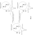
- This approach may include two steps: grouping the serving cells into a specific cell group(s), and turning ON/OFF the dormant behavior (e.g., stop PDCCH monitoring) of the specific cell group(s) based on a specific indication and/or certain criteria as illustrated in Figure 2 .
- grouping the serving cells into a specific cell group(s) and turning ON/OFF the dormant behavior (e.g., stop PDCCH monitoring) of the specific cell group(s) based on a specific indication and/or certain criteria as illustrated in Figure 2 .
- a NW may indicate whether a serving cell(s) belongs to a specific cell group (or identify which cell group the serving cell(s) belongs to) via a first indication, wherein the dormant behavior (e.g., stop PDCCH monitoring) of serving cells in the specific group could be turned ON or OFF.
- the UE may need to (always) monitor PDCCH of the serving cells which do not belong to the specific cell group.
- the first indication may be RRC signaling, MAC signaling (e.g., MAC CE), PHY signaling (e.g., DCI), a specific signaling for power saving purpose (e.g., wake-up signaling, go-to-sleep signaling, PDCCH skipping, etc.).
- the NW may (explicitly) group the serving cells into a specific cell group via RRC configuration, e.g., the information for grouping the serving cells may be included in MAC-CellGroupConfig , CellGroupConfig , PhysicalCellGroupConfig , drx-Config , servingCellConfig , servingCellConfigCommon PDCCH-ServingCellConfig , BWP-Downlink , PDCCH-config Information Element (IE) according to the 3GPP (RRC) protocol specification, etc.
- the NW may use a flag to indicate whether the corresponding serving cell is related to a specific cell group.
- NW may indicate the serving cell is related to which group (e.g., via a cell index). For example, NW may indicate a specific cell group index, and indicate the serving cells associated with the specific cell group index.
- At most one specific cell group may be configured by the gNB within an MCG/SCG (e.g., associated with one MAC entity) or within a UE.
- the first indication may only indicate whether each of the serving cell(s) (or serving SCell(s)) belongs to the specific cell group or not.
- the UE may receive the indication for a serving cell only when the serving cell belongs to the specific cell group.
- a PDCCH monitor group (PMG) indicator IE may be introduced in the RRC layer.
- a PMG IE was contained in the RRC configuration, IE specific for a serving cell (i.e., servingCell Config ), it implies the indicated serving cell belonged to the specific cell group. Conversely, when a PMG IE was not contained in the RRC configuration IE specific for a serving cell (i.e., servingCellConfig ), it implies the indicated serving cell did not belong to the specific cell group.
- the UE may receive a configuration IE to indicate which cell(s), for example, via cell index (e.g., ServCelllndex ) belongs to the specific cell group.
- cell index e.g., ServCelllndex
- each DRX configuration may be associated with one specific cell group.
- the UE may need to determine whether to monitor PDCCH on (all) the (activated) serving cells in a first cell group based on a first DRX configuration.
- the UE may need to determine whether to monitor PDCCH on (all) the (activated) serving cells in a second cell group based on a second DRX configuration.
- a NW may indicate which cell(s), for example, via cell index (e.g., ServCelllndex ) belongs to which DRX configuration via an indication.
- the NW may indicate the cell index(s) in the DRX configuration.
- the NW may indicate an index of a DRX configuration in the configuration of the serving cell.
- the serving cells may be implicitly grouped into a specific cell group.
- the cell group to which the serving cell belongs may be based on the active BWP of the serving cell. For example, if the active BWP of a first serving cell is initial or default BWP or a specific BWP, the first serving cell may belong to a first cell group. If the active BWP of a second serving cell is not initial or default or a specific BWP, the second serving cell may belong to a second cell group. If the active BWP of a first serving cell is a narrow BWP (i.e., the bandwidth is lower than a threshold), the first serving cell may belong to a first cell group.
- the active BWP of a first serving cell is initial or default BWP or a specific BWP
- the second serving cell may belong to a second cell group.
- the active BWP of a first serving cell is a narrow BWP (i.e., the bandwidth is lower than a threshold)
- the first serving cell may belong to a first cell group.
- the second serving cell may belong to a second cell group.
- the threshold is configured by the gNB via DL RRC message and may, but is not limited to, be per serving cell or serving cell group configured.
- the cell group to which the serving cell belongs may be based on the cell index. For example, if the cell index of a first serving cell is higher than a threshold, the first serving cell may belong to a first cell group. If the cell index of a second serving cell is lower than a threshold, the second serving cell may belong to a second cell group. More specifically: the threshold may be indicated in a configuration which groups serving cell(s) into a specific cell group, the threshold may be indicated in DRX configuration, the threshold may be used to indicate the UE should monitor PDCCH on which cell(s) during DRX Active time, and the threshold may be predefined in specification. It should be noted that the threshold is configured by the gNB via DL RRC message and may be, but is not limited to, being either per serving cell, or serving cell group configured.
- the cell group to which the serving cell belongs may be based on the type (e.g., SpCell, PCell, PSCell, SCell). For example, if a first serving cell is the PCell, the first serving cell may belong to a first cell group. If a second serving cell is a SCell, the second serving cell may belong to a second cell group.
- the type e.g., SpCell, PCell, PSCell, SCell.
- the group to which the serving cell belongs may be based on the characteristics of the serving cell (e.g., cells in FR1 or FR2.
- the frequency bands may be designated for different frequency ranges (FR) and 3GPP Release 15 defined them as "FR1" and "FR2"). For example, if a first serving cell is located in a first frequency range, the first serving cell may belong to a first cell group. If a second serving cell is located in a second frequency range, the second serving cell may belong to a second cell group.
- the serving cells may, but are not limited to being grouped based on one of the following examples:
- SpCell may be a first group
- the other SCells may be a second group.
- SpCell may be a first group
- some SCells may be a second group
- the remaining SCells may be a third group.
- some SCells may be a first group
- the other SCells may be a second group (e.g., SCells in FR1 may be a first group and SCells in FR2 may be a second group).
- the UE may stop monitoring PDCCH of (all) the (activated) serving cells in the specific cell group.
- the UE may need to monitor PDCCH of (all) the (activated) serving cells in the specific cell group.
- the status of the dormant behavior (e.g., stop PDCCH monitoring) of the serving cell in the specific cell group may imply whether the UE has to monitor the PDCCH on the serving cells in the specific cell group, e.g., when the UE is in DRX Active time (or DRX on duration), if the DRX is configured.
- an initial state (ON/OFF) of the dormant behavior (e.g., stop PDCCH monitoring) of a specific cell group may be configured by the NW or predefined in specification.
- the UE may determine whether to apply dormant behavior (e.g., stop monitoring PDCCH) on the serving cell based on the initial state.
- the UE may determine whether to apply dormant behavior (e.g., stop monitoring PDCCH) on the serving cells in the specific cell group based on the initial state.
- the initial state of the dormant behavior (e.g., stop PDCCH monitoring) of a specific cell group may be ON. If a serving cell associated with the specific cell group is activated, e.g., via SCell Activation/ Deactivation MAC CE, and hasn't received the second indication, the UE may stop monitoring the PDCCH on the serving cell.
- the initial state of the dormant behavior (e.g., stop PDCCH monitoring) of a specific cell group may be OFF. If a serving cell associated with the specific cell group is activated, e.g., via SCell Activation/Deactivation MAC CE, and hasn't received the second indication, the UE may monitor the PDCCH on the serving cell.
- the NW may indicate whether the status of the dormant behavior (e.g., stop PDCCH monitoring) of the specific cell group is ON/OFF via a second indication.
- the second indication may be RRC signaling, MAC signaling (e.g., MAC CE), PHY signaling (e.g., DCI), and/or a specific L1 signaling.
- the L1 signaling may be but is not limited to be for a power saving purpose (e.g., WUS, go-to-sleep signaling, PDCCH skipping, etc.).
- the second indication may indicate whether the UE should apply dormant behavior (e.g., stop monitoring PDCCH) on the serving cells of a specific cell group and/or each of specific cell groups.
- the second indication may indicate which specific cell group should apply dormant behavior (e.g., stop monitoring PDCCH).
- the UE may determine whether to apply dormant behavior (e.g., stop monitoring PDCCH) on the serving cells of a specific cell group based on the (subheader/LCID/ payload/format of the) second indication.
- the second indication may control the UE's dormant behavior (e.g., stop PDCCH monitoring behavior) for a period of time (e.g., a on duration(s), a DRX cycle(s), a duration of a (drx corresponding) timer, etc.) or until the UE receives another second indication to override the current status (e.g., ON/OFF) of dormant behavior (e.g., stop PDCCH monitoring).
- a period of time e.g., a on duration(s), a DRX cycle(s), a duration of a (drx corresponding) timer, etc.
- the second indication may control the UE's dormant behavior (e.g., stop PDCCH monitoring behavior) for a period of time and that the length of the time may be predefined in specification or preconfigured by the gNB (on per specific cell group/CG (MAC entity) basis).
- dormant behavior e.g., stop PDCCH monitoring behavior
- the length of the time may be predefined in specification or preconfigured by the gNB (on per specific cell group/CG (MAC entity) basis).
- a WUS (or a specific signaling for a power saving purpose) may be indicated at an offset (time) before the on duration of a DRX cycle.
- the UE may determine whether or not to apply the dormant behavior (e.g., stop monitoring the PDCCH) on the serving cells of the specific cell group (e.g., during the following DRX ON Duration and/or DRX cycle) based on the information included in the WUS.
- the WUS may include a field to indicate this information.
- the WUS may indicate this information based on a specific WUS configuration.
- the WUS may indicate this information based on an implicit method.
- the UE may need to apply dormant behavior (e.g., stop monitoring the PDCCH) of the specific cell group.
- dormant behavior e.g., stop monitoring the PDCCH
- a different time/frequency occasion of the WUS may imply a different status of dormant behavior.
- a DCI may indicate whether the UE should apply dormant behavior (e.g., stop monitoring PDCCH) on the serving cells of the specific cell group based on explicit or implicit ways.
- the DCI may include a field to indicate this information.
- the DCI may indicate this information based on a specific RNTI.
- the DCI may indicate this information based on a specific DCI format.
- the DCI may indicate this information based on a specific search space/CORESET, e.g., the UE receives the DCI on the specific search space/CORESET may mean the UE should/should not monitor the PDCCH of the specific cell group.
- the DCI may indicate this information based on a specific DL BWP.
- a specific indication may include a field to indicate ON/OFF status of the dormant behavior of the SCell with SCellIndex I (e.g., based on a bitmap). More specifically, the specific indication may include information from the SCell (e.g., via an index on the SCell) and/or the ON/OFF status of dormant behavior of the SCell. Alternatively, the specific indication may indicate ON/OFF status of the dormant behavior of the specific cell group. More specifically, the specific indication may include an information of the specific cell group (e.g., via an index of the specific cell group) and/or the ON/OFF status of the specific cell group (e.g., based on a bitmap).
- the second indication may be configured/indicated/transmitted on SpCell only. Also, the second indication may be configured/indicated/transmitted on one or on multiple cells. In one example, if the UE receives the second indication on a first cell, the UE my turn ON/OFF the dormant behavior (e.g., stop PDCCH monitoring) of a cell group included the first cell. The UE may not turn ON/OFF the PDCCH monitoring of a cell group not included the first cell. In another example, if the UE receives the second indication on a first cell, the UE my turn ON/OFF the dormant behavior (e.g., stop PDCCH monitoring) of a cell group not included the first cell.
- the dormant behavior e.g., stop PDCCH monitoring
- whether the status of the dormant behavior (e.g., stop PDCCH monitoring) of the cell group is ON/OFF may be based on some implicit ways.
- the type of DRX cycle may be used to determine the status of the dormant behavior (e.g., stop PDCCH monitoring) of the specific cell group.
- the type of DRX cycle may be short DRX cycle and/or long DRX cycle.
- the UE may need to change the status of dormant behavior (e.g., stop PDCCH monitoring) of the specific cell group.
- the UE may need to apply dormant behavior (e.g., stop monitoring the PDCCH) on the serving cells of the specific cell group. If the specific serving cell(s) (which belongs to a specific serving cell group) is deactivated, the UE may not need to apply dormant behavior (e.g., stop monitoring the PDCCH) on the serving cells of the specific cell group.
- dormant behavior e.g., stop monitoring the PDCCH
- APPROACH 2 PDCCH Monitoring of the Specific Cell Group Based on a Specific Timer.
- a specific timer may be used to control the PDCCH monitoring of the serving cells and/or a specific cell group.
- the specific timer may be used per serving cell and/or per cell group.
- the UE may perform one or more than one of the following behaviors: 1) monitoring PDCCH on a serving cell(s) or serving cells in a specific cell group; 2) monitoring PDCCH for a serving cell(s) or serving cells in a specific cell group; 3) SRS transmission on a serving cell(s) or serving cells in a specific cell group; 4) CSI reporting for a serving cell(s) or serving cells in a specific cell group; 5) PUCCH transmission on a serving cell(s) or serving cells in a specific cell group, if configured.
- the UE may perform one or more than one of the following behaviors: 1) not monitoring PDCCH on a serving cell(s) or serving cells in a specific cell group; 2) monitoring PDCCH for a serving cell(s) or serving cells in a specific cell group; 3) SRS transmission on a serving cell(s) or serving cells in a specific cell group; 4) CSI reporting for a serving cell(s) or serving cells in a specific cell group; 5) PUCCH transmission on a serving cell(s) or serving cells in a specific cell group, if configured.
- the UE could save power accordingly.
- the specific timer may be used to control only the PDCCH monitoring behavior of one or more SCell(s) or a specific cell group. For example, when the specific timer expires, the UE may not need to monitor PDCCH on a first cell group, but the UE may still need to monitor PDCCH on the second cell group.
- the duration of the specific timer may be shorter than drx-ondurationTimer and/or shorter than drx-inactivityTimer. In another example, the duration of the specific timer may be longer than drx-ondurationTimer and/or longer than drx-inactivityTimer.
- the specific timer may be configured per UE, per MAC entity, per cell group, per cell, and/or per BWP. More specifically, the specific timer is configured per UE, per MAC entity, per cell group, per cell, and/or per BWP may imply that a value/parameter for the specific timer is configured per UE, per MAC entity, per cell group, per cell, and/or per BWP. For example, if the specific timer is configured per UE, the specific timer may be used to control the PDCCH monitoring of all the (activated) SCell(s) for the UE.
- the specific timer may be used to control the PDCCH monitoring of all the SCell(s) associated with the corresponding MAC entity.
- the specific timer may be used to control the PDCCH monitoring of the SCells in the specific cell group.
- the configuration of the specific timer may be included in the configuration of DRX.
- the configuration of the specific timer may be included in the configuration of the serving cell. More specifically, control the PDCCH monitoring means whether to monitor or not to monitor the PDCCH.
- the specific timer may be started or restarted when one or more than one of the followings happens: 1) when the UE receives the WUS (and the WUS indicates the UE to wake up, e.g., to monitor PDCCH on the following on duration) on the WUS occasion 2) when the UE starts or restarts drx-onduration timer (and/or on the starting symbol/slot of a DRX cycle); 3) when the UE starts or restarts drx-inactivity timer; 4) when the UE starts or restarts drx-retransmissionTimerDL and/or drx-retransmissionTimerUL; 5) when the UE receives a PDCCH indicates a new transmission (DL or UL), e.g., on/for the serving cell or the specific cell group; 6) when the UE transmits the SR on the corresponding serving cell; 7) when the UE transmits the BFR-SR on the corresponding serving cell.
- the specific timer may be stopped when one or more than one of the followings happens: 1) when the UE does not receive the WUS on the WUS occasion; 2) when the UE receives the WUS on WUS occasion and the WUS indicates the UE not to wake up (e.g., ask the UE to go to sleep); 3) when the UE receives (Long) DRX command MAC CE; 4) when the UE stops drx-onduration timer; 5) when the UE stops drx-inactivity timer.
- the unit of the specific timer may be one of the followings: 1) value in number of symbols of the BWP; 2) value in multiple integers of 1 ms; 3) value in multiples of 1/32 ms (sub milliseconds) or in ms (milliseconds); 4) value in number of slot lengths of the BWP; 5) value in multiples of the length of DRX cycle.
- the UE monitoring the PDCCH on the serving cell may imply the UE monitors the PDCCH on PDCCH occasion on the serving cell. More specifically, the serving cell may be an activated serving cell.
- the UE monitoring the PDCCH of the (specific) cell group may imply the UE monitors one or more or all serving cells in the (specific) cell group.
- the UE applying dormant behavior on the (specific) cell group may imply the UE applies dormant behavior on one or more or all serving cells in the (specific) cell group.
- the status (ON/OFF) of the dormant behavior may determine whether the UE should monitor the PDCCH. For example, if the status is OFF, the UE may need to monitor the PDCCH. When the status is ON, the UE may not need to monitor the PDCCH.
- the status (ON/OFF) of the PDCCH monitoring mentioned in the present disclosure may imply whether the UE should apply or perform a dormancy behavior on an activated SCell(s). For example, when the status is ON, the UE may apply dormant behavior on the activated SCell(s). For another example, when the status is OFF, the UE may not apply dormant behavior on the activated SCell(s).
- the dormant behavior may be a solution for fast return to SCell utilization for data transfer.
- the dormant behavior may imply that the UE stops monitoring PDCCH but continues other activities such as CSI measurements, AGC and beam management.
- the NW indicates the UE to wake up (e.g., to monitor the PDCCH on the following on duration or start drx-ondurationtimer).
- the NW indicates the UE to go to sleep (e.g., not to monitor the PDCCH on the following on duration).
- the MAC entity may be referred to UE.
- the UE may be referred to MAC entity.
- the cell group may be a set of serving cells in an MCG or in a SCG, e.g., the serving cells may be associated with the same MAC entity.
- Each MCG/SCG may have one or more than one cell groups.
- the cell group may be a specific cell group for dormant behavior.
- the NW may be a TRP, a cell, an eNB, a gNB, and/or a base station.
- wake up (active) or sleep (inactive) state of UE could be controlled by DRX mechanism.
- the UE may ramp up power to monitor PDCCH transmission continuously.
- the UE may not need to monitor PDCCH for power saving.
- a WUS mechanism is illustrated in accordance with one implementation of the present disclosure.
- the upper part is a timeline for a WUS occasion and DRX mechanism (e.g., DRX cycle, DRX on duration time, DRX active time), and the lower part is the condition of UE power and/or level of UE power consumption.
- a WUS occasion which may be a time and/or frequency resource for WUS monitoring, may be preconfigured, by gNB, an offset before the DRX on duration time.
- the first WUS indication is shaded in black, which means the WUS indicates to the UE to wake up (or to start drx-ondurationTimer) within the next DRX cycle.
- the subsequent WUS indication shaded in gray means the WUS(s) indicate to the UE not to wake up (or not to start the drx-ondurationTimer) within the next DRX cycle.
- the UE may ramp up the power to monitor WUS on a WUS occasion.
- the time of the WUS occasion may be inside or outside DRX active Time.
- the time that UE ramps up the power to monitor the WUS occasion may be not referred to DRX active time or inactive time, e.g., it may be a specific state which power consumption is lower than DRX active time.
- the UE may spend a predetermined time to decode the WUS signal, and then wake up to monitor the PDCCH on the upcoming (or next) on duration time of the DRX cycle (e.g., if the WUS indicates the UE to wake up).
- the UE may switch to the (micro) sleep state, i.e., no need to wake up to monitor the PDCCH for a period (until the next WUS occasion / on duration).
- the SCell BFR may include one or more than one of the following steps:
- BFD RS e.g., SSB and/or CSI-RS
- BFD RS may be explicitly or implicitly configured for a UE to detect beam failure.
- the UE may trigger a BFR procedure for SCell(s) and/or a dedicated SR-like PUCCH resource for BFRQ (which would be referred to BFR-SR (procedure) in this document).
- New beam identification A UE may select a new beam (or candidate beam) for a serving cell(s) based on measuring NBI RS (e.g., the L1-RSRP measurement result is higher than a threshold).
- BFRQ Beam failure recovery request: (First step) A UE may send a BFR-SR over PCell, PSCell, and/or SCell, wherein the BFR-SR may be used to inform a beam failure event of an CC (s) and/or to request an UL resource (to transmit more information of beam failure). It should be noted that whether the first step should be performed may be based on whether or not any UL resource is available. The details are described below.
- the UE may send a BFR report (e.g., based on MAC CE), wherein the BFR report may include the failed CC(s) information (e.g., Cell index), new beam(s) information (e.g., the new beam may be selected based on measuring NBI RS), and/or no new beam information (e.g., no new beam with L1-RSRP higher than a threshold).
- the BFR report may be transmitted (only) via the UL grant which is requested by BFR-SR. Additionally, the BFR report may be transmitted via any UL grant (e.g., UL grant via RAR, dynamic UL grant via PDCCH, and/or configured grant).
- BFR response Beam failure recovery response: After transmitting the BFRQ (e.g., BFR-SR and/or BFR report), the UE may attempt to monitor a BFR response (e.g., via PDCCH monitoring) from the NW. BFR response may be transmitted on PCell, PSCell and/or SCell. The BFR response may be transmitted on an CC, wherein the UE transmits the BFRQ on the CC. Upon receiving the BFR response, the UE may consider the BFR procedure is completed.
- BFRQ e.g., BFR-SR and/or BFR report
- the BFR-SR may be a first step of the BFRQ.
- the BFR-SR may be a dedicated SR-like PUCCH resource for BFR.
- the BFR-SR may be used to inform the NW of a beam failure event and/or used for requesting UL-SCH resource for BFR report transmission.
- the UL resource required by BFR-SR may (only) be used for BFR (report transmission).
- the UE may be configured with zero, one, or more BFR-SR configuration.
- the PUCCH resource for BFR-SR may be configured per BWP, per TRP, per CC, per set of CCs, per CG, and/or per UE.
- the PUCCH resource for BFR-SR may be configured on PCell, PSCell, and/or (PUCCH) SCell.
- the BFR-SR may be transmitted on PCell, PSCell, and/or SCell accordingly.
- the BFR-SR may be a cross-cell transmission, e.g., the beam failure happens on an SCell, but the BFR-SR is transmitted on PCell.
- the BFR-SR configuration may be a specific configuration which is not one of the SR configurations (e.g., the ID of BFR-SR configuration is not shared with schedulingRequestid ).
- the BFR-SR configuration may be one of the SR configurations (e.g., the ID of BFR-SR configuration is shared with schedulingRequestid [3]).
- the BFR-SR may be a highest priority of the SR configuration.
- the BFR-SR configuration may be configured per BWP, per TRP, per CC, per set of CCs, per CG, and/or per UE.
- FIG. 4 is a flowchart 400 illustrating an example method for a UE configured with a plurality of serving cells to apply or stop applying dormant behavior to one or more serving cells (of a dormancy cell group) in accordance with one example implementation of the present disclosure.
- Action 402 includes receiving, through RRC signaling from a BS, an indication indicating a dormancy cell group having a first serving cell and a second serving cell of the plurality of serving cells.
- the dormancy cell group includes only serving cells that are Secondary Cells (SCells).
- the indication indicates a serving cell of the plurality of serving cells belonging to the dormancy cell group to the UE via a cell index of the serving cell.
- Action 404 includes receiving, from the BS, a first indicator indicating to the UE that a dormant behavior to the first serving cell of the dormancy cell group is to be activated when the first serving cell is activated.
- the dormant behavior may include stopping monitoring a PDCCH of the first serving cell.
- the dormant behavior may further include at least one of performing channel state information measurement, performing automatic gain control, and performing beam management.
- the first indicator indicates an initial dormant behavior to be activated or deactivated when the first serving cell is activated.
- Action 406 includes receiving, from the BS, a second indicator indicating to the UE that a dormant behavior to the second serving cell of the dormancy cell group is to be deactivated when the second serving cell is activated, the dormant behavior including stopping monitoring a PDCCH of the second serving cell.
- the second indicator indicates an initial dormant behavior to be activated or deactivated when the second serving cell is activated.
- Action 408 includes receiving, through MAC signaling from the BS, a cell activation indication to activate the first serving cell and the second serving cell.
- the ell activation indication is a SCell Activation/Deactivation MAC CE.
- Action 410 includes activating the first serving cell and the second serving cell based on the cell activation indication.
- Action 412 includes applying the dormant behavior to the first serving cell based on the first indicator when the first serving cell is activated.
- the dormant behavior to the first serving cell is applied on an active BWP of the first serving cell when the first serving cell is activated.
- Action 414 includes not applying the dormant behavior to the second serving cell based on the second indicator when the second serving cell is activated.
- the method may comprise action 416 that includes receiving, from the BS, a wake up signal indicating a group dormant behavior of the dormancy cell group, the wake up signal further including power saving information.
- the power saving information may include a PDCCH monitoring behavior within an on-duration time of a DRX mechanism.
- the method may comprise action 418 that includes applying the dormant behavior to the first serving cell and the second serving cell when the wake up signal indicates the group dormant behavior for the dormancy cell group is to be activated.
- the method may comprise action 420 that includes not applying the dormant behavior to the first serving cell and the second serving cell when the wake up signal indicates the group dormant behavior of the dormancy cell group is to be deactivated.
- Action 422 includes receiving, through Physical Layer (PHY) signaling from the BS, a signal associated with a specific Downlink Control Information (DCI) format indicating a group dormant behavior of the dormancy cell group, wherein the signal indicates the group dormant behavior for all serving cells in the dormancy cell group via a single bit.
- PHY Physical Layer
- DCI Downlink Control Information
- Action 424 includes applying the dormant behavior to the first serving cell and the second serving cell when the signal indicates the group dormant behavior of the dormancy cell group is to be activated.
- Action 426 includes not applying the dormant behavior to the first serving cell and the second serving cell when the signal indicates the group dormant behavior of the dormancy cell group is to be deactivated.
- actions 402 may be used to indicate a dormancy cell group(s) and the serving cells belonging to the dormancy cell group.
- actions 404 through 414 may be used to indicate an initial dormant behavior of the serving cell of the dormancy cell group.
- actions 416 through 426 may be used to indicate a group dormant behavior of the dormancy cell group having one or more serving cells using a single bit.
- FIG. 5 illustrates a block diagram of a node for wireless communication, in accordance with various aspects of the present disclosure.
- a node 500 may include a transceiver 506, a processor 508, a memory 502, one or more presentation components 504, and at least one antenna 510.
- the node 500 may also include an RF spectrum band module, a BS communications module, a network communications module, and a system communications management module, Input/Output (I/O) ports, I/O components, and power supply (not explicitly illustrated in FIG. 5 ). Each of these components may be in communication with each other, directly or indirectly, over one or more buses 540.
- the node 500 may be a UE or a BS that performs various functions described herein, for example, with reference to FIGS. 1 through 4 .
- the transceiver 506 having a transmitter 516 (e.g., transmitting/transmission circuitry) and a receiver 518 (e.g., receiving/reception circuitry) may be configured to transmit and/or receive time and/or frequency resource partitioning information.
- the transceiver 506 may be configured to transmit in different types of subframes and slots including, but not limited to, usable, non-usable and flexibly usable subframes and slot formats.
- the transceiver 506 may be configured to receive data and control channels.
- the node 500 may include a variety of computer-readable media.
- Computer-readable media can be any available media that can be accessed by the node 500 and include both volatile (and non-volatile) media and removable (and non-removable) media.
- Computer-readable media may include computer storage media and communication media.
- Computer storage media may include both volatile (and non-volatile) and removable (and non-removable) media implemented according to any method or technology for storage of information such as computer-readable.
- Computer storage media includes RAM, ROM, EEPROM, flash memory (or other memory technology), CD-ROM, Digital Versatile Disks (DVD) (or other optical disk storage), magnetic cassettes, magnetic tape, magnetic disk storage (or other magnetic storage devices), etc.
- Computer storage media does not include a propagated data signal.
- Communication media may typically embody computer-readable instructions, data structures, program modules or other data in a modulated data signal such as a carrier wave or other transport mechanism and include any information delivery media.
- modulated data signal may mean a signal that has one or more of its characteristics set or changed in such a manner as to encode information in the signal.
- communication media may include wired media such as a wired network or direct-wired connection, and wireless media such as acoustic, Radio Frequency (RF), infrared and other wireless media. Combinations of any of the above should also be included within the scope of computer-readable media.
- wired media such as a wired network or direct-wired connection
- wireless media such as acoustic, Radio Frequency (RF), infrared and other wireless media.
- the memory 502 may include computer-storage media in the form of volatile and/or non-volatile memory.
- the memory 502 may be removable, non-removable, or a combination thereof.
- the memory 502 may include solid-state memory, hard drives, optical-disc drives, etc.
- the memory 502 may store computer-readable and/or -executable instructions 514 (e.g., software codes) that are configured to, when executed, cause the processor 508 to perform various functions described herein, for example, with reference to FIGS. 1 through 4 .
- the instructions 514 may not be directly executable by the processor 508 but may be configured to cause the node 500 (e.g., when compiled and executed) to perform various functions described herein.
- the processor 508 may include an intelligent hardware device, a Central Processing Unit (CPU), a microcontroller, an ASIC, etc.
- the processor 508 may include memory.
- the processor 508 may process the data 512 and the instructions 514 received from the memory 502, and information through the transceiver 506, the base band communications module, and/or the network communications module.
- the processor 508 may also process information to be sent to the transceiver 506 for transmission through the antenna 510, to the network communications module for transmission to a core network.
- One or more presentation components 504 may present data indications to a person or other device. Examples of presentation components 504 may include a display device, speaker, printing component, vibrating component, etc.
Landscapes
- Engineering & Computer Science (AREA)
- Signal Processing (AREA)
- Computer Networks & Wireless Communication (AREA)
- Mobile Radio Communication Systems (AREA)
Claims (10)
- Procédé réalisé par un équipement utilisateur, UE, configuré avec une pluralité de cellules de desserte, le procédé comprenant :la réception (402), par l'intermédiaire d'une signalisation de commande de ressources radio, RRC, depuis une station de base, BS, d'une indication indiquant un groupe de cellules de dormance comportant au moins une première cellule de desserte et une seconde cellule de desserte parmi la pluralité de cellules de desserte ;la réception (404), depuis la BS, d'un premier indicateur indiquant à l'UE qu'un comportement dormant applicable à la première cellule de desserte du groupe de cellules de dormance doit être activé lorsque la première cellule de desserte est activée, le comportement dormant comprenant l'arrêt d'une surveillance d'un canal de commande de liaison descendante physique, PDCCH, de la première cellule de desserte ;la réception (406), depuis la BS, d'un second indicateur indiquant à l'UE qu'un comportement dormant applicable à la seconde cellule de desserte du groupe de cellules de dormance doit être désactivé lorsque la seconde cellule de desserte est activée, le comportement dormant comprenant l'arrêt de la surveillance d'un PDCCH de la seconde cellule de desserte ;la réception (408), par l'intermédiaire d'une signalisation de commande d'accès au support, MAC, depuis la BS, d'une indication d'activation de cellule pour activer la première cellule de desserte et la seconde cellule de desserte ;l'activation (410) de la première cellule de desserte et de la seconde cellule de desserte sur la base de l'indication d'activation de cellule ;l'application (412) du comportement dormant à la première cellule de desserte sur la base du premier indicateur lorsque la première cellule de desserte est activée ;la non-application (414) du comportement dormant à la seconde cellule de desserte sur la base du second indicateur lorsque la seconde cellule de desserte est activée ;la réception (422), par l'intermédiaire d'une signalisation de couche physique, PHY, depuis la BS, d'un signal associé à un format d'informations de commande de liaison descendante, DCI, spécifique indiquant un comportement dormant de groupe applicable à toutes les cellules de desserte dans le groupe de cellules de dormance, dans lequel le signal indique le comportement dormant de groupe via un bit unique ;l'application (424) du comportement dormant à la première cellule de desserte et à la seconde cellule de desserte lorsque le signal indique que le comportement dormant de groupe doit être activé ; etla non-application (426) du comportement dormant à la première cellule de desserte et à la seconde cellule de desserte lorsque le signal indique que le comportement dormant de groupe doit être désactivé.
- Procédé selon la revendication 1, dans lequel le premier indicateur et le second indicateur indiquent chacun un comportement dormant initial à activer ou à désactiver lorsque les première et seconde cellules de desserte correspondantes sont activées.
- Procédé selon la revendication 1, comprenant en outre :la réception (416), depuis la BS, d'un signal de réveil indiquant un comportement dormant de groupe du groupe de cellules de dormance, le signal de réveil comprenant en outre des informations d'économie d'énergie ;l'application (418) du comportement dormant à la première cellule de desserte et à la seconde cellule de desserte lorsque le signal de réveil indique que le comportement dormant de groupe du groupe de cellules de dormance doit être activé ; etla non-application (420) du comportement dormant à la première cellule de desserte et à la seconde cellule de desserte lorsque le signal de réveil indique que le comportement dormant de groupe du groupe de cellules de dormance doit être désactivé.
- Procédé selon la revendication 3, dans lequel les informations d'économie d'énergie comprennent un comportement de surveillance de PDCCH au cours d'une durée d'activité d'un mécanisme de réception discontinue, DRX.
- Procédé selon la revendication 3, dans lequel le signal de réveil indique le comportement dormant de groupe applicable à toutes les cellules de desserte dans le groupe de cellules de dormance via un bit unique.
- Procédé selon la revendication 1, dans lequel le comportement dormant comprend en outre au moins l'une parmi la réalisation d'une mesure d'informations d'état de canal, CSI, la réalisation d'une commande de gain automatique, AGC, et la réalisation d'une gestion de faisceau.
- Procédé selon la revendication 1, dans lequel le comportement dormant applicable à la première cellule de desserte est appliqué sur une partie de bande passante, BWP, active de la première cellule de desserte lorsque la première cellule de desserte est activée.
- Procédé selon la revendication 1, dans lequel le groupe de cellules de dormance comprend uniquement des cellules de desserte qui sont des cellules secondaires, SCells.
- Procédé selon la revendication 1, dans lequel l'indication indique, à l'UE, une cellule de desserte de la pluralité de cellules de desserte appartenant au groupe de cellules de dormance via un indice de cellule de la cellule de desserte.
- Equipement utilisateur (500), UE, configuré avec une pluralité de cellules de desserte, l'UE comprenant :un processeur (526) ; etune mémoire (528) couplée au processeur (526), dans lequel la mémoire (528) stocke un programme exécutable par ordinateur qui, lorsqu'il est exécuté par le processeur (526), amène le processeur (526) à réaliser le procédé selon l'une des revendications 1 à 9.
Applications Claiming Priority (2)
| Application Number | Priority Date | Filing Date | Title |
|---|---|---|---|
| US201962885399P | 2019-08-12 | 2019-08-12 | |
| PCT/CN2020/108495 WO2021027818A1 (fr) | 2019-08-12 | 2020-08-11 | Procédé et appareil d'adaptation de surveillance de pdcch |
Publications (3)
| Publication Number | Publication Date |
|---|---|
| EP4014590A1 EP4014590A1 (fr) | 2022-06-22 |
| EP4014590A4 EP4014590A4 (fr) | 2023-08-09 |
| EP4014590B1 true EP4014590B1 (fr) | 2024-10-02 |
Family
ID=74568011
Family Applications (1)
| Application Number | Title | Priority Date | Filing Date |
|---|---|---|---|
| EP20852534.5A Active EP4014590B1 (fr) | 2019-08-12 | 2020-08-11 | Procédé et appareil d'adaptation de surveillance de pdcch |
Country Status (5)
| Country | Link |
|---|---|
| US (2) | US11582784B2 (fr) |
| EP (1) | EP4014590B1 (fr) |
| CN (1) | CN114246002B (fr) |
| MX (1) | MX2022000791A (fr) |
| WO (1) | WO2021027818A1 (fr) |
Cited By (1)
| Publication number | Priority date | Publication date | Assignee | Title |
|---|---|---|---|---|
| EP4048019A4 (fr) * | 2019-12-24 | 2022-12-21 | Vivo Mobile Communication Co., Ltd. | Procédé de traitement d'indication de veille de scell, terminal et dispositif de réseau |
Families Citing this family (25)
| Publication number | Priority date | Publication date | Assignee | Title |
|---|---|---|---|---|
| US11582784B2 (en) * | 2019-08-12 | 2023-02-14 | FG Innovation Company Limited | Method and apparatus for PDCCH monitoring adaptation |
| EP4014689A4 (fr) * | 2019-08-14 | 2023-09-13 | Hannibal IP LLC | Procédé de surveillance d'un canal de commande de liaison descendante physique pour un signal d'économie d'énergie et dispositif associé |
| KR102661460B1 (ko) * | 2019-08-15 | 2024-04-26 | 엘지전자 주식회사 | 무선통신 시스템에서 단말의 pdcch 모니터링 방법 및 상기 방법을 이용하는 장치 |
| EP4032345B1 (fr) | 2019-09-19 | 2025-09-03 | Telefonaktiebolaget LM Ericsson (publ) | Noeud de réseau radio, équipement utilisateur et procédés exécutés dans un réseau de communication sans fil |
| US12389414B2 (en) * | 2019-09-26 | 2025-08-12 | Telefonaktiebolaget Lm Ericsson (Publ) | Methods scheduling for dual-DRX and related wireless devices |
| WO2021072628A1 (fr) * | 2019-10-15 | 2021-04-22 | Apple Inc. | Réception discontinue connectée pour agrégation de porteuses |
| KR20210051621A (ko) * | 2019-10-31 | 2021-05-10 | 삼성전자주식회사 | 무선 통신 시스템에서 단말 전력 소모 감소 방법 및 장치 |
| EP4055900B1 (fr) * | 2019-11-07 | 2026-01-28 | Apple Inc. | Signalisation d'activation lors d'un cycle de réception discontinue |
| CN113950130B (zh) * | 2020-07-17 | 2023-10-27 | 大唐移动通信设备有限公司 | 休眠指示方法、终端、网络侧设备和存储介质 |
| CN113973356B (zh) * | 2020-07-23 | 2023-07-25 | 维沃移动通信有限公司 | 休眠指示方法、装置、终端及网络侧设备 |
| JP2023130534A (ja) * | 2020-08-06 | 2023-09-21 | シャープ株式会社 | 端末装置、基地局装置、方法、および、集積回路 |
| US12089203B2 (en) * | 2020-08-11 | 2024-09-10 | Samsung Electronics Co., Ltd. | Adaptive cross-carrier scheduling and flexible PUCCH groups |
| CN117044308B (zh) * | 2021-03-10 | 2025-02-18 | 欧芬诺有限责任公司 | 能够实施省电操作的无线设备、基站、计算机可读介质 |
| US20230025742A1 (en) * | 2021-07-21 | 2023-01-26 | Samsung Electronics Co., Ltd. | Method and apparatus for pdcch skipping and scheduling request |
| WO2023009951A1 (fr) * | 2021-07-30 | 2023-02-02 | Qualcomm Incorporated | Techniques de signalisation de réveil pour des groupes de réception discontinue |
| US20230036099A1 (en) * | 2021-07-30 | 2023-02-02 | Qualcomm Incorporated | Techniques for wakeup signaling for discontinuous reception groups |
| US20240349299A1 (en) * | 2021-08-06 | 2024-10-17 | Lg Electronics Inc. | Method for transmitting and receiving downlink control channel and apparatus therefor |
| US20230055203A1 (en) * | 2021-08-18 | 2023-02-23 | Qualcomm Incorporated | Pucch carrier switch |
| EP4409823A1 (fr) * | 2021-10-01 | 2024-08-07 | Telefonaktiebolaget LM Ericsson (publ) | Surveillance de canal de commande de liaison descendante physique (pdcch) |
| WO2023206297A1 (fr) * | 2022-04-28 | 2023-11-02 | 北京小米移动软件有限公司 | Procédé / appareil / dispositif d'activation de cellule et support de stockage |
| CN114845366B (zh) * | 2022-05-30 | 2023-10-27 | 中国电信股份有限公司 | 基站的唤醒方法及系统、用户终端、基站、存储介质 |
| WO2023244701A1 (fr) * | 2022-06-16 | 2023-12-21 | Parsa Wireless Communications Llc | Réception discontinue et économie d'énergie du réseau |
| CN118175549A (zh) * | 2022-12-09 | 2024-06-11 | 上海朗帛通信技术有限公司 | 一种被用于无线通信的节点中的方法和装置 |
| US20240267932A1 (en) * | 2023-02-03 | 2024-08-08 | Samsung Electronics Co., Ltd. | Pdcch monitoring adaptation for operation in full-duplex systems |
| WO2026065313A1 (fr) * | 2024-09-29 | 2026-04-02 | Oppo广东移动通信有限公司 | Procédé et appareil de communication sans fil, dispositif et support de stockage |
Family Cites Families (30)
| Publication number | Priority date | Publication date | Assignee | Title |
|---|---|---|---|---|
| WO2014112783A1 (fr) * | 2013-01-16 | 2014-07-24 | Lg Electronics Inc. | Procédé et appareil de configuration d'une cellule dans un système de communication sans fil |
| US9674727B2 (en) * | 2014-01-17 | 2017-06-06 | Qualcomm Incorporated | Indication of cell mode and CSI feedback rules for cell on-off procedure |
| EP3139684B1 (fr) * | 2014-04-28 | 2020-08-19 | Sharp Kabushiki Kaisha | Équipement utilisateur et procédé de communication |
| US10070478B2 (en) | 2015-01-22 | 2018-09-04 | Intel IP Corporation | Devices and methods for EPDCCH monitoring in wireless communication systems |
| US10524206B2 (en) * | 2015-12-09 | 2019-12-31 | Qualcomm Incorporated | Macro and micro discontinuous reception |
| US10349466B2 (en) * | 2015-12-09 | 2019-07-09 | Qualcomm Incorporated | Receiving upon transmit and transmitting upon receive |
| KR20180049775A (ko) * | 2016-11-03 | 2018-05-11 | 삼성전자주식회사 | 5G New Radio 초광대역 지원 방법 및 장치 |
| JP2020031248A (ja) * | 2016-12-20 | 2020-02-27 | シャープ株式会社 | 基地局装置、端末装置、通信方法、および、集積回路 |
| US10791512B2 (en) | 2017-07-14 | 2020-09-29 | Qualcomm Incorporated | User equipment power consumption and secondary cell activation latency reductions in a wireless communication system |
| CN109474401B (zh) * | 2017-09-08 | 2021-09-21 | 北京紫光展锐通信技术有限公司 | 下发和监听强占指示的方法、装置、基站及用户设备 |
| CN109561472B (zh) * | 2017-09-26 | 2020-07-14 | 展讯通信(上海)有限公司 | 用户设备及其去激活bwp的方法、计算机可读介质 |
| US11133912B2 (en) * | 2017-10-02 | 2021-09-28 | Qualcomm Incorporated | Bandwidth part activation, deactivation, and switching in wireless communications |
| US11576085B2 (en) * | 2017-10-25 | 2023-02-07 | Qualcomm Incorporated | Secondary cell activation and deactivation enhancements in new radio |
| US10887073B2 (en) * | 2017-10-26 | 2021-01-05 | Ofinno, Llc | Activation and deactivation of bandwidth part |
| US11277792B2 (en) | 2017-11-17 | 2022-03-15 | Qualcomm Incorporated | Methods and apparatus for reporting aperiodic CQI in a new SCell state of LTE carrier aggregation |
| US11968154B2 (en) | 2017-12-19 | 2024-04-23 | Qualcomm Incorporated | Carrier aggregation SCell new state transition design |
| CN109963296B (zh) | 2017-12-22 | 2022-10-25 | 株式会社Kt | 用于控制SCell状态的方法和装置 |
| CN109996338A (zh) * | 2017-12-29 | 2019-07-09 | 华为技术有限公司 | 一种确定bwp状态的方法、设备及系统 |
| CN108093495B (zh) | 2018-02-13 | 2020-04-17 | Oppo广东移动通信有限公司 | Drx周期配置方法、终端、接入网设备及存储介质 |
| US11444815B2 (en) * | 2018-02-14 | 2022-09-13 | Lg Electronics Inc. | Method for transmitting and receiving uplink signal in wireless communication system, and apparatus therefor |
| CN110324119B (zh) * | 2018-03-28 | 2020-10-27 | 维沃移动通信有限公司 | 针对波束失败的配置方法和终端 |
| SG11202009465TA (en) * | 2018-03-29 | 2020-10-29 | Beijing Xiaomi Mobile Software Co Ltd | Information reporting method and apparatus, and bandwidth part based operating method and apparatus |
| US11968134B2 (en) * | 2018-08-10 | 2024-04-23 | Telefonaktiebolaget Lm Ericsson (Publ) | Multiple cell activation |
| US12167329B2 (en) * | 2018-09-27 | 2024-12-10 | Interdigital Patent Holdings, Inc. | Power saving mechanisms in NR |
| CN109496447B (zh) * | 2018-10-19 | 2022-07-15 | 北京小米移动软件有限公司 | 定时器配置方法及装置 |
| EP3888314B1 (fr) * | 2018-11-26 | 2023-06-21 | Fg Innovation Company Limited | Procédé et appareil de surveillance de pdcch |
| US11095419B2 (en) * | 2019-01-02 | 2021-08-17 | Ofinno, Llc | Simultaneous bandwidth parts switching |
| US11483768B2 (en) * | 2019-03-28 | 2022-10-25 | Qualcomm Incorporated | Methods and apparatus to facilitate PDCCH monitoring in carrier aggregation for lower power consumption |
| US11564167B2 (en) * | 2019-04-01 | 2023-01-24 | Apple Inc. | Configurable power saving signal with multiple functionalities in 5G NR |
| US11582784B2 (en) * | 2019-08-12 | 2023-02-14 | FG Innovation Company Limited | Method and apparatus for PDCCH monitoring adaptation |
-
2020
- 2020-08-05 US US16/986,184 patent/US11582784B2/en active Active
- 2020-08-11 EP EP20852534.5A patent/EP4014590B1/fr active Active
- 2020-08-11 CN CN202080051110.4A patent/CN114246002B/zh active Active
- 2020-08-11 WO PCT/CN2020/108495 patent/WO2021027818A1/fr not_active Ceased
- 2020-08-11 MX MX2022000791A patent/MX2022000791A/es unknown
-
2022
- 2022-09-20 US US17/948,686 patent/US12016041B2/en active Active
Cited By (1)
| Publication number | Priority date | Publication date | Assignee | Title |
|---|---|---|---|---|
| EP4048019A4 (fr) * | 2019-12-24 | 2022-12-21 | Vivo Mobile Communication Co., Ltd. | Procédé de traitement d'indication de veille de scell, terminal et dispositif de réseau |
Also Published As
| Publication number | Publication date |
|---|---|
| EP4014590A1 (fr) | 2022-06-22 |
| US20230015820A1 (en) | 2023-01-19 |
| MX2022000791A (es) | 2022-02-14 |
| US11582784B2 (en) | 2023-02-14 |
| WO2021027818A1 (fr) | 2021-02-18 |
| EP4014590A4 (fr) | 2023-08-09 |
| US12016041B2 (en) | 2024-06-18 |
| US20210051698A1 (en) | 2021-02-18 |
| CN114246002A (zh) | 2022-03-25 |
| CN114246002B (zh) | 2023-12-22 |
Similar Documents
| Publication | Publication Date | Title |
|---|---|---|
| US12016041B2 (en) | Method and apparatus for PDCCH monitoring adaptation | |
| US12323919B2 (en) | Method of physical downlink control channel monitoring and related device | |
| JP7429286B2 (ja) | 省電力動作のための方法及び装置 | |
| US11582014B2 (en) | Communication method and user equipment of performing bandwidth part switching between a non-dormant bandwidth part and a dormant bandwidth part | |
| TWI745189B (zh) | 針對部分頻寬切換操作之通訊方法及使用者裝置 | |
| WO2022083704A1 (fr) | Commutation de groupe d'espace de recherche dans des réseaux de prochaine génération | |
| WO2022083761A1 (fr) | Équipement utilisateur et procédé d'économie d'énergie | |
| US12167369B2 (en) | Method and user equipment for resource selection approach adaptation | |
| EP4241529B1 (fr) | Équipement utilisateur et procédé de transmission de petites données | |
| US20250048256A1 (en) | Method and apparatus for network energy saving |
Legal Events
| Date | Code | Title | Description |
|---|---|---|---|
| STAA | Information on the status of an ep patent application or granted ep patent |
Free format text: STATUS: THE INTERNATIONAL PUBLICATION HAS BEEN MADE |
|
| PUAI | Public reference made under article 153(3) epc to a published international application that has entered the european phase |
Free format text: ORIGINAL CODE: 0009012 |
|
| STAA | Information on the status of an ep patent application or granted ep patent |
Free format text: STATUS: REQUEST FOR EXAMINATION WAS MADE |
|
| 17P | Request for examination filed |
Effective date: 20220119 |
|
| AK | Designated contracting states |
Kind code of ref document: A1 Designated state(s): AL AT BE BG CH CY CZ DE DK EE ES FI FR GB GR HR HU IE IS IT LI LT LU LV MC MK MT NL NO PL PT RO RS SE SI SK SM TR |
|
| DAV | Request for validation of the european patent (deleted) | ||
| DAX | Request for extension of the european patent (deleted) | ||
| A4 | Supplementary search report drawn up and despatched |
Effective date: 20230706 |
|
| RIC1 | Information provided on ipc code assigned before grant |
Ipc: H04W 24/08 20090101ALN20230630BHEP Ipc: H04L 5/00 20060101ALI20230630BHEP Ipc: H04W 52/02 20090101AFI20230630BHEP |
|
| RIC1 | Information provided on ipc code assigned before grant |
Ipc: H04W 76/28 20180101ALN20240208BHEP Ipc: H04W 24/08 20090101ALN20240208BHEP Ipc: H04L 5/00 20060101ALI20240208BHEP Ipc: H04W 52/02 20090101AFI20240208BHEP |
|
| GRAP | Despatch of communication of intention to grant a patent |
Free format text: ORIGINAL CODE: EPIDOSNIGR1 |
|
| STAA | Information on the status of an ep patent application or granted ep patent |
Free format text: STATUS: GRANT OF PATENT IS INTENDED |
|
| RIC1 | Information provided on ipc code assigned before grant |
Ipc: H04W 76/28 20180101ALN20240307BHEP Ipc: H04W 24/08 20090101ALN20240307BHEP Ipc: H04L 5/00 20060101ALI20240307BHEP Ipc: H04W 52/02 20090101AFI20240307BHEP |
|
| INTG | Intention to grant announced |
Effective date: 20240321 |
|
| GRAS | Grant fee paid |
Free format text: ORIGINAL CODE: EPIDOSNIGR3 |
|
| GRAA | (expected) grant |
Free format text: ORIGINAL CODE: 0009210 |
|
| STAA | Information on the status of an ep patent application or granted ep patent |
Free format text: STATUS: THE PATENT HAS BEEN GRANTED |
|
| AK | Designated contracting states |
Kind code of ref document: B1 Designated state(s): AL AT BE BG CH CY CZ DE DK EE ES FI FR GB GR HR HU IE IS IT LI LT LU LV MC MK MT NL NO PL PT RO RS SE SI SK SM TR |
|
| REG | Reference to a national code |
Ref country code: GB Ref legal event code: FG4D |
|
| REG | Reference to a national code |
Ref country code: CH Ref legal event code: EP |
|
| REG | Reference to a national code |
Ref country code: DE Ref legal event code: R096 Ref document number: 602020038817 Country of ref document: DE |
|
| REG | Reference to a national code |
Ref country code: IE Ref legal event code: FG4D |
|
| RAP2 | Party data changed (patent owner data changed or rights of a patent transferred) |
Owner name: SHARP KABUSHIKI KAISHA |
|
| REG | Reference to a national code |
Ref country code: LT Ref legal event code: MG9D |
|
| REG | Reference to a national code |
Ref country code: NL Ref legal event code: MP Effective date: 20241002 |
|
| REG | Reference to a national code |
Ref country code: AT Ref legal event code: MK05 Ref document number: 1729384 Country of ref document: AT Kind code of ref document: T Effective date: 20241002 |
|
| PG25 | Lapsed in a contracting state [announced via postgrant information from national office to epo] |
Ref country code: NL Free format text: LAPSE BECAUSE OF FAILURE TO SUBMIT A TRANSLATION OF THE DESCRIPTION OR TO PAY THE FEE WITHIN THE PRESCRIBED TIME-LIMIT Effective date: 20241002 |
|
| PG25 | Lapsed in a contracting state [announced via postgrant information from national office to epo] |
Ref country code: NL Free format text: LAPSE BECAUSE OF FAILURE TO SUBMIT A TRANSLATION OF THE DESCRIPTION OR TO PAY THE FEE WITHIN THE PRESCRIBED TIME-LIMIT Effective date: 20241002 |
|
| PG25 | Lapsed in a contracting state [announced via postgrant information from national office to epo] |
Ref country code: IS Free format text: LAPSE BECAUSE OF FAILURE TO SUBMIT A TRANSLATION OF THE DESCRIPTION OR TO PAY THE FEE WITHIN THE PRESCRIBED TIME-LIMIT Effective date: 20250202 Ref country code: PT Free format text: LAPSE BECAUSE OF FAILURE TO SUBMIT A TRANSLATION OF THE DESCRIPTION OR TO PAY THE FEE WITHIN THE PRESCRIBED TIME-LIMIT Effective date: 20250203 Ref country code: HR Free format text: LAPSE BECAUSE OF FAILURE TO SUBMIT A TRANSLATION OF THE DESCRIPTION OR TO PAY THE FEE WITHIN THE PRESCRIBED TIME-LIMIT Effective date: 20241002 |
|
| PG25 | Lapsed in a contracting state [announced via postgrant information from national office to epo] |
Ref country code: FI Free format text: LAPSE BECAUSE OF FAILURE TO SUBMIT A TRANSLATION OF THE DESCRIPTION OR TO PAY THE FEE WITHIN THE PRESCRIBED TIME-LIMIT Effective date: 20241002 |
|
| PG25 | Lapsed in a contracting state [announced via postgrant information from national office to epo] |
Ref country code: BG Free format text: LAPSE BECAUSE OF FAILURE TO SUBMIT A TRANSLATION OF THE DESCRIPTION OR TO PAY THE FEE WITHIN THE PRESCRIBED TIME-LIMIT Effective date: 20241002 |
|
| REG | Reference to a national code |
Ref country code: DE Ref legal event code: R081 Ref document number: 602020038817 Country of ref document: DE Owner name: SHARP KABUSHIKI KAISHA, SAKAI CITY, JP Free format text: FORMER OWNER: FG INNOVATION COMPANY LIMITED, HONG KONG, HK |
|
| PG25 | Lapsed in a contracting state [announced via postgrant information from national office to epo] |
Ref country code: ES Free format text: LAPSE BECAUSE OF FAILURE TO SUBMIT A TRANSLATION OF THE DESCRIPTION OR TO PAY THE FEE WITHIN THE PRESCRIBED TIME-LIMIT Effective date: 20241002 |
|
| PG25 | Lapsed in a contracting state [announced via postgrant information from national office to epo] |
Ref country code: NO Free format text: LAPSE BECAUSE OF FAILURE TO SUBMIT A TRANSLATION OF THE DESCRIPTION OR TO PAY THE FEE WITHIN THE PRESCRIBED TIME-LIMIT Effective date: 20250102 |
|
| PG25 | Lapsed in a contracting state [announced via postgrant information from national office to epo] |
Ref country code: GR Free format text: LAPSE BECAUSE OF FAILURE TO SUBMIT A TRANSLATION OF THE DESCRIPTION OR TO PAY THE FEE WITHIN THE PRESCRIBED TIME-LIMIT Effective date: 20250103 Ref country code: LV Free format text: LAPSE BECAUSE OF FAILURE TO SUBMIT A TRANSLATION OF THE DESCRIPTION OR TO PAY THE FEE WITHIN THE PRESCRIBED TIME-LIMIT Effective date: 20241002 Ref country code: AT Free format text: LAPSE BECAUSE OF FAILURE TO SUBMIT A TRANSLATION OF THE DESCRIPTION OR TO PAY THE FEE WITHIN THE PRESCRIBED TIME-LIMIT Effective date: 20241002 |
|
| PG25 | Lapsed in a contracting state [announced via postgrant information from national office to epo] |
Ref country code: PL Free format text: LAPSE BECAUSE OF FAILURE TO SUBMIT A TRANSLATION OF THE DESCRIPTION OR TO PAY THE FEE WITHIN THE PRESCRIBED TIME-LIMIT Effective date: 20241002 Ref country code: CZ Free format text: LAPSE BECAUSE OF FAILURE TO SUBMIT A TRANSLATION OF THE DESCRIPTION OR TO PAY THE FEE WITHIN THE PRESCRIBED TIME-LIMIT Effective date: 20241002 |
|
| PG25 | Lapsed in a contracting state [announced via postgrant information from national office to epo] |
Ref country code: RS Free format text: LAPSE BECAUSE OF FAILURE TO SUBMIT A TRANSLATION OF THE DESCRIPTION OR TO PAY THE FEE WITHIN THE PRESCRIBED TIME-LIMIT Effective date: 20250102 |
|
| PG25 | Lapsed in a contracting state [announced via postgrant information from national office to epo] |
Ref country code: SM Free format text: LAPSE BECAUSE OF FAILURE TO SUBMIT A TRANSLATION OF THE DESCRIPTION OR TO PAY THE FEE WITHIN THE PRESCRIBED TIME-LIMIT Effective date: 20241002 |
|
| REG | Reference to a national code |
Ref country code: DE Ref legal event code: R097 Ref document number: 602020038817 Country of ref document: DE |
|
| PG25 | Lapsed in a contracting state [announced via postgrant information from national office to epo] |
Ref country code: DK Free format text: LAPSE BECAUSE OF FAILURE TO SUBMIT A TRANSLATION OF THE DESCRIPTION OR TO PAY THE FEE WITHIN THE PRESCRIBED TIME-LIMIT Effective date: 20241002 |
|
| PG25 | Lapsed in a contracting state [announced via postgrant information from national office to epo] |
Ref country code: EE Free format text: LAPSE BECAUSE OF FAILURE TO SUBMIT A TRANSLATION OF THE DESCRIPTION OR TO PAY THE FEE WITHIN THE PRESCRIBED TIME-LIMIT Effective date: 20241002 |
|
| PG25 | Lapsed in a contracting state [announced via postgrant information from national office to epo] |
Ref country code: RO Free format text: LAPSE BECAUSE OF FAILURE TO SUBMIT A TRANSLATION OF THE DESCRIPTION OR TO PAY THE FEE WITHIN THE PRESCRIBED TIME-LIMIT Effective date: 20241002 |
|
| PG25 | Lapsed in a contracting state [announced via postgrant information from national office to epo] |
Ref country code: SK Free format text: LAPSE BECAUSE OF FAILURE TO SUBMIT A TRANSLATION OF THE DESCRIPTION OR TO PAY THE FEE WITHIN THE PRESCRIBED TIME-LIMIT Effective date: 20241002 |
|
| PG25 | Lapsed in a contracting state [announced via postgrant information from national office to epo] |
Ref country code: IT Free format text: LAPSE BECAUSE OF FAILURE TO SUBMIT A TRANSLATION OF THE DESCRIPTION OR TO PAY THE FEE WITHIN THE PRESCRIBED TIME-LIMIT Effective date: 20241002 |
|
| PLBE | No opposition filed within time limit |
Free format text: ORIGINAL CODE: 0009261 |
|
| STAA | Information on the status of an ep patent application or granted ep patent |
Free format text: STATUS: NO OPPOSITION FILED WITHIN TIME LIMIT |
|
| PG25 | Lapsed in a contracting state [announced via postgrant information from national office to epo] |
Ref country code: SE Free format text: LAPSE BECAUSE OF FAILURE TO SUBMIT A TRANSLATION OF THE DESCRIPTION OR TO PAY THE FEE WITHIN THE PRESCRIBED TIME-LIMIT Effective date: 20241002 |
|
| 26N | No opposition filed |
Effective date: 20250703 |
|
| PGFP | Annual fee paid to national office [announced via postgrant information from national office to epo] |
Ref country code: DE Payment date: 20250820 Year of fee payment: 6 |
|
| PGFP | Annual fee paid to national office [announced via postgrant information from national office to epo] |
Ref country code: GB Payment date: 20250820 Year of fee payment: 6 |
|
| PGFP | Annual fee paid to national office [announced via postgrant information from national office to epo] |
Ref country code: FR Payment date: 20250828 Year of fee payment: 6 |
|
| REG | Reference to a national code |
Ref country code: GB Ref legal event code: 732E Free format text: REGISTERED BETWEEN 20251218 AND 20251224 |
|
| REG | Reference to a national code |
Ref country code: CH Ref legal event code: H13 Free format text: ST27 STATUS EVENT CODE: U-0-0-H10-H13 (AS PROVIDED BY THE NATIONAL OFFICE) Effective date: 20260324 |
|
| PG25 | Lapsed in a contracting state [announced via postgrant information from national office to epo] |
Ref country code: MC Free format text: LAPSE BECAUSE OF FAILURE TO SUBMIT A TRANSLATION OF THE DESCRIPTION OR TO PAY THE FEE WITHIN THE PRESCRIBED TIME-LIMIT Effective date: 20241002 |
|
| PG25 | Lapsed in a contracting state [announced via postgrant information from national office to epo] |
Ref country code: LU Free format text: LAPSE BECAUSE OF NON-PAYMENT OF DUE FEES Effective date: 20250811 |
|
| PG25 | Lapsed in a contracting state [announced via postgrant information from national office to epo] |
Ref country code: CH Free format text: LAPSE BECAUSE OF NON-PAYMENT OF DUE FEES Effective date: 20250831 |