EP4014664B1 - Feldaktivierung bei einem benutzergerät - Google Patents
Feldaktivierung bei einem benutzergerät Download PDFInfo
- Publication number
- EP4014664B1 EP4014664B1 EP20746950.3A EP20746950A EP4014664B1 EP 4014664 B1 EP4014664 B1 EP 4014664B1 EP 20746950 A EP20746950 A EP 20746950A EP 4014664 B1 EP4014664 B1 EP 4014664B1
- Authority
- EP
- European Patent Office
- Prior art keywords
- user equipment
- prach
- network node
- transmission
- random access
- Prior art date
- Legal status (The legal status is an assumption and is not a legal conclusion. Google has not performed a legal analysis and makes no representation as to the accuracy of the status listed.)
- Active
Links
Images




Classifications
-
- H—ELECTRICITY
- H04—ELECTRIC COMMUNICATION TECHNIQUE
- H04W—WIRELESS COMMUNICATION NETWORKS
- H04W52/00—Power management, e.g. Transmission Power Control [TPC] or power classes
- H04W52/02—Power saving arrangements
- H04W52/0209—Power saving arrangements in terminal devices
- H04W52/0261—Power saving arrangements in terminal devices managing power supply demand, e.g. depending on battery level
- H04W52/0274—Power saving arrangements in terminal devices managing power supply demand, e.g. depending on battery level by switching on or off the equipment or parts thereof
-
- H—ELECTRICITY
- H04—ELECTRIC COMMUNICATION TECHNIQUE
- H04B—TRANSMISSION
- H04B7/00—Radio transmission systems, i.e. using radiation field
- H04B7/02—Diversity systems; Multi-antenna system, i.e. transmission or reception using multiple antennas
- H04B7/04—Diversity systems; Multi-antenna system, i.e. transmission or reception using multiple antennas using two or more spaced independent antennas
- H04B7/0404—Diversity systems; Multi-antenna system, i.e. transmission or reception using multiple antennas using two or more spaced independent antennas the mobile station comprising multiple antennas, e.g. to provide uplink diversity
-
- H—ELECTRICITY
- H04—ELECTRIC COMMUNICATION TECHNIQUE
- H04B—TRANSMISSION
- H04B7/00—Radio transmission systems, i.e. using radiation field
- H04B7/02—Diversity systems; Multi-antenna system, i.e. transmission or reception using multiple antennas
- H04B7/04—Diversity systems; Multi-antenna system, i.e. transmission or reception using multiple antennas using two or more spaced independent antennas
- H04B7/08—Diversity systems; Multi-antenna system, i.e. transmission or reception using multiple antennas using two or more spaced independent antennas at the receiving station
- H04B7/0868—Hybrid systems, i.e. switching and combining
- H04B7/0874—Hybrid systems, i.e. switching and combining using subgroups of receive antennas
-
- H—ELECTRICITY
- H04—ELECTRIC COMMUNICATION TECHNIQUE
- H04L—TRANSMISSION OF DIGITAL INFORMATION, e.g. TELEGRAPHIC COMMUNICATION
- H04L1/00—Arrangements for detecting or preventing errors in the information received
- H04L1/0001—Systems modifying transmission characteristics according to link quality, e.g. power backoff
- H04L1/0023—Systems modifying transmission characteristics according to link quality, e.g. power backoff characterised by the signalling
- H04L1/0026—Transmission of channel quality indication
-
- H—ELECTRICITY
- H04—ELECTRIC COMMUNICATION TECHNIQUE
- H04L—TRANSMISSION OF DIGITAL INFORMATION, e.g. TELEGRAPHIC COMMUNICATION
- H04L5/00—Arrangements affording multiple use of the transmission path
- H04L5/003—Arrangements for allocating sub-channels of the transmission path
- H04L5/0048—Allocation of pilot signals, i.e. of signals known to the receiver
- H04L5/0051—Allocation of pilot signals, i.e. of signals known to the receiver of dedicated pilots, i.e. pilots destined for a single user or terminal
-
- H—ELECTRICITY
- H04—ELECTRIC COMMUNICATION TECHNIQUE
- H04W—WIRELESS COMMUNICATION NETWORKS
- H04W56/00—Synchronisation arrangements
- H04W56/001—Synchronization between nodes
-
- H—ELECTRICITY
- H04—ELECTRIC COMMUNICATION TECHNIQUE
- H04W—WIRELESS COMMUNICATION NETWORKS
- H04W72/00—Local resource management
- H04W72/04—Wireless resource allocation
- H04W72/044—Wireless resource allocation based on the type of the allocated resource
- H04W72/046—Wireless resource allocation based on the type of the allocated resource the resource being in the space domain, e.g. beams
-
- H—ELECTRICITY
- H04—ELECTRIC COMMUNICATION TECHNIQUE
- H04W—WIRELESS COMMUNICATION NETWORKS
- H04W74/00—Wireless channel access
- H04W74/08—Non-scheduled access, e.g. ALOHA
- H04W74/0833—Random access procedures, e.g. with 4-step access
-
- H—ELECTRICITY
- H04—ELECTRIC COMMUNICATION TECHNIQUE
- H04W—WIRELESS COMMUNICATION NETWORKS
- H04W76/00—Connection management
- H04W76/20—Manipulation of established connections
- H04W76/27—Transitions between radio resource control [RRC] states
-
- H—ELECTRICITY
- H04—ELECTRIC COMMUNICATION TECHNIQUE
- H04W—WIRELESS COMMUNICATION NETWORKS
- H04W74/00—Wireless channel access
- H04W74/002—Transmission of channel access control information
- H04W74/006—Transmission of channel access control information in the downlink, i.e. towards the terminal
Definitions
- This description relates to wireless communications, and in particular, to panel activation at a user equipment (UE).
- UE user equipment
- a communication system may be a facility that enables communication between two or more nodes or devices, such as fixed or mobile communication devices. Signals can be carried on wired or wireless carriers.
- LTE Long Term Evolution
- APs base stations or access points
- eNBs Evolved Node B
- UE user equipments
- LTE has included a number of improvements or developments.
- 5G New Radio is part of a continued mobile broadband evolution process to meet the requirements of 5G, similar to earlier evolution of 3G & 4G wireless networks.
- 5G is also targeted at the new emerging use cases in addition to mobile broadband.
- a goal of 5G is to provide significant improvement in wireless performance, which may include new levels of data rate, latency, reliability, and security.
- 5G NR may also scale to efficiently connect the massive Internet of Things (IoT), and may offer new types of mission-critical services.
- Ultra-reliable and low-latency communications (URLLC) devices may require high reliability and very low latency.
- the priort art patent application EP 3 471 497 A1 discloses a method for transmitting a random access channel, RACH, by a UE in a wireless communication system.
- the method includes receiving information about actually transmitted synchronization signal blocks, SBBs, and RACH configuration information about RACH resources and transmitting a RACH in at least one RACH resource among RACH resources mapped to actually transmitted SSBs on the basis of the information about actually transmitted SSBs and the RACH configuration information, wherein the actually transmitted SSBs are repeatedly mapped to RACH resources by a positive integer multiple of the number of the actually transmitted SSBs in a RACH configuration period based on the RACH configuration information.
- a method of communications comprising: transmitting, by a network node, a synchronization signal block (SSB) to a user equipment (UE), the synchronization signal block (SSB) comprising a plurality of beams; transmitting, by the network node, a panel activation request to the user equipment (UE); and receiving, by the network node, in response to the transmitting of the synchronization signal block (SSB) and the panel activation request: a first transmission of a physical random access channel (PRACH) using a first physical random access channel (PRACH) resource of a first set of physical random access channel (PRACH) resources, the first set of physical random access channel (PRACH) resources configured for the plurality of the beams associated with the SSB, a second transmission of the physical random access channel (PRACH) using a second physical random access channel (PRACH) resource of a second set of physical random access channel (PRACH) resources, the second transmission comprising a panel activation message and the second set of physical random access channel (
- PRACH physical
- a method of communications comprising: receiving, by a user equipment (UE), a synchronization signal block (SSB) from a network node, the synchronization signal block (SSB) comprising a plurality of beams; receiving, by the user equipment (UE), a panel activation request from the network node; measuring, by the user equipment (UE), the plurality of beams received from the network node; activating, by the user equipment (UE), one or more panels, the activating is based at least on the panel activation request and/or the measuring; and transmitting, by the user equipment (UE): a first transmission of a physical random access channel (PRACH) using a first physical random access channel (PRACH) resource of a first set of physical random access channel (PRACH) resources configured for the plurality of the beams associated with the SSB, a second transmission of the physical random access channel (PRACH) using a second physical random access channel (PRACH) resource of a second set of physical random access channel (PRACH) resources configured
- PRACH physical random
- an apparatus comprising at least one processor and at least one memory including computer instructions, when executed by the at least one processor, cause the apparatus to perform the above mentioned method.
- a method of communications comprising: receiving, by a user equipment (UE), a synchronization signal block (SSB) from a network node, the synchronization signal block (SSB) comprising a plurality of beams; measuring, by the user equipment (UE), the plurality of beams received from the network node; receiving, by the user equipment (UE), configuration information from the network node, the configuration information is based on SSB configuration and a number of panels at the user equipment (UE), the configuration information further comprising: a first transmission configuration indicating a first set of physical 23 random access channel (PRACH) resources configured for the plurality of beams received from the network node, and a second transmission configuration indicating a second set of physical random access channel (PRACH) resources for one or more panels active at the user equipment (UE); and transmitting, by the user equipment (UE), a synchronization signal block
- FIG. 1 is a block diagram of a wireless network 130 according to an example implementation.
- user devices UDs
- BS base station
- AP access point
- eNB enhanced Node B
- gNB next generation Node B
- network node or a radio access network node.
- an access point AP
- base station BS
- eNB Node B
- gNB gNode B
- BS or AP
- BS 134 provides wireless coverage within a cell 136, including to user devices 131, 132, 133 and 135. Although only four user devices are shown as being connected or attached to BS 134, any number of user devices may be provided.
- BS 134 is also connected to a core network 150 via a S1 interface 151.
- a donor node is connected to core network 150 via a core network interface and may include a distributed unit (DU) and centralized unit (CU). This is merely one simple example of a wireless network, and others may be used.
- DU distributed unit
- CU centralized unit
- a user device may refer to a portable computing device that includes wireless mobile communication devices operating with or without a subscriber identification module (SIM), including, but not limited to, the following types of devices: a mobile station (MS), a mobile phone, a cell phone, a smartphone, a personal digital assistant (PDA), a handset, a device using a wireless modem (alarm or measurement device, etc.), a laptop and/or touch screen computer, a tablet, a phablet, a game console, a notebook, and a multimedia device, as examples, or any other wireless device.
- SIM subscriber identification module
- a user device may also be a nearly exclusive uplink only device, of which an example is a camera or video camera loading images or video clips to a network.
- a user device may also include an IAB node where UE operations are used in user plane and control plane level.
- a unit corresponding to a user equipment (UE) at integrated access and backhaul (IAB) node is called mobile termination (MT) unit.
- the mobile termination unit communicates in case of an IAB node with the base station which is called IAB donor node.
- core network 150 may be referred to as Evolved Packet Core (EPC), which may include a mobility management entity (MME) which may handle or assist with mobility/handover of user devices between BSs, one or more gateways that may forward data and control signals between the BSs and packet data networks or the Internet, and other control functions or blocks.
- EPC Evolved Packet Core
- MME mobility management entity
- gateways may forward data and control signals between the BSs and packet data networks or the Internet, and other control functions or blocks.
- New Radio (5G) development may support a number of different applications or a number of different data service types, such as for example: machine type communications (MTC), enhanced machine type communication (eMTC), Internet of Things (IoT), and/or narrowband IoT user devices, enhanced mobile broadband (eMBB), and ultra-reliable and low-latency communications (URLLC).
- MTC machine type communications
- eMTC enhanced machine type communication
- IoT Internet of Things
- URLLC ultra-reliable and low-latency communications
- IoT may refer to an ever-growing group of objects that may have Internet or network connectivity, so that these objects may send information to and receive information from other network devices. For example, many sensor type applications or devices may monitor a physical condition or a status, and may send a report to a server or other network device, e.g., when an event occurs.
- Machine Type Communications MTC or machine to machine communications
- MTC Machine Type Communications
- eMBB Enhanced mobile broadband
- Ultra-reliable and low-latency communications is a new data service type, or new usage scenario, which may be supported for New Radio (5G) systems.
- 5G New Radio
- This enables emerging new applications and services, such as industrial automations, autonomous driving, vehicular safety, e-health services, and so on.
- 3GPP targets in providing up to e.g., 1 ms U-Plane (user/data plane) latency connectivity with 1-1e-5 reliability, by way of an illustrative example.
- U-Plane user/data plane
- URLLC user devices/UEs may require a significantly lower block error rate than other types of user devices/UEs as well as low latency.
- a URLLC UE or URLLC application on a UE
- MIMO Multiple Input, Multiple Output
- MIMO may refer to a technique for increasing the capacity of a radio link using multiple transmit and receive antennas to exploit multipath propagation.
- MIMO may include the use of multiple antennas at the transmitter and/or the receiver.
- MIMO may include a multi-dimensional approach that transmits and receives two or more unique data streams through one radio channel.
- MIMO may refer to a technique for sending and receiving more than one data signal simultaneously over the same radio channel by exploiting multipath propagation.
- multi-user multiple input, multiple output enhances MIMO technology by allowing a base station (BS) or other wireless node to simultaneously transmit or receive multiple streams to different user devices or UEs, which may include simultaneously transmitting a first stream to a first UE, and a second stream to a second UE, via a same (or common or shared) set of physical resource blocks (PRBs) (e.g., where each PRB may include a set of time-frequency resources).
- PRBs physical resource blocks
- a BS may use precoding to transmit data to a UE (based on a precoder matrix or precoder vector for the UE). For example, a UE may receive reference signals or pilot signals, and may determine a quantized version of a DL channel estimate, and then provide the BS with an indication of the quantized DL channel estimate. The BS may determine a precoder matrix based on the quantized channel estimate, where the precoder matrix may be used to focus or direct transmitted signal energy in the best channel direction for the UE.
- each UE may use a decoder matrix may be determined, e.g., where the UE may receive reference signals from the BS, determine a channel estimate of the DL channel, and then determine a decoder matrix for the DL channel based on the DL channel estimate.
- a precoder matrix may indicate antenna weights (e.g., an amplitude/gain and phase for each weight) to be applied to an antenna array of a transmitting wireless device.
- a decoder matrix may indicate antenna weights (e.g., an amplitude/gain and phase for each weight) to be applied to an antenna array of a receiving wireless device. This applies to UL as well when a UE is transmitting data to a BS.
- a receiving wireless user device may determine a precoder matrix using Interference Rejection Combining (IRC) in which the user device may receive reference signals (or other signals) from a number of BSs (e.g., and may measure a signal strength, signal power, or other signal parameter for a signal received from each BS), and may generate a decoder matrix that may suppress or reduce signals from one or more interferers (or interfering cells or BSs), e.g., by providing a null (or very low antenna gain) in the direction of the interfering signal, in order to increase a signal-to interference plus noise ratio (SINR) of a desired signal.
- IRC Interference Rejection Combining
- a receiver may use, for example, a Linear Minimum Mean Square Error Interference Rejection Combining (LMMSE-IRC) receiver to determine a decoding matrix.
- LMMSE-IRC Linear Minimum Mean Square Error Interference Rejection Combining
- the IRC receiver and LMMSE-IRC receiver are merely examples, and other types of receivers or techniques may be used to determine a decoder matrix.
- the receiving UE/user device may apply antenna weights (e.g., each antenna weight including amplitude and phase) to a plurality of antennas at the receiving UE or device based on the decoder matrix.
- a precoder matrix may include antenna weights that may be applied to antennas of a transmitting wireless device or node. This applies to a receiving BS as well.
- the activation of panels at a user equipment can be triggered by the UE or a network node, e.g., gNB.
- a network node e.g., gNB.
- 3GPP Specifications do not currently specify the details related to the activation of panels at the UE.
- 3GPP Specifications do not specify the signaling related to how the gNB requests panel activation, how the UE informs the gNB about panel activation, etc. This applies to activation of panels in both intra-transmission reception point (intra-TRP) and inter-TRP scenarios. Therefore, there is a need/desire for a signaling mechanism for activation of panels at a UE.
- the proposed disclosure describes mechanisms/procedures for configuration of resources and activation of panels at a UE.
- the method may include receiving, by a user equipment (UE), a synchronization signal block (SSB) from a network node, the synchronization signal block (SSB) comprising a plurality of beams; receiving, by the user equipment (UE), a panel activation request from the network node; measuring, by the user equipment (UE), the plurality of beams received from the network node; activating, by the user equipment (UE), one or more panels, the activating based at least on the panel activation request and/or the measuring; and transmitting, by the user equipment (UE): a first transmission of a physical random access channel (PRACH) using a first physical random access channel (PRACH) resource of a first set of physical random access channel (PRACH) resources configured for the plurality of the beams associated with the SSB, a second transmission of the physical random access channel (PRACH) using a second physical random access channel (PRACH) resource of a second set of physical random access channel (PRACH) resources configured for indicating the activating of
- PRACH
- the method may include receiving, by a user equipment (UE), a synchronization signal block (SSB) from a network node, the synchronization signal block (SSB) comprising a plurality of beams; measuring, by the user equipment (UE), the plurality of beams received from the network node; receiving, by the user equipment (UE), configuration information from the network node, the configuration information based on SSB configuration and a number of panels at the user equipment (UE), the configuration information further comprising: a first transmission configuration indicating a first set of physical random access channel (PRACH) resources configured for the plurality of beams received from the network node, and a second transmission configuration indicating a second set of physical random access channel (PRACH) resources for one or more panels active at the user equipment (UE); and transmitting, by the user equipment (UE): a first transmission of a physical random access channel (PRACH) to the network node, the first transmission using resources based on the first transmission configuration, and a second transmission of the physical random access channel
- PRACH physical
- FIG. 2 illustrates an example panel activation process 200 at a user equipment, according to an example implementation.
- a plurality of state may be defined for a panel at a UE - a deactivated state, a reception only state, and an activated state.
- a deactivated state the panel is turned off for power savings and a delay may be introduced for the UE to use the panel due to time needed to activate the panel.
- a reception only state a panel may be used for downlink reception and/or downlink measurement. But, to use the panel in the reception only state for uplink transmission, additional operations such as uplink beam alignment may be needed.
- an activated state a panel may be ready for downlink reception/measurement and/or uplink transmission.
- a panel at a UE may be in a deactivated state and the UE may transition (e.g., turns on) the panel to a reception only state.
- the UE in the reception only state, the UE, as described above, may use the panel for downlink reception and/or measurements.
- the UE may perform a panel specific reception.
- the UE may perform a panel specific reception using, for example, panel 1.
- the UE may determine whether to activate a panel.
- the UE may transition the panel to the deactivated state 216 upon determining, at 215, that there is no need to activate the panel.
- the UE may activate and transition the panel to an activated state upon determining, at 217, that the panel needs to be activated.
- the UE has to inform the radio access network node (e.g., gNB) that the panel has been activated so that the gNB is aware of the activated panel (e.g., gNB may utilize the activated panel for uplink transmissions).
- the radio access network node e.g., gNB
- the signaling mechanism needed to inform the gNB that a panel is activated at a UE is described in detail in reference to FIGs. 3-6 .
- a gNB may request a UE to activate one or more panels at the UE.
- the gNB may indicate identities of one or more panels to be activated at UE or a number of panels to be activated at the user equipment (UE).
- the UE determines the current state of the panel based on the request received from the gNB at 230.
- the UE upon determining that the panel is in a deactivated state at 233, turns on the panel. In one example implementation, at 234, the UE may transition the panel to reception only state.
- the UE perform downlink measurement of a downlink signal transmitted by the gNB.
- the UE may activate the panel and transition the panel to an activated state.
- the UE has to inform the radio access network node (e.g., gNB) that the panel has been activated so that the gNB is aware of the activated panel.
- the radio access network node e.g., gNB
- the signaling mechanism needed to inform the gNB that a panel is activated at a UE is described in detail in reference to FIGs. 3-6 .
- the panel activation process may be triggered by a UE or a gNB.
- the signaling details on how the UE requests/informs the panel activation, how the gNB requests UE to activate a certain panel are described below in detail.
- panel activation can happen in different scenarios, for example, intra-TRP panel activation and inter-TRP panel activation, the proposed disclosure addresses both these scenarios.
- FIG. 3 illustrates an example PRACH resource configuration 300 for panel activation at a user equipment, according to an example implementation.
- 310 of FIG. 3 illustrates a gNB (for example, BS of FIG. 1 ) transmitting a synchronization signal block (SSB), which may include a plurality of beams, to a UE (for example, UE/user device of FIG. 1 ).
- SSB synchronization signal block
- FIG. 3 illustrates the gNB transmitting SSBs/beams SSB1 (311), SSB2 (312), SSB3 (313), and SSB4 (314) to the UE.
- the UE may transmit a physical random access channel (PRACH) using PRACH resources PR1 (321), PR2 (322), PR3 (323), and PR4 (324) corresponding to SSBs/beams 311, 312, 313, and 313, respectively, as shown in FIG. 3 .
- PRACH physical random access channel
- the UE may be configured with multiple panels, for example, two panels, and additional signaling may be needed between the UE and the gNB so that the gNB is aware of specific panels being activated at the UE and/or instruct the UE to activate specific panels or a number of a panels at the UE.
- the UE may transmit the PRACH using at least a resource for each panel and for each beam received from the gNB.
- the UE may use PRACH resources PR1_1 (331) and PR2_1 (332) for panels 1 and 2 of SSB 1, PR1_2 (333) and PR2_2 (334) for panels 1 and 2 of SSB2, PR1_3 (335) and PR2_3 (336) for panels 1 and 2 of SSB3, and PR1_4 (337) and PR2_4 (338) for panels 1 and 2 of SSB4 for transmitting the PRACH to the gNB.
- the PRACH resources used by the UE for transmitting the PRACH resource notify the gNB of the specific panels being activated.
- the PRACH resources that are required at the UE for transmission of the PRACH may be based on configuration information received from the gNB.
- the above described mechanism uses additional PRACH resources to support the signaling mechanism between the UE and gNB.
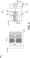
- FIG. 4 illustrates an example PRACH resource configuration 300 for panel activation at a user equipment, according to an example implementation.
- 410 of FIG. 4 illustrates a gNB (for example, BS of FIG. 1 ) transmitting a synchronization signal block (SSB), which may include a plurality of beams, to a UE (for example, UE/user device of FIG. 1 ).
- SSB synchronization signal block
- FIG. 4 illustrates the gNB transmitting SSBs/beams SSB1 (311), SSB2 (312), SSB3 (313), and SSB4 (314) to the UE.
- the UE may transmit a physical random access channel (PRACH) using PRACH resources PR1 (321), PR2 (322), PR3 (323), and PR4 (324) corresponding to SSBs/beams 311, 312, 313, and 313, respectively, as shown in FIG. 3 .
- PRACH physical random access channel
- the UE may signal the gNB of the specific panels activated at the UE by an additional uplink transmission using an additional physical resource, for example, by using an additional PRACH transmission using PRACH resources (e.g., 341, 342, etc.) configured at the UE.
- PRACH resources APR1 (341) and APR2 (342) are configured for notifying the gNB about the specific panels being activated at the UE.
- the UE may be configured with one additional PRACH resource per panel, APR1 (341) for panel 1 and APR2 (342) for panel 2.
- the UE may send PRACH via legacy or panel common PRACH resources, e.g., PRACH resources (e.g., 321, 322, 323, and 324) followed by panel specific PRACH resources (e.g., 341, 342, etc.).
- PRACH resources e.g., 321, 322, 323, and 324
- panel specific PRACH resources e.g., 341, 342, etc.
- Tx transmit
- the UE may use the same beam that is used for the recent PRACH transmission.
- the above described mechanism uses an additional transmission of PRACH but uses less resources when compared to the mechanism described above in reference to FIG. 3 .
- the above two mechanisms described above have their own advantages and provides a signaling mechanism between the UE and gNB for panel activations at the UE.
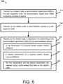
- FIG. 5 is a flow chart 500 illustrating an example panel activation mechanism 500, according to at least one example implementation, as claimed.
- a network node e.g., a gNB or BS of FIG. 1 transmits a synchronization signal block (SSB) to a user equipment (UE).
- SSB synchronization signal block
- the network node transmits an SSB 310 which may comprise a plurality of beams, e.g., 311, 312, 313, and 314.
- the network node transmits a panel activation request to the user equipment (UE).
- the panel activation request may indicate identities of the one or more panels (e.g., panel 1 and/or panel 2) to be activated at the UE or a number of panels (e.g., one or two panels) to be activated at the UE.
- the network node receives, in response to the transmitting of the synchronization signal block (SSB) and the panel activation request a first transmission of a PRACH and a second transmission of the PRACH.
- SSB synchronization signal block
- the first transmission of a PRACH uses a first PRACH resource of a first set of PRACH resources, the first set of PRACH resources configured for the plurality of the beams associated with the SSB;
- the second transmission of the PRACH uses a second PRACH resource of a second set of PRACH resources, the second transmission comprising a panel activation message and the second set of PRACH resources configured for indicating one or more panels activated at the user equipment (UE); and wherein the first transmission and the second transmission are received using a same receive (Rx) beam at the network node.
- the panel activation request may be transmitted by the network node to the UE via a physical downlink control channel (PDCCH), a radio resource control (RRC) configuration message, and/or a channel state information-reference signal (CSI-RS).
- PDCCH physical downlink control channel
- RRC radio resource control
- CSI-RS channel state information-reference signal
- FIG. 6 is a flow chart illustrating another example panel activation mechanism 600, according to at least one additional example implementation, as claimed.
- a user equipment, UE receives an SSB (e.g., SSB 410) from a network node (e.g., gNB), the synchronization signal block (SSB) comprising a plurality of beams (e.g., 411, 412, 413, and 414).
- SSB synchronization signal block
- the UE receives a panel activation request from the network node.
- the panel activation request may indicate identities of the one or more panels (e.g., panel 1 and/or panel 2) to be activated at the UE or a number of panels (e.g., one or two panels) to be activated at the UE.
- the UE measures the plurality of beams received from the network node.
- the UE may measure beams 411, 412, 413, and 414 that are received from the gNB.
- the UE activates one or more panels, e.g., panels 1 and/or 2 at the UE.
- the activation of the panels is based at least on the panel activation request received from the gNB and/or the measurements.
- the UE transmits a first transmission of a PRACH and a second transmission of the PRACH to the gNB.
- the first transmission of a PRACH uses a first PRACH resource of a first set of PRACH resources configured for the plurality of the beams associated with the SSB; a second transmission of the PRACH using a second PRACH resource of a second set of PRACH resources configured for indicating the activation of one or more panels at the UE; wherein the first transmission and the second transmission are transmitted using a same transmit (Tx) beam from the UE.
- Tx transmit
- the UE may use one or more panels for performing the measurements.
- the panel used by the UE for performing the measurements may be in a reception only state. However, if the panel to be used for measurements is in a deactivated state, the UE may transition the specific panel to the reception only state for performing the measurements.
- the panel activation request may be received from the gNB via a physical downlink control channel (PDCCH), a radio resource control (RRC) configuration message, or a CSI-RS.
- PDCCH physical downlink control channel
- RRC radio resource control
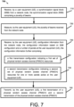
- FIG. 7 is a flow chart illustrating another example panel activation mechanism 700, according to at least one additional example implementation, as claimed.
- a user equipment, UE receives an SSB (e.g., 410) from a network node (e.g., gNB of FIG. 1 ).
- the SSB comprises a plurality of beams, e.g., 411, 412, 413, and 414.
- the UE measures the plurality of beams (e.g., 411, 412, 413, and 414) received from the network node.
- the plurality of beams e.g., 411, 412, 413, and 414.
- the UE receives configuration information from the network node.
- the configuration information received from the network node is based on SSB configuration and a number of panels at the user equipment (UE) and includes a first transmission configuration indicating a first set of PRACH resources (e.g., 321, 322, 323, and 324)configured for the plurality of beams received from the network node, and a second transmission configuration indicating a second set of PRACH resources (e.g., 341 and 342) for one or more panels active at the UE.
- a first transmission configuration indicating a first set of PRACH resources (e.g., 321, 322, 323, and 324)configured for the plurality of beams received from the network node
- a second transmission configuration indicating a second set of PRACH resources (e.g., 341 and 342) for one or more panels active at the UE.
- the UE transmits a first transmission 320 of a physical random access channel (PRACH) to the network node, the first transmission using resources (e.g., 321, 322, 323, and/or 324) based on the first transmission configuration, and a second transmission (340) of the physical random access channel (PRACH) to the network node, the second transmission using resources (341 and 342).
- PRACH physical random access channel
- the activation of panels e.g., one or more panels
- the activation of panels may be triggered by the gNB or the UE and may use any combination of the approaches as described above in detail in reference to FIGs. 2-7 .
- FIG. 8 is a block diagram 800 of a wireless station, for example, AP/gNB/eNB/MgNB/SgNB/NG-RAN node or user equipment (UE)/user device) according to an example implementation.
- the wireless station 800 may include, for example, one or more RF (radio frequency) or wireless transceivers 802A, 802B, where each wireless transceiver includes a transmitter to transmit signals and a receiver to receive signals.
- the wireless station also includes a processor or control unit/entity (controller) 804/808 to execute instructions or software and control transmission and receptions of signals, and a memory 806 to store data and/or instructions.
- Processor 804 may also make decisions or determinations, generate frames, packets or messages for transmission, decode received frames or messages for further processing, and other tasks or functions described herein.
- Processor 804 which may be a baseband processor, for example, may generate messages, packets, frames or other signals for transmission via wireless transceiver 802 (802A or 802B).
- Processor 804 may control transmission of signals or messages over a wireless network, and may control the reception of signals or messages, etc., via a wireless network (e.g., after being downconverted by wireless transceiver 802, for example).
- Processor 804 may be programmable and capable of executing software or other instructions stored in memory or on other computer media to perform the various tasks and functions described above, such as one or more of the tasks or methods described above.
- Processor 804 may be (or may include), for example, hardware, programmable logic, a programmable processor that executes software or firmware, and/or any combination of these. Using other terminology, processor 804 and transceiver 802 together may be considered as a wireless transmitter/receiver system, for example.
- a controller (or processor) 808 may execute software and instructions, and may provide overall control for the station 800, and may provide control for other systems not shown in FIG. 8 , such as controlling input/output devices (e.g., display, keypad), and/or may execute software for one or more applications that may be provided on wireless station 800, such as, for example, an email program, audio/video applications, a word processor, a Voice over IP application, or other application or software.
- a storage medium may be provided that includes stored instructions, which when executed by a controller or processor may result in the processor 804, or other controller or processor, performing one or more of the functions or tasks described above.
- RF or wireless transceiver(s) 802A/802B may receive signals or data and/or transmit or send signals or data.
- Processor 804 (and possibly transceivers 802A/802B) may control the RF or wireless transceiver 802A or 802B to receive, send, broadcast or transmit signals or data.
- 5G Another example of a suitable communications system is the 5G concept. It is assumed that network architecture in 5G will be quite similar to that of the LTE-advanced. 5G is likely to use multiple input - multiple output (MIMO) antennas, many more base stations or nodes than the LTE (a so-called small cell concept), including macro sites operating in co-operation with smaller stations and perhaps also employing a variety of radio technologies for better coverage and enhanced data rates.
- MIMO multiple input - multiple output
- NFV network functions virtualization
- a virtualized network function may comprise one or more virtual machines running computer program codes using standard or general type servers instead of customized hardware. Cloud computing or data storage may also be utilized.
- radio communications this may mean node operations may be carried out, at least partly, in a server, host or node operationally coupled to a remote radio head. It is also possible that node operations will be distributed among a plurality of servers, nodes or hosts. It should also be understood that the distribution of labor between core network operations and base station operations may differ from that of the LTE or even be non-existent.
- Implementations of the various techniques described herein may be implemented in digital electronic circuitry, or in computer hardware, firmware, software, or in combinations of them. Implementations may be implemented as a computer program product, i.e., a computer program tangibly embodied in an information carrier, e.g., in a machine-readable storage device or in a propagated signal, for execution by, or to control the operation of, a data processing apparatus, e.g., a programmable processor, a computer, or multiple computers. Implementations may also be provided on a computer readable medium or computer readable storage medium, which may be a non-transitory medium.
- Implementations of the various techniques may also include implementations provided via transitory signals or media, and/or programs and/or software implementations that are downloadable via the Internet or other network(s), either wired networks and/or wireless networks.
- implementations may be provided via machine type communications (MTC), and also via an Internet of Things (IOT).
- MTC machine type communications
- IOT Internet of Things
- the computer program may be in source code form, object code form, or in some intermediate form, and it may be stored in some sort of carrier, distribution medium, or computer readable medium, which may be any entity or device capable of carrying the program.
- carrier include a record medium, computer memory, read-only memory, photoelectrical and/or electrical carrier signal, telecommunications signal, and software distribution package, for example.
- the computer program may be executed in a single electronic digital computer or it may be distributed amongst a number of computers.
- implementations of the various techniques described herein may use a cyber-physical system (CPS) (a system of collaborating computational elements controlling physical entities).
- CPS may enable the implementation and exploitation of massive amounts of interconnected ICT devices (sensors, actuators, processors microcontrollers, etc embedded in physical objects at different locations.
- ICT devices sensors, actuators, processors microcontrollers, etc.
- Mobile cyber physical systems in which the physical system in question has inherent mobility, are a subcategory of cyber-physical systems. Examples of mobile physical systems include mobile robotics and electronics transported by humans or animals. The rise in popularity of smartphones has increased interest in the area of mobile cyber-physical systems. Therefore, various implementations of techniques described herein may be provided via one or more of these technologies.
- a computer program such as the computer program(s) described above, can be written in any form of programming language, including compiled or interpreted languages, and can be deployed in any form, including as a stand-alone program or as a module, component, subroutine, or other unit or part of it suitable for use in a computing environment.
- a computer program can be deployed to be executed on one computer or on multiple computers at one site or distributed across multiple sites and interconnected by a communication network.
- Method steps may be performed by one or more programmable processors executing a computer program or computer program portions to perform functions by operating on input data and generating output. Method steps also may be performed by, and an apparatus may be implemented as, special purpose logic circuitry, e.g., an FPGA (field programmable gate array) or an ASIC (application specific integrated circuit).
- FPGA field programmable gate array
- ASIC application specific integrated circuit
- processors suitable for the execution of a computer program include, by way of example, both general and special purpose microprocessors, and any one or more processors of any kind of digital computer, chip or chipset.
- a processor will receive instructions and data from a read only memory or a random access memory or both.
- Elements of a computer may include at least one processor for executing instructions and one or more memory devices for storing instructions and data.
- a computer also may include, or be operatively coupled to receive data from or transfer data to, or both, one or more mass storage devices for storing data, e.g., magnetic, magneto optical disks, or optical disks.
- Information carriers suitable for embodying computer program instructions and data include all forms of non volatile memory, including by way of example semiconductor memory devices, e.g., EPROM, EEPROM, and flash memory devices; magnetic disks, e.g., internal hard disks or removable disks; magneto optical disks; and CD ROM and DVD-ROM disks.
- semiconductor memory devices e.g., EPROM, EEPROM, and flash memory devices
- magnetic disks e.g., internal hard disks or removable disks
- magneto optical disks e.g., CD ROM and DVD-ROM disks.
- the processor and the memory may be supplemented by, or incorporated in, special purpose logic circuitry.
Landscapes
- Engineering & Computer Science (AREA)
- Signal Processing (AREA)
- Computer Networks & Wireless Communication (AREA)
- Quality & Reliability (AREA)
- Mobile Radio Communication Systems (AREA)
Claims (15)
- Kommunikationsverfahren, das Folgendes umfasst:Übertragen (510) eines Synchronisationssignalblocks, SSB, durch einen Netzwerkknoten zu einer Teilnehmereinrichtung, UE, wobei der Synchronisationssignalblock, SSB, eine Vielzahl von Strahlen umfasst;Übertragen (520) einer Feldaktivierungsanforderung durch den Netzwerkknoten zur Teilnehmereinrichtung, UE, undEmpfangen (530) von Folgendem durch den Netzwerkknoten in Reaktion auf das Übertragen des Synchronisationssignalblocks, SSB, und der Feldaktivierungsanforderung:einer ersten Übertragung eines physischen Direktzugriffskanals, PRACH (532), unter Verwendung einer ersten physischen Direktzugriffskanal(PRACH)-Ressource eines ersten Satzes von physischen Direktzugriffskanal(PRACH)-Ressourcen, wobei der erste Satz von physischen Direktzugriffskanal(PRACH)-Ressourcen für die Vielzahl der mit dem SSB verknüpften Strahlen ausgelegt sind,einer zweiten Übertragung des physischen Direktzugriffskanals, PRACH (534), unter Verwendung einer zweiten physischen Direktzugriffskanal(PRACH)-Ressource eines zweiten Satzes von physischen Direktzugriffskanal(PRACH)-Ressourcen, wobei die zweite Übertragung eine Feldaktivierungsnachricht umfasst und der zweite Satz von physischen Direktzugriffskanal(PRACH)-Ressourcen zum Anzeigen, dass an der Teilnehmereinrichtung, UE, ein oder mehrere Felder aktiviert wurden, ausgelegt sind, undwobei die erste Übertragung und die zweite Übertragung unter Verwendung eines selben Empfangs(Rx)-Strahls am Netzwerkknoten (536) empfangen werden.
- Verfahren nach Anspruch 1, wobei die Feldaktivierungsanforderung Folgendes anzeigt:Identitäten des einen oder der mehreren Felder, die an der Teilnehmereinrichtung, UE, zu aktivieren sind, odereine Anzahl von Feldern, die an der Teilnehmereinrichtung, UE, zu aktivieren sind.
- Verfahren nach Anspruch 2, wobei die Feldaktivierungsanforderung via einen physischen Downlinksteuerkanal, PDCCH, eine Funkressourcensteuerungs(RRC)-Auslegungsnachricht oder ein Kanalzustandsinformationsreferenzsignal, CSI-RS, übertragen wird.
- Verfahren nach Anspruch 1, wobei der Netzwerkknoten ein Funkzugangsnetzwerkknoten, ein integrierter Zugangs- und Backhaul(IAB)-Netzwerkknoten ist und/oder die Teilnehmereinrichtung, UE, ein integrierter Zugangs- und Backhaul(IAB)-Knoten ist.
- Vorrichtung, die mindestens einen Prozessor und mindestens einen Speicher umfasst, der Computeranweisungen beinhaltet, die, wenn sie von dem mindestens einen Prozessor ausgeführt werden, die Vorrichtung veranlassen, das Verfahren nach Anspruch 1 durchzuführen.
- Kommunikationsverfahren, das Folgendes umfasst:Empfangen (610) eines Synchronisationssignalblocks, SSB, durch eine Teilnehmereinrichtung, UE, von einem Netzwerkknoten, wobei der Synchronisationssignalblock, SSB, eine Vielzahl von Strahlen umfasst;Empfangen (620) einer Feldaktivierungsanforderung durch die Teilnehmereinrichtung, UE, vom Netzwerkknoten;Messen (630) der Vielzahl von Strahlen, die vom Netzwerkknoten empfangen werden, durch die Teilnehmereinrichtung, UE;Aktivieren (640) von einem oder mehreren Feldern durch die Teilnehmereinrichtung, UE, das Aktivieren basiert mindestens auf der Feldaktivierungsanforderung und/oder dem Messen; undÜbertragen (650) einer ersten Übertragung eines physischen Direktzugriffskanals, PRACH, durch die Teilnehmereinrichtung, UE, unter Verwendung einer ersten physischen Direktzugriffskanal(PRACH)-Ressource eines ersten Satzes von physischen Direktzugriffskanal(PRACH)-Ressourcen, die für die Vielzahl der mit dem SSB verknüpften Strahlen ausgelegt sind,einer zweiten Übertragung des physischen Direktzugriffskanals, PRACH, unter Verwendung einer zweiten physischen Direktzugriffskanal(PRACH)-Ressource eines zweiten Satzes von physischen Direktzugriffskanal(PRACH)-Ressourcen, die zum Anzeigen des Aktivierens von einem oder mehreren Feldern an der Teilnehmereinrichtung, UE, ausgelegt sind, undwobei die erste Übertragung und die zweite Übertragung unter Verwendung eines selben Übertragungs(Tx)-Strahls von der Teilnehmereinrichtung, UE, übertragen werden.
- Verfahren nach Anspruch 6, wobei die Feldaktivierungsanforderung Folgendes anzeigt:Identitäten des einen oder der mehreren Felder, die an der Teilnehmereinrichtung, UE, zu aktivieren sind, odereine Anzahl von Feldern, die an der Teilnehmereinrichtung, UE, zu aktivieren sind.
- Verfahren nach Anspruch 6, wobei mindestens ein Feld von der Teilnehmereinrichtung, UE, zum Durchführen des Messens verwendet wird.
- Verfahren nach Anspruch 8, wobei sich das mindestens eine Feld, das von der Teilnehmereinrichtung, UE, zum Durchführen des Messens verwendet wird, in einem Nur-Empfang-Zustand befindet.
- Verfahren nach Anspruch 8, wobei sich das mindestens eine Feld, das von der Teilnehmereinrichtung, UE, zum Durchführen des Messens verwendet wird, in einem deaktivierten Zustand befindet und zum Durchführen des Messens zum Nur-Empfang-Zustand übergeht.
- Verfahren nach Anspruch 6, wobei die Feldaktivierungsanforderung via einen physischen Downlinksteuerkanal, PDCCH, eine Funkressourcensteuerungs(RRC)-Auslegungsnachricht oder ein Kanalzustandsinformationsreferenzsignal, CSI-RS, empfangen wird.
- Verfahren nach Anspruch 6, wobei der Netzwerkknoten ein Funkzugangsnetzwerkknoten oder ein integrierter Zugangs- und Backhaul(IAB)-Netzwerkknoten ist.
- Vorrichtung, die mindestens einen Prozessor und mindestens einen Speicher umfasst, der Computeranweisungen beinhaltet, die, wenn sie von dem mindestens einen Prozessor ausgeführt werden, die Vorrichtung veranlassen, das Verfahren nach Anspruch 6 durchzuführen.
- Kommunikationsverfahren, das Folgendes umfasst:Empfangen (710) eines Synchronisationssignalblocks, SSB, durch eine Teilnehmereinrichtung, UE, von einem Netzwerkknoten, wobei der Synchronisationssignalblock, SSB, eine Vielzahl von Strahlen umfasst;Messen (720) der Vielzahl von Strahlen, die vom Netzwerkknoten empfangen werden, durch die Teilnehmereinrichtung, UE;Empfangen (730) von Auslegungsinformationen durch die Teilnehmereinrichtung, UE, vom Netzwerkknoten, die Auslegungsinformationen basieren auf einer SSB-Auslegung und einer Anzahl von Feldern an der Teilnehmereinrichtung, UE, wobei die Auslegungsinformationen ferner Folgendes umfassen:eine erste Übertragungsauslegung, die einen ersten Satz von physischen Direktzugriffskanal(PRACH)-Ressourcen (732) anzeigt, die für die Vielzahl von Strahlen ausgelegt sind, die vom Netzwerkknoten empfangen werden, undeine zweite Übertragungsauslegung, die einen zweiten Satz von physischen Direktzugriffskanal(PRACH)-Ressourcen (734) für ein oder mehrere Felder, die an der Teilnehmereinrichtung, UE, aktiv sind, anzeigt; undÜbertragen (740) von Folgendem durch die Teilnehmereinrichtung, UE:einer ersten Übertragung eines physischen Direktzugriffskanals, PRACH, zum Netzwerkknoten, wobei die erste Übertragung Ressourcen verwendet, die auf der ersten Übertragungsauslegung basieren, undeiner zweiten Übertragung des physischen Direktzugriffskanals, PRACH, zum Netzwerkknoten, wobei die zweite Übertragung Ressourcen verwendet, die auf der zweiten Übertragungsauslegung basieren.
- Vorrichtung, die mindestens einen Prozessor und mindestens einen Speicher umfasst, der Computeranweisungen beinhaltet, die, wenn sie von dem mindestens einen Prozessor ausgeführt werden, die Vorrichtung veranlassen, das Verfahren nach Anspruch 14 durchzuführen.
Applications Claiming Priority (2)
| Application Number | Priority Date | Filing Date | Title |
|---|---|---|---|
| US16/543,329 US11743830B2 (en) | 2019-08-16 | 2019-08-16 | Panel activation at a user equipment |
| PCT/EP2020/071098 WO2021032409A1 (en) | 2019-08-16 | 2020-07-27 | Panel activation at a user equipment |
Publications (2)
| Publication Number | Publication Date |
|---|---|
| EP4014664A1 EP4014664A1 (de) | 2022-06-22 |
| EP4014664B1 true EP4014664B1 (de) | 2024-09-11 |
Family
ID=71842676
Family Applications (1)
| Application Number | Title | Priority Date | Filing Date |
|---|---|---|---|
| EP20746950.3A Active EP4014664B1 (de) | 2019-08-16 | 2020-07-27 | Feldaktivierung bei einem benutzergerät |
Country Status (3)
| Country | Link |
|---|---|
| US (1) | US11743830B2 (de) |
| EP (1) | EP4014664B1 (de) |
| WO (1) | WO2021032409A1 (de) |
Families Citing this family (4)
| Publication number | Priority date | Publication date | Assignee | Title |
|---|---|---|---|---|
| JP7376598B2 (ja) * | 2019-01-14 | 2023-11-08 | ノキア テクノロジーズ オサケユイチア | 無線リソース制御非アクティブ状態におけるユーザ装置からのデータ送信 |
| US11425650B2 (en) * | 2019-04-26 | 2022-08-23 | Qualcomm Incorporated | Signaling for multi-panel UE activation |
| WO2022222137A1 (en) * | 2021-04-23 | 2022-10-27 | Qualcomm Incorporated | Configuration for user equipment cooperation |
| CN114285450B (zh) * | 2021-12-24 | 2025-06-10 | 中国电信股份有限公司 | 终端多天线面板控制方法、装置、存储介质及电子设备 |
Family Cites Families (11)
| Publication number | Priority date | Publication date | Assignee | Title |
|---|---|---|---|---|
| EP3602825A1 (de) * | 2017-03-23 | 2020-02-05 | Intel IP Corporation | Konfiguration eines prach (physikalischer direktzugriffskanal) in nr (new radio) und mehrstrahlbetrieb |
| RU2727183C1 (ru) * | 2017-05-03 | 2020-07-21 | ЭлДжи ЭЛЕКТРОНИКС ИНК. | Способ для передачи и приема канала с произвольным доступом и устройство для его передачи и приема |
| US10980064B2 (en) * | 2017-06-16 | 2021-04-13 | Futurewei Technologies, Inc. | Radio communications using random access in wireless networks |
| CN110049557B (zh) * | 2018-01-17 | 2023-06-20 | 华为技术有限公司 | 随机接入方法及装置 |
| US11026233B2 (en) * | 2018-06-20 | 2021-06-01 | Apple Inc. | Emission and panel aware beam selection |
| US11259288B2 (en) * | 2018-07-02 | 2022-02-22 | Qualcomm Incorporated | Contention-free concurrent physical random access channel transmissions |
| CN110868231B (zh) * | 2018-08-10 | 2021-08-13 | 华为技术有限公司 | 管理天线面板的方法、网络设备和终端设备 |
| WO2020063457A1 (en) * | 2018-09-27 | 2020-04-02 | Intel Corporation | Apparatus and method for user equipment panel selection |
| US11350459B2 (en) * | 2019-04-30 | 2022-05-31 | Qualcomm Incorporated | Methods and devices for facilitating random access communications in wireless communication systems |
| US11419147B2 (en) * | 2019-06-03 | 2022-08-16 | Qualcomm Incorporated | Beam association in random access procedures |
| US11729775B2 (en) * | 2019-08-15 | 2023-08-15 | Ofinno, Llc | Antenna panel activation/deactivation |
-
2019
- 2019-08-16 US US16/543,329 patent/US11743830B2/en active Active
-
2020
- 2020-07-27 EP EP20746950.3A patent/EP4014664B1/de active Active
- 2020-07-27 WO PCT/EP2020/071098 patent/WO2021032409A1/en not_active Ceased
Also Published As
| Publication number | Publication date |
|---|---|
| US11743830B2 (en) | 2023-08-29 |
| WO2021032409A1 (en) | 2021-02-25 |
| US20210051593A1 (en) | 2021-02-18 |
| EP4014664A1 (de) | 2022-06-22 |
Similar Documents
| Publication | Publication Date | Title |
|---|---|---|
| US12120774B2 (en) | Radio resource control procedures for machine learning | |
| US12413996B2 (en) | Enhanced early measurement reporting | |
| US12408062B2 (en) | Group based beam reporting | |
| EP4014664B1 (de) | Feldaktivierung bei einem benutzergerät | |
| US11985622B2 (en) | Method of correcting time of departure in observed time difference of arrival positioning | |
| EP3963927B1 (de) | Konfiguration von trägern für nicht-mobilitätsbezogene zwecke | |
| US20230283341A1 (en) | CSI Triggering and Configuration Enhancements for Partial-Reciprocity Based Port Selection Codebook | |
| US20230247672A1 (en) | Random access report in mixed network types | |
| US12609740B2 (en) | Use of transmission configuration indication state subsets for wireless communication | |
| WO2020207745A1 (en) | Integrated access and backhaul (iab) distributed unit (du) resource allocation for dual connectivity | |
| JP7668815B2 (ja) | 拡張マシンタイプ通信において14個のharqプロセスをサポートするためのharq-ack遅延 | |
| US20220400495A1 (en) | Virtual multi-transmission reception point/panel transmission for urllc | |
| US20230362753A1 (en) | Dual active protocol stack handover with coordinated pattern | |
| WO2021090239A1 (en) | Triggering of sounding reference signal transmission | |
| WO2020128750A1 (en) | Reducing uplink scheduling latency and overhead for standard packet sizes | |
| WO2021154252A1 (en) | Method for pdsch combining indication across beams | |
| US20230269022A1 (en) | Link adaptation improvement with pci reporting enhancements |
Legal Events
| Date | Code | Title | Description |
|---|---|---|---|
| STAA | Information on the status of an ep patent application or granted ep patent |
Free format text: STATUS: UNKNOWN |
|
| STAA | Information on the status of an ep patent application or granted ep patent |
Free format text: STATUS: THE INTERNATIONAL PUBLICATION HAS BEEN MADE |
|
| PUAI | Public reference made under article 153(3) epc to a published international application that has entered the european phase |
Free format text: ORIGINAL CODE: 0009012 |
|
| STAA | Information on the status of an ep patent application or granted ep patent |
Free format text: STATUS: REQUEST FOR EXAMINATION WAS MADE |
|
| 17P | Request for examination filed |
Effective date: 20220316 |
|
| AK | Designated contracting states |
Kind code of ref document: A1 Designated state(s): AL AT BE BG CH CY CZ DE DK EE ES FI FR GB GR HR HU IE IS IT LI LT LU LV MC MK MT NL NO PL PT RO RS SE SI SK SM TR |
|
| DAV | Request for validation of the european patent (deleted) | ||
| DAX | Request for extension of the european patent (deleted) | ||
| REG | Reference to a national code |
Ref country code: DE Ref legal event code: R079 Ipc: H04W0074083300 Ref country code: DE Ref legal event code: R079 Ref document number: 602020037565 Country of ref document: DE Free format text: PREVIOUS MAIN CLASS: H04W0074080000 Ipc: H04W0074083300 |
|
| GRAP | Despatch of communication of intention to grant a patent |
Free format text: ORIGINAL CODE: EPIDOSNIGR1 |
|
| STAA | Information on the status of an ep patent application or granted ep patent |
Free format text: STATUS: GRANT OF PATENT IS INTENDED |
|
| RIC1 | Information provided on ipc code assigned before grant |
Ipc: H04W 74/00 20090101ALN20240325BHEP Ipc: H04B 7/08 20060101ALI20240325BHEP Ipc: H04B 7/0404 20170101ALI20240325BHEP Ipc: H04W 74/0833 20240101AFI20240325BHEP |
|
| INTG | Intention to grant announced |
Effective date: 20240412 |
|
| RIC1 | Information provided on ipc code assigned before grant |
Ipc: H04W 74/00 20090101ALN20240404BHEP Ipc: H04B 7/08 20060101ALI20240404BHEP Ipc: H04B 7/0404 20170101ALI20240404BHEP Ipc: H04W 74/0833 20240101AFI20240404BHEP |
|
| RIN1 | Information on inventor provided before grant (corrected) |
Inventor name: VOOK, FREDERICK Inventor name: KINNUNEN, PASI EINO TAPIO Inventor name: PARK, KYOUNGMIN |
|
| GRAS | Grant fee paid |
Free format text: ORIGINAL CODE: EPIDOSNIGR3 |
|
| GRAA | (expected) grant |
Free format text: ORIGINAL CODE: 0009210 |
|
| STAA | Information on the status of an ep patent application or granted ep patent |
Free format text: STATUS: THE PATENT HAS BEEN GRANTED |
|
| AK | Designated contracting states |
Kind code of ref document: B1 Designated state(s): AL AT BE BG CH CY CZ DE DK EE ES FI FR GB GR HR HU IE IS IT LI LT LU LV MC MK MT NL NO PL PT RO RS SE SI SK SM TR |
|
| REG | Reference to a national code |
Ref country code: GB Ref legal event code: FG4D |
|
| REG | Reference to a national code |
Ref country code: CH Ref legal event code: EP |
|
| REG | Reference to a national code |
Ref country code: DE Ref legal event code: R096 Ref document number: 602020037565 Country of ref document: DE |
|
| REG | Reference to a national code |
Ref country code: IE Ref legal event code: FG4D |
|
| REG | Reference to a national code |
Ref country code: LT Ref legal event code: MG9D |
|
| PG25 | Lapsed in a contracting state [announced via postgrant information from national office to epo] |
Ref country code: NO Free format text: LAPSE BECAUSE OF FAILURE TO SUBMIT A TRANSLATION OF THE DESCRIPTION OR TO PAY THE FEE WITHIN THE PRESCRIBED TIME-LIMIT Effective date: 20241211 |
|
| REG | Reference to a national code |
Ref country code: NL Ref legal event code: MP Effective date: 20240911 |
|
| PG25 | Lapsed in a contracting state [announced via postgrant information from national office to epo] |
Ref country code: GR Free format text: LAPSE BECAUSE OF FAILURE TO SUBMIT A TRANSLATION OF THE DESCRIPTION OR TO PAY THE FEE WITHIN THE PRESCRIBED TIME-LIMIT Effective date: 20241212 Ref country code: FI Free format text: LAPSE BECAUSE OF FAILURE TO SUBMIT A TRANSLATION OF THE DESCRIPTION OR TO PAY THE FEE WITHIN THE PRESCRIBED TIME-LIMIT Effective date: 20240911 |
|
| PG25 | Lapsed in a contracting state [announced via postgrant information from national office to epo] |
Ref country code: BG Free format text: LAPSE BECAUSE OF FAILURE TO SUBMIT A TRANSLATION OF THE DESCRIPTION OR TO PAY THE FEE WITHIN THE PRESCRIBED TIME-LIMIT Effective date: 20240911 |
|
| PG25 | Lapsed in a contracting state [announced via postgrant information from national office to epo] |
Ref country code: LV Free format text: LAPSE BECAUSE OF FAILURE TO SUBMIT A TRANSLATION OF THE DESCRIPTION OR TO PAY THE FEE WITHIN THE PRESCRIBED TIME-LIMIT Effective date: 20240911 |
|
| PG25 | Lapsed in a contracting state [announced via postgrant information from national office to epo] |
Ref country code: HR Free format text: LAPSE BECAUSE OF FAILURE TO SUBMIT A TRANSLATION OF THE DESCRIPTION OR TO PAY THE FEE WITHIN THE PRESCRIBED TIME-LIMIT Effective date: 20240911 |
|
| PG25 | Lapsed in a contracting state [announced via postgrant information from national office to epo] |
Ref country code: RS Free format text: LAPSE BECAUSE OF FAILURE TO SUBMIT A TRANSLATION OF THE DESCRIPTION OR TO PAY THE FEE WITHIN THE PRESCRIBED TIME-LIMIT Effective date: 20241211 Ref country code: ES Free format text: LAPSE BECAUSE OF FAILURE TO SUBMIT A TRANSLATION OF THE DESCRIPTION OR TO PAY THE FEE WITHIN THE PRESCRIBED TIME-LIMIT Effective date: 20240911 |
|
| PG25 | Lapsed in a contracting state [announced via postgrant information from national office to epo] |
Ref country code: RS Free format text: LAPSE BECAUSE OF FAILURE TO SUBMIT A TRANSLATION OF THE DESCRIPTION OR TO PAY THE FEE WITHIN THE PRESCRIBED TIME-LIMIT Effective date: 20241211 Ref country code: NO Free format text: LAPSE BECAUSE OF FAILURE TO SUBMIT A TRANSLATION OF THE DESCRIPTION OR TO PAY THE FEE WITHIN THE PRESCRIBED TIME-LIMIT Effective date: 20241211 Ref country code: LV Free format text: LAPSE BECAUSE OF FAILURE TO SUBMIT A TRANSLATION OF THE DESCRIPTION OR TO PAY THE FEE WITHIN THE PRESCRIBED TIME-LIMIT Effective date: 20240911 Ref country code: HR Free format text: LAPSE BECAUSE OF FAILURE TO SUBMIT A TRANSLATION OF THE DESCRIPTION OR TO PAY THE FEE WITHIN THE PRESCRIBED TIME-LIMIT Effective date: 20240911 Ref country code: GR Free format text: LAPSE BECAUSE OF FAILURE TO SUBMIT A TRANSLATION OF THE DESCRIPTION OR TO PAY THE FEE WITHIN THE PRESCRIBED TIME-LIMIT Effective date: 20241212 Ref country code: FI Free format text: LAPSE BECAUSE OF FAILURE TO SUBMIT A TRANSLATION OF THE DESCRIPTION OR TO PAY THE FEE WITHIN THE PRESCRIBED TIME-LIMIT Effective date: 20240911 Ref country code: ES Free format text: LAPSE BECAUSE OF FAILURE TO SUBMIT A TRANSLATION OF THE DESCRIPTION OR TO PAY THE FEE WITHIN THE PRESCRIBED TIME-LIMIT Effective date: 20240911 Ref country code: BG Free format text: LAPSE BECAUSE OF FAILURE TO SUBMIT A TRANSLATION OF THE DESCRIPTION OR TO PAY THE FEE WITHIN THE PRESCRIBED TIME-LIMIT Effective date: 20240911 |
|
| REG | Reference to a national code |
Ref country code: AT Ref legal event code: MK05 Ref document number: 1723808 Country of ref document: AT Kind code of ref document: T Effective date: 20240911 |
|
| PG25 | Lapsed in a contracting state [announced via postgrant information from national office to epo] |
Ref country code: NL Free format text: LAPSE BECAUSE OF FAILURE TO SUBMIT A TRANSLATION OF THE DESCRIPTION OR TO PAY THE FEE WITHIN THE PRESCRIBED TIME-LIMIT Effective date: 20240911 |
|
| PG25 | Lapsed in a contracting state [announced via postgrant information from national office to epo] |
Ref country code: IS Free format text: LAPSE BECAUSE OF FAILURE TO SUBMIT A TRANSLATION OF THE DESCRIPTION OR TO PAY THE FEE WITHIN THE PRESCRIBED TIME-LIMIT Effective date: 20250111 Ref country code: PT Free format text: LAPSE BECAUSE OF FAILURE TO SUBMIT A TRANSLATION OF THE DESCRIPTION OR TO PAY THE FEE WITHIN THE PRESCRIBED TIME-LIMIT Effective date: 20250113 |
|
| PG25 | Lapsed in a contracting state [announced via postgrant information from national office to epo] |
Ref country code: RO Free format text: LAPSE BECAUSE OF FAILURE TO SUBMIT A TRANSLATION OF THE DESCRIPTION OR TO PAY THE FEE WITHIN THE PRESCRIBED TIME-LIMIT Effective date: 20240911 Ref country code: SM Free format text: LAPSE BECAUSE OF FAILURE TO SUBMIT A TRANSLATION OF THE DESCRIPTION OR TO PAY THE FEE WITHIN THE PRESCRIBED TIME-LIMIT Effective date: 20240911 |
|
| PG25 | Lapsed in a contracting state [announced via postgrant information from national office to epo] |
Ref country code: EE Free format text: LAPSE BECAUSE OF FAILURE TO SUBMIT A TRANSLATION OF THE DESCRIPTION OR TO PAY THE FEE WITHIN THE PRESCRIBED TIME-LIMIT Effective date: 20240911 Ref country code: AT Free format text: LAPSE BECAUSE OF FAILURE TO SUBMIT A TRANSLATION OF THE DESCRIPTION OR TO PAY THE FEE WITHIN THE PRESCRIBED TIME-LIMIT Effective date: 20240911 |
|
| PG25 | Lapsed in a contracting state [announced via postgrant information from national office to epo] |
Ref country code: PL Free format text: LAPSE BECAUSE OF FAILURE TO SUBMIT A TRANSLATION OF THE DESCRIPTION OR TO PAY THE FEE WITHIN THE PRESCRIBED TIME-LIMIT Effective date: 20240911 Ref country code: CZ Free format text: LAPSE BECAUSE OF FAILURE TO SUBMIT A TRANSLATION OF THE DESCRIPTION OR TO PAY THE FEE WITHIN THE PRESCRIBED TIME-LIMIT Effective date: 20240911 |
|
| PG25 | Lapsed in a contracting state [announced via postgrant information from national office to epo] |
Ref country code: SK Free format text: LAPSE BECAUSE OF FAILURE TO SUBMIT A TRANSLATION OF THE DESCRIPTION OR TO PAY THE FEE WITHIN THE PRESCRIBED TIME-LIMIT Effective date: 20240911 Ref country code: IT Free format text: LAPSE BECAUSE OF FAILURE TO SUBMIT A TRANSLATION OF THE DESCRIPTION OR TO PAY THE FEE WITHIN THE PRESCRIBED TIME-LIMIT Effective date: 20240911 |
|
| REG | Reference to a national code |
Ref country code: DE Ref legal event code: R097 Ref document number: 602020037565 Country of ref document: DE |
|
| PG25 | Lapsed in a contracting state [announced via postgrant information from national office to epo] |
Ref country code: DK Free format text: LAPSE BECAUSE OF FAILURE TO SUBMIT A TRANSLATION OF THE DESCRIPTION OR TO PAY THE FEE WITHIN THE PRESCRIBED TIME-LIMIT Effective date: 20240911 |
|
| PLBE | No opposition filed within time limit |
Free format text: ORIGINAL CODE: 0009261 |
|
| STAA | Information on the status of an ep patent application or granted ep patent |
Free format text: STATUS: NO OPPOSITION FILED WITHIN TIME LIMIT |
|
| 26N | No opposition filed |
Effective date: 20250612 |
|
| PG25 | Lapsed in a contracting state [announced via postgrant information from national office to epo] |
Ref country code: SE Free format text: LAPSE BECAUSE OF FAILURE TO SUBMIT A TRANSLATION OF THE DESCRIPTION OR TO PAY THE FEE WITHIN THE PRESCRIBED TIME-LIMIT Effective date: 20240911 |
|
| PGFP | Annual fee paid to national office [announced via postgrant information from national office to epo] |
Ref country code: DE Payment date: 20250604 Year of fee payment: 6 |
|
| REG | Reference to a national code |
Ref country code: CH Ref legal event code: H13 Free format text: ST27 STATUS EVENT CODE: U-0-0-H10-H13 (AS PROVIDED BY THE NATIONAL OFFICE) Effective date: 20260224 |
|
| PG25 | Lapsed in a contracting state [announced via postgrant information from national office to epo] |
Ref country code: LU Free format text: LAPSE BECAUSE OF NON-PAYMENT OF DUE FEES Effective date: 20250727 |
|
| GBPC | Gb: european patent ceased through non-payment of renewal fee |
Effective date: 20250727 |
|
| REG | Reference to a national code |
Ref country code: BE Ref legal event code: MM Effective date: 20250731 |
|
| PG25 | Lapsed in a contracting state [announced via postgrant information from national office to epo] |
Ref country code: GB Free format text: LAPSE BECAUSE OF NON-PAYMENT OF DUE FEES Effective date: 20250727 |
|
| PG25 | Lapsed in a contracting state [announced via postgrant information from national office to epo] |
Ref country code: BE Free format text: LAPSE BECAUSE OF NON-PAYMENT OF DUE FEES Effective date: 20250731 |
|
| PG25 | Lapsed in a contracting state [announced via postgrant information from national office to epo] |
Ref country code: FR Free format text: LAPSE BECAUSE OF NON-PAYMENT OF DUE FEES Effective date: 20250731 |
|
| PG25 | Lapsed in a contracting state [announced via postgrant information from national office to epo] |
Ref country code: CH Free format text: LAPSE BECAUSE OF NON-PAYMENT OF DUE FEES Effective date: 20250731 |