EP4014730B1 - Moulinet double roulement - Google Patents
Moulinet double roulement Download PDFInfo
- Publication number
- EP4014730B1 EP4014730B1 EP21215539.4A EP21215539A EP4014730B1 EP 4014730 B1 EP4014730 B1 EP 4014730B1 EP 21215539 A EP21215539 A EP 21215539A EP 4014730 B1 EP4014730 B1 EP 4014730B1
- Authority
- EP
- European Patent Office
- Prior art keywords
- handle
- dual
- counter
- spool
- side panels
- Prior art date
- Legal status (The legal status is an assumption and is not a legal conclusion. Google has not performed a legal analysis and makes no representation as to the accuracy of the status listed.)
- Active
Links
Images



Classifications
-
- A—HUMAN NECESSITIES
- A01—AGRICULTURE; FORESTRY; ANIMAL HUSBANDRY; HUNTING; TRAPPING; FISHING
- A01K—ANIMAL HUSBANDRY; AVICULTURE; APICULTURE; PISCICULTURE; FISHING; REARING OR BREEDING ANIMALS, NOT OTHERWISE PROVIDED FOR; NEW BREEDS OF ANIMALS
- A01K89/00—Reels
- A01K89/015—Reels with a rotary drum, i.e. with a rotating spool
-
- A—HUMAN NECESSITIES
- A01—AGRICULTURE; FORESTRY; ANIMAL HUSBANDRY; HUNTING; TRAPPING; FISHING
- A01K—ANIMAL HUSBANDRY; AVICULTURE; APICULTURE; PISCICULTURE; FISHING; REARING OR BREEDING ANIMALS, NOT OTHERWISE PROVIDED FOR; NEW BREEDS OF ANIMALS
- A01K89/00—Reels
- A01K89/015—Reels with a rotary drum, i.e. with a rotating spool
- A01K89/0192—Frame details
-
- A—HUMAN NECESSITIES
- A01—AGRICULTURE; FORESTRY; ANIMAL HUSBANDRY; HUNTING; TRAPPING; FISHING
- A01K—ANIMAL HUSBANDRY; AVICULTURE; APICULTURE; PISCICULTURE; FISHING; REARING OR BREEDING ANIMALS, NOT OTHERWISE PROVIDED FOR; NEW BREEDS OF ANIMALS
- A01K89/00—Reels
- A01K89/02—Brake devices for reels
- A01K89/033—Brake devices for reels with a rotary drum, i.e. for reels with a rotating spool
- A01K89/046—Manual pressure control
-
- A—HUMAN NECESSITIES
- A01—AGRICULTURE; FORESTRY; ANIMAL HUSBANDRY; HUNTING; TRAPPING; FISHING
- A01K—ANIMAL HUSBANDRY; AVICULTURE; APICULTURE; PISCICULTURE; FISHING; REARING OR BREEDING ANIMALS, NOT OTHERWISE PROVIDED FOR; NEW BREEDS OF ANIMALS
- A01K89/00—Reels
- A01K89/015—Reels with a rotary drum, i.e. with a rotating spool
- A01K89/01931—Spool or spool shaft details
-
- B—PERFORMING OPERATIONS; TRANSPORTING
- B65—CONVEYING; PACKING; STORING; HANDLING THIN OR FILAMENTARY MATERIAL
- B65H—HANDLING THIN OR FILAMENTARY MATERIAL, e.g. SHEETS, WEBS, CABLES
- B65H75/00—Storing webs, tapes, or filamentary material, e.g. on reels
- B65H75/02—Cores, formers, supports, or holders for coiled, wound, or folded material, e.g. reels, spindles, bobbins, cop tubes, cans, mandrels or chucks
- B65H75/34—Cores, formers, supports, or holders for coiled, wound, or folded material, e.g. reels, spindles, bobbins, cop tubes, cans, mandrels or chucks specially adapted or mounted for storing and repeatedly paying-out and re-storing lengths of material provided for particular purposes, e.g. anchored hoses, power cables
- B65H75/38—Cores, formers, supports, or holders for coiled, wound, or folded material, e.g. reels, spindles, bobbins, cop tubes, cans, mandrels or chucks specially adapted or mounted for storing and repeatedly paying-out and re-storing lengths of material provided for particular purposes, e.g. anchored hoses, power cables involving the use of a core or former internal to, and supporting, a stored package of material
- B65H75/44—Constructional details
- B65H75/4418—Arrangements for stopping winding or unwinding; Arrangements for releasing the stop means
- B65H75/4428—Arrangements for stopping winding or unwinding; Arrangements for releasing the stop means acting on the reel or on a reel blocking mechanism
-
- B—PERFORMING OPERATIONS; TRANSPORTING
- B65—CONVEYING; PACKING; STORING; HANDLING THIN OR FILAMENTARY MATERIAL
- B65H—HANDLING THIN OR FILAMENTARY MATERIAL, e.g. SHEETS, WEBS, CABLES
- B65H2701/00—Handled material; Storage means
- B65H2701/30—Handled filamentary material
- B65H2701/35—Ropes, lines
- B65H2701/355—Fishlines
Definitions
- the present invention relates to a dual-bearing reel and, more particularly, to a dual-bearing reel that provides a better hold for a thumb of a hand holding a counter handle-side side panel of a reel body during winding or jerking.
- dual-bearing reels each having, between a left and a right side panel of a reel body, a rotatably supported spool that a fishline is wound on
- dual-bearing reels for use in jerking jigging which is a strict manipulation involving winding using a handle during jerking, and others.
- a dual-bearing reel disclosed in Patent Literature 1 has a left and a right side panel that are round in shape and enables easier thumbing when jerking is performed with the counter handle-side side panel gripped.
- This dual-bearing reel has an improvement in relative position of a chamfer of an outer peripheral end of the counter handle-side side panel and an outer peripheral edge surface of a flange of a spool, thus enabling easy shifting from the chamfer to the outer peripheral edge surface.
- smooth thumbing with no sense of discomfort is therefore enabled with a hold on the counter handle-side side panel being sustained.
- Patent Literature 1 allows a thumb of a holding hand to smoothly shift toward a fishline on the spool.
- jerking during fishing requires that a pad of the thumb of that holding hand give a hard press to an outer periphery of the counter handle-side side panel with a grip end of a fishing rod securely abutted against a forearm for keeping a reel body immobile.
- the side panel described in Literature 1 is of mere shape to include, on an inner side of its upper surface portion, the chamfer having the same inclination as the flange of the spool for facilitating the shifting from the upper surface portion to the flange of the spool.
- outer surface portions other than the chamfer are substantially flat. For this reason, when jerking or the like is performed with the thumb pressing the upper surface portion of the side panel, the pad of the thumb easily slides outward from the outer periphery of the side panel, problematically resulting in no secure hold.
- the present invention has been made in view of the above problem, and an object of the present invention is to provide a dual-bearing reel that provides a better hold on a counter handle-side side panel even during strict jerking such as jigging.
- a dual-bearing reel according to the present invention as defined in claim 1 enables a rotatably supported spool between a left and a right side panel of a reel body to be rotated with a handle provided at one of the side panels and includes a movement restraining portion that is provided on an outer peripheral surface of a counter handle-side one of the side panels of the reel body, and that prevents a pressing thumb of a hand from moving outward from the counter handle-side one of the side panels.
- the present invention is defined by claim 1 appended hereto.
- the dual-bearing reel according to the present invention provides the better hold on the counter handle-side side panel even during strict jerking such as jigging.
- a dual-bearing reel 1 is configured to be most suitable for jigging, and its reel body 2 includes a left side panel 2A, a right side panel 2B, and a spool 3 rotatably supported between the side panels 2A and 2B.
- a handle 5 is provided at the right side panel 2B. Operating the handle 5 for winding rotates the spool 3 via a publicly known power transmission mechanism disposed in the right side panel 2B.
- the reel body 2 includes a frame 7 that includes the left and right side panels 2A and 2B.
- the frame 7 is formed as a single body made of, for example, a metal material such as an aluminum alloy and includes a left frame body 7A that is substantially circular in side view and a right frame body 7B that is substantially circular in side view.
- the left frame body 7A serves as the left side panel (counter handle-side side panel) 2A
- the right frame body 7B forms the right side panel 2B with a cover 8 fitted on the right frame body 7B.
- the counter handle-side side panel 2A (left frame body 7A) is formed smaller than the handle-side side panel 2B, which houses the power transmission mechanism, thus improving hold sustainably and making the reel body 2 smaller.
- the frame 7 structurally includes connecting parts connecting the left side panel 2A (left frame body 7A) and the right frame body 7B.
- a front connecting part 7C is provided in front of the spool 3
- a rear connecting part 7D is provided behind the spool 3
- two lower connecting parts 7E are provided below and adjacent to the spool 3.
- These connecting parts are formed integrally with the left side panel 2A and the right frame body 7B.
- the lower connecting parts 7E are fitted with a reel leg 7F (which may be formed integrally with the frame 7) that is to be fitted to a reel seat of a fishing rod R.
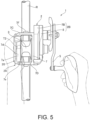
- the left side panel 2A of the frame 7 is formed substantially circular in side view as described above and is a solid structure having a reduced thickness. As FIGS. 1 and 5 illustrate, the left side panel 2A is configured to enable the reel body 2 to be held together with the fishing rod R when an outer peripheral surface (circumferential surface) 7a is pressed from above by a pad of a thumb T2 of a left hand with an index finger T1 of the left hand hooked around the fishing rod R.
- the left hand does not abut against an outer face of the left side panel 2A at its entire palm (the reel body 2 is not held with the palm).
- the pressing thumb T2 easily slips, there will be a deteriorated hold on the reel body 2. Therefore, a movement restraining portion 20 is provided to prevent the thumb T2 pressing the outer peripheral surface 7a of the left side panel 2A from moving outward from the left side panel 2A, thus enabling a stable hold.
- a description is hereinafter provided of structure of the movement restraining portion 20 according to the present embodiment.
- the dual-bearing reel 1 has an opening (free of a connecting part such as a thumb rest) above the spool 3, which is rotatably supported between the left and right side panels 2A and 2B.
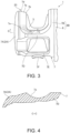
- the movement restraining portion 20 is formed directly on the outer peripheral surface 7a of the counter handle-side (left) side panel 2A. Therefore, according to the structure of the reel body 2 according to the present embodiment, when the frame 7 is formed, the integral movement restraining portion 20 can be formed integrally by machining an upper portion of the outer peripheral surface 7a of the left side panel 2A into a predetermined shape described below.
- the movement restraining portion 20 may be of any structure that prevents a thumb pressing the outer peripheral surface 7a of the left side panel 2A from above from slipping outward and is provided as an inclined portion 7d in the present embodiment.
- the frame 7 is formed to increase in dimension radially outward from its spool-side outer peripheral edge 7b, which defines the opening above the spool 3, toward its counter spool-side outer peripheral edge, thus forming the inclined portion 7d.
- This inclined portion 7d is easy to form during the frame formation, and during fishing, the inclination makes it difficult for the pressing thumb T2 to move axially outward while not causing the thumb T2 to feel a sense of discomfort with the press. Even when winding is performed using the handle 5 while strenuous jigging, a stably sustained hold is obtained.
- the inclined portion 7d which serves as the movement restraining portion 20, is formed directly on the outer peripheral surface 7a of the left side panel 2A
- the inclined portion 7d may be formed to extend along the whole periphery of the outer peripheral surface 7a; however, the inclined portion 7d should be formed at least in an area that a pad of a holding thumb presses.
- the inclined portion 7d is formed within an axial width A of the left side panel 2A (that is great enough to allow the pad of the thumb T2 to touch when the thumb T2 presses the left side panel 2A from above) and is formed to rise from the outer peripheral edge 7b.
- an anti-slip property (a sustained hold using a thumb during jerking) and reeling maneuverability (which encompasses holdability, an operational feeling, ease of gripping when the reel body 2 is held together with a fishing rod, size, weight perception, and others) need to be considered.
- Too small or too large an axial width A of the left side panel 2A will deteriorate holdability and maneuverability. If the axial width A is too large, there will also be an increase in weight. No consideration to a ratio (B/A) of the width B of the inclined portion 7d to the width A will deteriorate holdability, maneuverability, and result in a sense of discomfort. Moreover, if the inclined portion 7d forms too large an angle (inclination angle ⁇ rising with respect to an axial direction X parallel to a spool shaft), the side panel 2A itself will have a larger diameter and abut hard against a pad of a thumb, thus resulting in deteriorated holdability and maneuverability. Too small an inclination angle ⁇ , on the other hand, will result in insufficient anti-slip effect.
- the plurality of sample reels prepared for the sensory tests had the counter handle-side side panels 2A that were circular and smaller in diameter as in the drawings.
- Five panelists evaluated grip performances (the anti-slip property and the reeling maneuverability) of each of the sample reels when holding the counter handle-side side panel 2A together with a grip end of the fishing rod R in one hand as in FIG. 1 .
- the plurality of prepared sample reels had varying FIG. 2 ratios B/A (varying width proportions of the inclined portion 7d formed on the outer peripheral surfaces 7a of their counter handle-side (left) side panels 2A) and varying inclination angles ⁇ .
- Other conditions of the sample reel preparation such as the whole width A of the counter handle-side side panel 2A, the spool 3, a frame body, the handle-side side panel 2B, and the drive mechanism, were the same.
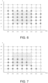
- FIG. 6 is the table showing results of the evaluation of the anti-slip property (the sustained hold using a thumb during jerking).
- FIG. 7 is the table showing results of the evaluation of the reeling maneuverability (which includes the holdability and the operational feeling) when the handle 5 was operated for winding with the reel body 2 held.
- slippages were observed when the inclination angle ⁇ was as small as 5° (see FIG. 6 ), while there were improved anti-slip effects (see FIG. 6 ) and generally satisfactory reeling maneuverabilities (see FIG. 7 ) when the inclination angle ⁇ was set to 10°.
- the upper limit for the inclination angle ⁇ it is considered that larger inclination angle ⁇ results in an enhanced anti-slip effect, but too large inclination angle ⁇ will result in a stronger sense of discomfort in a holding thumb during jerking. According to the evaluation results in FIG. 6 , setting the upper limit to 35° or less is preferable. However, given the reeling maneuverabilities (see FIG. 7 ), it is conceivable that the upper limit is preferably set in a range of 25° to 30°, and more preferably to 20° or less.
- the inclination angle ⁇ is preferably formed to be within a range of 10° to 30° and more preferably of 10° to 20° in order to make it difficult for a pad of a thumb to slip outward.
- the proportion (B/A) of the inclined portion 7d to the whole width A is related to the above-described inclination angle ⁇ .
- the proportion (B/A) is preferably 30% or more and more preferably 40% or more.
- An upper limit of 90% for the proportion (B/A) is problematic in terms of size and weight perception when the inclination angle ⁇ is equal to or larger than 25° (see FIG. 7 ). Therefore, the upper limit for the proportion (B/A) is preferably set to 80% or less.
- the obtained result indicates that the inclined portion 7d is preferably formed such that the proportion (B/A) of the inclined portion 7d to the whole width A is in a range of 30% to 80%, and more preferably formed such that the proportion (B/A) is in a range of 40% to 80%. If jigging is to be performed, a dual-bearing reel configured to have the inclination angle ⁇ in the range of 10° to 20° and the proportion (B/A) in the range of 40% to 70% in particular will conceivably be more preferable with respect to both the anti-slip property and the reeling maneuverability.
- the present invention makes it difficult for a thumb that holds the counter handle-side side panel 2A to be displaced. Therefore, when the reel body 2 is to be a frame structure integrally formed of, for example, a metal material such as an aluminum alloy, it is preferable to integrally form a structure that enhances the function of the movement restraining portion 20 on the left side panel side of the rear connecting part 7D behind the spool 3.
- a recess 7e that is formed continuously with the movement restraining portion 20 (inclined portion 7d) on the left side panel side of the rear connecting part 7D allows a palm side of a base of a thumb that holds as in FIG. 5 to fit in and more advantageously abut, thus enabling a more sustained hold.
- a recess 7e continuously with an upper face to extend to a rear face of the rear connecting part 7D, a more stable hold without causing a sense of discomfort in the base of the thumb is achieved.
- the movement restraining portion 20 is the inclined portion 7d that linearly rises axially outward.
- any appropriately modified movement restraining portion is possible as long as a movement restraining portion is provided on an outer peripheral surface of a side panel where a thumb of a hand holding also a fishing rod presses, prevents the thumb from moving outward during jerking or when winding using a handle is performed during jerking, and provides good reeling maneuverability.
- a resulting dual-bearing reel provides further improved anti-slip property and further improved reeling maneuverability.
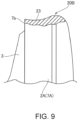
- FIG. 9 illustrates a movement restraining portion according to a second variation provided on the outer peripheral surface 7a of the counter handle-side side panel 2A.
- the movement restraining portion 20B according to the present variation is configured by forming a recess 23 in the outer peripheral surface 7a of the side panel where a thumb presses.
- a recess 23 is preferably of a shape that curves along a pad of a pressing thumb. This enables the thumb to advantageously fit in, and a resulting dual-bearing reel will provide a good anti-slip property and good reeling maneuverability.
- the irregularities 22 illustrated in FIG. 8 may also be formed.
- the above-described embodiment according to the present invention is not restrictive of the present invention, and various modifications may be made in the present invention.
- the handle 5 may be installed at the left side panel 2A.
- the frame 7 may be of any structure.
- the counter handle-side side panel 2A may have a cover as with the right side panel 2B.
- the side panels 2A and 2B may be appropriately changed in shape.
- the side panels 2A and 2B may be noncircular.
- each of the movement restraining portions 20, 20A, and 20B may be formed, for example, on a member that is separate from the frame 7 and is fixed to the outer peripheral surface 7a of the side panel 2A as long as each of the movement restraining portions 20, 20A, and 20B is provided above the outer peripheral surface 7a of the side panel 2A and within the width A of the side panel 2A.
- the member may be a thumb rest, a control case including a display unit that displays how much of a fishline has been drawn, or the like.
Landscapes
- Life Sciences & Earth Sciences (AREA)
- Environmental Sciences (AREA)
- Animal Husbandry (AREA)
- Biodiversity & Conservation Biology (AREA)
- Electric Vacuum Cleaner (AREA)
- Storing, Repeated Paying-Out, And Re-Storing Of Elongated Articles (AREA)
- Storage Of Web-Like Or Filamentary Materials (AREA)
Claims (6)
- Moulinet à double palier (1) comprenant un corps de moulinet (2), une poignée (5), et un enrouleur supporté de manière rotative (3), qui permet audit enrouleur supporté de manière rotative (3) entre un panneau latéral gauche (2A) et un panneau latéral droit (2B) du corps de moulinet (2) d'être mis en rotation avec la poignée (5) disposée sur l'un des panneaux latéraux gauche et droit (2A, 2B),
le moulinet à double palier (1) comprenant :une partie de restriction de mouvement (20) qui est disposée sur une surface périphérique extérieure (7a) d'un panneau côté opposé à la poignée des panneaux latéraux gauche et droit du corps de moulinet (2), et qui empêche un pouce pressant d'une main de se déplacer vers l'extérieur du panneau côté opposé à la poignée des panneaux latéraux gauche et droit (2A, 2B),dans lequel le corps de moulinet (2) comporte un cadre (7) qui comporte les panneaux latéraux gauche et droit (2A, 2B), sous la forme d'un corps de cadre gauche (7A) qui est sensiblement circulaire sur une vue de côté et d'un corps de cadre droit (7B) qui est sensiblement circulaire sur une vue de côté, le cadre (7) comportant structurellement des parties de connexion connectant le corps de cadre gauche (7A) et le corps de cadre droit (7B), les parties de connexion comprenant une partie de connexion arrière (7D) disposée derrière l'enrouleur (3) et formée d'un seul tenant avec le panneau côté opposé à la poignée des panneaux latéraux gauche et droit (2A, 2B) et le panneau côté poignée formant les corps de cadre gauche et droit (7A, 7B), caractérisé en ce qu'un évidement (7e) est formé en continu avec la partie de restriction de mouvement (20) sur le panneau côté opposé à la poignée des panneaux latéraux gauche et droit (2A, 2B) d'une partie de connexion arrière (7D) derrière l'enrouleur (3), l'évidement (7e) étant configuré pour permettre à un côté paume d'une base d'un pouce qui tient le panneau côté opposé à la poignée des panneaux latéraux gauche et droit (2A, 2B) de s'ajuster à celui-ci. - Moulinet à double palier (1) selon la revendication 1, dans lequel la partie de restriction de mouvement (20) est disposée sur la surface périphérique extérieure (7a) du panneau côté opposé à la poignée des panneaux latéraux gauche et droit (2A, 2B) à proximité d'une ouverture au-dessus de l'enrouleur.
- Moulinet à double palier (1) selon la revendication 1, dans lequel la partie de restriction de mouvement (20) est une partie inclinée dont la dimension augmente radialement vers l'extérieur à partir d'un bord périphérique extérieur côté enrouleur du panneau côté opposé à la poignée des panneaux latéraux gauche et droit vers un bord périphérique extérieur côté opposé à l'enrouleur du panneau côté opposé à la poignée des panneaux latéraux gauche et droit (2A, 2B).
- Moulinet à double palier (1) selon l'une quelconque des revendications 1 à 3, dans lequel la partie de restriction de mouvement (20) est formée d'un seul tenant avec le panneau côté opposé à la poignée des panneaux latéraux gauche et droit (2A, 2B).
- Moulinet à double palier (1) selon l'une quelconque des revendications 1 à 4, dans lequel le panneau côté opposé à la poignée des panneaux latéraux gauche et droit (2A, 2B) est formé avec un diamètre extérieur plus petit qu'un panneau côté poignée des panneaux latéraux gauche et droit (2A, 2B).
- Moulinet à double palier (1) selon l'une quelconque des revendications 3 à 5, dans lequel la partie de restriction de mouvement (20) est formée sur une partie du panneau côté opposé à la poignée des panneaux latéraux gauche et droit (2A, 2B), la partie s'étendant sur 30 % à 80 % de la largeur totale du panneau côté opposé à la poignée, et est formée pour établir un angle de 10° à 30° avec une ligne de référence parallèle à un axe d'un arbre d'enrouleur.
Applications Claiming Priority (1)
| Application Number | Priority Date | Filing Date | Title |
|---|---|---|---|
| JP2020211349A JP7436354B2 (ja) | 2020-12-21 | 2020-12-21 | 両軸受けリール |
Publications (2)
| Publication Number | Publication Date |
|---|---|
| EP4014730A1 EP4014730A1 (fr) | 2022-06-22 |
| EP4014730B1 true EP4014730B1 (fr) | 2025-03-19 |
Family
ID=78957222
Family Applications (1)
| Application Number | Title | Priority Date | Filing Date |
|---|---|---|---|
| EP21215539.4A Active EP4014730B1 (fr) | 2020-12-21 | 2021-12-17 | Moulinet double roulement |
Country Status (7)
| Country | Link |
|---|---|
| US (1) | US11785929B2 (fr) |
| EP (1) | EP4014730B1 (fr) |
| JP (1) | JP7436354B2 (fr) |
| KR (1) | KR20220089655A (fr) |
| CN (1) | CN114642194A (fr) |
| AU (1) | AU2021277696B2 (fr) |
| TW (1) | TWI790816B (fr) |
Families Citing this family (2)
| Publication number | Priority date | Publication date | Assignee | Title |
|---|---|---|---|---|
| JP7843776B2 (ja) | 2021-11-24 | 2026-04-10 | 住友重機械工業株式会社 | リール装置 |
| JP1719924S (ja) * | 2021-12-22 | 2022-07-15 | 釣用リール |
Citations (1)
| Publication number | Priority date | Publication date | Assignee | Title |
|---|---|---|---|---|
| US4821978A (en) * | 1986-01-31 | 1989-04-18 | Daiwa Seiko, Inc. | Twin-bearing type fishing reel |
Family Cites Families (13)
| Publication number | Priority date | Publication date | Assignee | Title |
|---|---|---|---|---|
| JP2536093Y2 (ja) * | 1990-04-18 | 1997-05-21 | ダイワ精工株式会社 | 魚釣用リール |
| JP3797765B2 (ja) * | 1997-10-09 | 2006-07-19 | 株式会社シマノ | 両軸受リール |
| US5988548A (en) * | 1998-05-14 | 1999-11-23 | Johnson Worldwide Associates | Easy hold fishing reel body |
| JP2000324984A (ja) * | 1999-05-24 | 2000-11-28 | Daiwa Seiko Inc | 魚釣用リール |
| TWI331013B (en) * | 2004-06-25 | 2010-10-01 | Shimano Kk | Spool assembly for a dual bearing reel |
| JP2010063435A (ja) * | 2008-09-12 | 2010-03-25 | Globeride Inc | 魚釣用リール |
| KR101785730B1 (ko) * | 2010-06-28 | 2017-10-16 | 글로브라이드 가부시키가이샤 | 낚시용 전동 릴 |
| KR101699382B1 (ko) * | 2014-10-22 | 2017-01-24 | 유한책임회사 도요엔지니어링 | 가공성이 향상된 낚시릴 프레임 |
| JP2016178886A (ja) * | 2015-03-24 | 2016-10-13 | グローブライド株式会社 | 両軸受型リール |
| JP6804831B2 (ja) * | 2015-07-14 | 2020-12-23 | グローブライド株式会社 | 両軸受型リール |
| US10271531B2 (en) * | 2016-04-26 | 2019-04-30 | Doyo Engineering Co., Ltd. | Fishing reel equipped with replaceable hood top |
| JP6846156B2 (ja) * | 2016-10-19 | 2021-03-24 | 株式会社シマノ | 両軸受リール |
| JP7186633B2 (ja) * | 2019-02-13 | 2022-12-09 | 株式会社シマノ | 両軸受リール |
-
2020
- 2020-12-21 JP JP2020211349A patent/JP7436354B2/ja active Active
-
2021
- 2021-11-15 TW TW110142362A patent/TWI790816B/zh active
- 2021-11-15 CN CN202111347773.3A patent/CN114642194A/zh active Pending
- 2021-12-01 AU AU2021277696A patent/AU2021277696B2/en active Active
- 2021-12-01 US US17/539,466 patent/US11785929B2/en active Active
- 2021-12-16 KR KR1020210180421A patent/KR20220089655A/ko active Pending
- 2021-12-17 EP EP21215539.4A patent/EP4014730B1/fr active Active
Patent Citations (1)
| Publication number | Priority date | Publication date | Assignee | Title |
|---|---|---|---|---|
| US4821978A (en) * | 1986-01-31 | 1989-04-18 | Daiwa Seiko, Inc. | Twin-bearing type fishing reel |
Also Published As
| Publication number | Publication date |
|---|---|
| AU2021277696B2 (en) | 2023-10-05 |
| US11785929B2 (en) | 2023-10-17 |
| TWI790816B (zh) | 2023-01-21 |
| EP4014730A1 (fr) | 2022-06-22 |
| US20220192170A1 (en) | 2022-06-23 |
| KR20220089655A (ko) | 2022-06-28 |
| JP2022098036A (ja) | 2022-07-01 |
| JP7436354B2 (ja) | 2024-02-21 |
| TW202224556A (zh) | 2022-07-01 |
| CN114642194A (zh) | 2022-06-21 |
| AU2021277696A1 (en) | 2022-07-07 |
Similar Documents
| Publication | Publication Date | Title |
|---|---|---|
| CA2315442C (fr) | Poignee de canne a peche | |
| AU2021277696B2 (en) | Dual-bearing reel | |
| US5183221A (en) | Fishing reel | |
| KR101785730B1 (ko) | 낚시용 전동 릴 | |
| WO2022044787A1 (fr) | Porte-moulinet | |
| US9807990B2 (en) | Double bearing reel | |
| JP5698066B2 (ja) | 魚釣用電動リール | |
| JP2597385Y2 (ja) | リールシート | |
| JP4954339B2 (ja) | 魚釣用電動リール | |
| US6988684B2 (en) | Handle assembly for fishing reel | |
| JP2022094476A (ja) | 釣竿用のリールシート | |
| US9693543B2 (en) | Double bearing reel | |
| JP2016178886A (ja) | 両軸受型リール | |
| JP5118536B2 (ja) | 釣竿 | |
| JP4225927B2 (ja) | 釣竿 | |
| HK40069302A (en) | Dual-bearing reel | |
| JPH11253078A (ja) | 両軸受リール | |
| JP2003009735A (ja) | 釣り用リールのハンドル組立体 | |
| JP2007295805A (ja) | 釣竿 | |
| JP3182448U (ja) | 魚釣り用リールのハンドル | |
| JP2007202453A (ja) | 魚釣用リール | |
| WO2024189983A1 (fr) | Moulinet de pêche | |
| JP2002238414A (ja) | 魚釣用両軸受リール | |
| JP3892709B2 (ja) | 釣竿 | |
| JP2010081883A (ja) | 魚釣用リール |
Legal Events
| Date | Code | Title | Description |
|---|---|---|---|
| PUAI | Public reference made under article 153(3) epc to a published international application that has entered the european phase |
Free format text: ORIGINAL CODE: 0009012 |
|
| STAA | Information on the status of an ep patent application or granted ep patent |
Free format text: STATUS: REQUEST FOR EXAMINATION WAS MADE |
|
| 17P | Request for examination filed |
Effective date: 20211217 |
|
| AK | Designated contracting states |
Kind code of ref document: A1 Designated state(s): AL AT BE BG CH CY CZ DE DK EE ES FI FR GB GR HR HU IE IS IT LI LT LU LV MC MK MT NL NO PL PT RO RS SE SI SK SM TR |
|
| STAA | Information on the status of an ep patent application or granted ep patent |
Free format text: STATUS: EXAMINATION IS IN PROGRESS |
|
| P01 | Opt-out of the competence of the unified patent court (upc) registered |
Effective date: 20230511 |
|
| 17Q | First examination report despatched |
Effective date: 20230612 |
|
| GRAP | Despatch of communication of intention to grant a patent |
Free format text: ORIGINAL CODE: EPIDOSNIGR1 |
|
| STAA | Information on the status of an ep patent application or granted ep patent |
Free format text: STATUS: GRANT OF PATENT IS INTENDED |
|
| INTG | Intention to grant announced |
Effective date: 20241111 |
|
| GRAS | Grant fee paid |
Free format text: ORIGINAL CODE: EPIDOSNIGR3 |
|
| GRAA | (expected) grant |
Free format text: ORIGINAL CODE: 0009210 |
|
| STAA | Information on the status of an ep patent application or granted ep patent |
Free format text: STATUS: THE PATENT HAS BEEN GRANTED |
|
| AK | Designated contracting states |
Kind code of ref document: B1 Designated state(s): AL AT BE BG CH CY CZ DE DK EE ES FI FR GB GR HR HU IE IS IT LI LT LU LV MC MK MT NL NO PL PT RO RS SE SI SK SM TR |
|
| REG | Reference to a national code |
Ref country code: GB Ref legal event code: FG4D |
|
| REG | Reference to a national code |
Ref country code: CH Ref legal event code: EP |
|
| REG | Reference to a national code |
Ref country code: IE Ref legal event code: FG4D |
|
| REG | Reference to a national code |
Ref country code: DE Ref legal event code: R096 Ref document number: 602021027764 Country of ref document: DE |
|
| PG25 | Lapsed in a contracting state [announced via postgrant information from national office to epo] |
Ref country code: RS Free format text: LAPSE BECAUSE OF FAILURE TO SUBMIT A TRANSLATION OF THE DESCRIPTION OR TO PAY THE FEE WITHIN THE PRESCRIBED TIME-LIMIT Effective date: 20250619 |
|
| PG25 | Lapsed in a contracting state [announced via postgrant information from national office to epo] |
Ref country code: FI Free format text: LAPSE BECAUSE OF FAILURE TO SUBMIT A TRANSLATION OF THE DESCRIPTION OR TO PAY THE FEE WITHIN THE PRESCRIBED TIME-LIMIT Effective date: 20250319 |
|
| REG | Reference to a national code |
Ref country code: LT Ref legal event code: MG9D |
|
| PG25 | Lapsed in a contracting state [announced via postgrant information from national office to epo] |
Ref country code: NO Free format text: LAPSE BECAUSE OF FAILURE TO SUBMIT A TRANSLATION OF THE DESCRIPTION OR TO PAY THE FEE WITHIN THE PRESCRIBED TIME-LIMIT Effective date: 20250619 |
|
| PG25 | Lapsed in a contracting state [announced via postgrant information from national office to epo] |
Ref country code: HR Free format text: LAPSE BECAUSE OF FAILURE TO SUBMIT A TRANSLATION OF THE DESCRIPTION OR TO PAY THE FEE WITHIN THE PRESCRIBED TIME-LIMIT Effective date: 20250319 |
|
| PG25 | Lapsed in a contracting state [announced via postgrant information from national office to epo] |
Ref country code: LV Free format text: LAPSE BECAUSE OF FAILURE TO SUBMIT A TRANSLATION OF THE DESCRIPTION OR TO PAY THE FEE WITHIN THE PRESCRIBED TIME-LIMIT Effective date: 20250319 |
|
| PG25 | Lapsed in a contracting state [announced via postgrant information from national office to epo] |
Ref country code: GR Free format text: LAPSE BECAUSE OF FAILURE TO SUBMIT A TRANSLATION OF THE DESCRIPTION OR TO PAY THE FEE WITHIN THE PRESCRIBED TIME-LIMIT Effective date: 20250620 Ref country code: BG Free format text: LAPSE BECAUSE OF FAILURE TO SUBMIT A TRANSLATION OF THE DESCRIPTION OR TO PAY THE FEE WITHIN THE PRESCRIBED TIME-LIMIT Effective date: 20250319 |
|
| REG | Reference to a national code |
Ref country code: NL Ref legal event code: MP Effective date: 20250319 |
|
| REG | Reference to a national code |
Ref country code: AT Ref legal event code: MK05 Ref document number: 1776141 Country of ref document: AT Kind code of ref document: T Effective date: 20250319 |
|
| PG25 | Lapsed in a contracting state [announced via postgrant information from national office to epo] |
Ref country code: NL Free format text: LAPSE BECAUSE OF FAILURE TO SUBMIT A TRANSLATION OF THE DESCRIPTION OR TO PAY THE FEE WITHIN THE PRESCRIBED TIME-LIMIT Effective date: 20250319 |
|
| PG25 | Lapsed in a contracting state [announced via postgrant information from national office to epo] |
Ref country code: SE Free format text: LAPSE BECAUSE OF FAILURE TO SUBMIT A TRANSLATION OF THE DESCRIPTION OR TO PAY THE FEE WITHIN THE PRESCRIBED TIME-LIMIT Effective date: 20250319 |
|
| PG25 | Lapsed in a contracting state [announced via postgrant information from national office to epo] |
Ref country code: SM Free format text: LAPSE BECAUSE OF FAILURE TO SUBMIT A TRANSLATION OF THE DESCRIPTION OR TO PAY THE FEE WITHIN THE PRESCRIBED TIME-LIMIT Effective date: 20250319 |
|
| PG25 | Lapsed in a contracting state [announced via postgrant information from national office to epo] |
Ref country code: ES Free format text: LAPSE BECAUSE OF FAILURE TO SUBMIT A TRANSLATION OF THE DESCRIPTION OR TO PAY THE FEE WITHIN THE PRESCRIBED TIME-LIMIT Effective date: 20250319 Ref country code: PT Free format text: LAPSE BECAUSE OF FAILURE TO SUBMIT A TRANSLATION OF THE DESCRIPTION OR TO PAY THE FEE WITHIN THE PRESCRIBED TIME-LIMIT Effective date: 20250721 |
|
| PG25 | Lapsed in a contracting state [announced via postgrant information from national office to epo] |
Ref country code: PL Free format text: LAPSE BECAUSE OF FAILURE TO SUBMIT A TRANSLATION OF THE DESCRIPTION OR TO PAY THE FEE WITHIN THE PRESCRIBED TIME-LIMIT Effective date: 20250319 Ref country code: IT Free format text: LAPSE BECAUSE OF FAILURE TO SUBMIT A TRANSLATION OF THE DESCRIPTION OR TO PAY THE FEE WITHIN THE PRESCRIBED TIME-LIMIT Effective date: 20250319 |
|
| PG25 | Lapsed in a contracting state [announced via postgrant information from national office to epo] |
Ref country code: AT Free format text: LAPSE BECAUSE OF FAILURE TO SUBMIT A TRANSLATION OF THE DESCRIPTION OR TO PAY THE FEE WITHIN THE PRESCRIBED TIME-LIMIT Effective date: 20250319 |
|
| PG25 | Lapsed in a contracting state [announced via postgrant information from national office to epo] |
Ref country code: CZ Free format text: LAPSE BECAUSE OF FAILURE TO SUBMIT A TRANSLATION OF THE DESCRIPTION OR TO PAY THE FEE WITHIN THE PRESCRIBED TIME-LIMIT Effective date: 20250319 Ref country code: EE Free format text: LAPSE BECAUSE OF FAILURE TO SUBMIT A TRANSLATION OF THE DESCRIPTION OR TO PAY THE FEE WITHIN THE PRESCRIBED TIME-LIMIT Effective date: 20250319 |
|
| PG25 | Lapsed in a contracting state [announced via postgrant information from national office to epo] |
Ref country code: RO Free format text: LAPSE BECAUSE OF FAILURE TO SUBMIT A TRANSLATION OF THE DESCRIPTION OR TO PAY THE FEE WITHIN THE PRESCRIBED TIME-LIMIT Effective date: 20250319 |
|
| PG25 | Lapsed in a contracting state [announced via postgrant information from national office to epo] |
Ref country code: SK Free format text: LAPSE BECAUSE OF FAILURE TO SUBMIT A TRANSLATION OF THE DESCRIPTION OR TO PAY THE FEE WITHIN THE PRESCRIBED TIME-LIMIT Effective date: 20250319 |
|
| PG25 | Lapsed in a contracting state [announced via postgrant information from national office to epo] |
Ref country code: IS Free format text: LAPSE BECAUSE OF FAILURE TO SUBMIT A TRANSLATION OF THE DESCRIPTION OR TO PAY THE FEE WITHIN THE PRESCRIBED TIME-LIMIT Effective date: 20250719 |
|
| REG | Reference to a national code |
Ref country code: DE Ref legal event code: R097 Ref document number: 602021027764 Country of ref document: DE |
|
| PGFP | Annual fee paid to national office [announced via postgrant information from national office to epo] |
Ref country code: DE Payment date: 20251028 Year of fee payment: 5 |
|
| PG25 | Lapsed in a contracting state [announced via postgrant information from national office to epo] |
Ref country code: DK Free format text: LAPSE BECAUSE OF FAILURE TO SUBMIT A TRANSLATION OF THE DESCRIPTION OR TO PAY THE FEE WITHIN THE PRESCRIBED TIME-LIMIT Effective date: 20250319 |
|
| PLBE | No opposition filed within time limit |
Free format text: ORIGINAL CODE: 0009261 |
|
| STAA | Information on the status of an ep patent application or granted ep patent |
Free format text: STATUS: NO OPPOSITION FILED WITHIN TIME LIMIT |
|
| REG | Reference to a national code |
Ref country code: CH Ref legal event code: L10 Free format text: ST27 STATUS EVENT CODE: U-0-0-L10-L00 (AS PROVIDED BY THE NATIONAL OFFICE) Effective date: 20260128 |
|
| 26N | No opposition filed |
Effective date: 20251222 |