EP4014813A1 - Verfahren zur unterscheidung des behälters eines mischers und mischer - Google Patents
Verfahren zur unterscheidung des behälters eines mischers und mischer Download PDFInfo
- Publication number
- EP4014813A1 EP4014813A1 EP20851475.2A EP20851475A EP4014813A1 EP 4014813 A1 EP4014813 A1 EP 4014813A1 EP 20851475 A EP20851475 A EP 20851475A EP 4014813 A1 EP4014813 A1 EP 4014813A1
- Authority
- EP
- European Patent Office
- Prior art keywords
- container body
- induction coil
- light signal
- light
- blender
- Prior art date
- Legal status (The legal status is an assumption and is not a legal conclusion. Google has not performed a legal analysis and makes no representation as to the accuracy of the status listed.)
- Granted
Links
Images



Classifications
-
- A—HUMAN NECESSITIES
- A47—FURNITURE; DOMESTIC ARTICLES OR APPLIANCES; COFFEE MILLS; SPICE MILLS; SUCTION CLEANERS IN GENERAL
- A47J—KITCHEN EQUIPMENT; COFFEE MILLS; SPICE MILLS; APPARATUS FOR MAKING BEVERAGES
- A47J43/00—Implements for preparing or holding food, not provided for in other groups of this subclass
- A47J43/04—Machines for domestic use not covered elsewhere, e.g. for grinding, mixing, stirring, kneading, emulsifying, whipping or beating foodstuffs, e.g. power-driven
- A47J43/07—Parts or details, e.g. mixing tools, whipping tools
- A47J43/075—Safety devices
- A47J43/0761—Safety devices for machines with tools driven from the lower side
- A47J43/0772—Safety devices for machines with tools driven from the lower side activated by the proper positioning of the cover
- A47J43/0777—Safety devices for machines with tools driven from the lower side activated by the proper positioning of the cover in which the activating element on the cover transmits a signal to a safety device in the base element via the mixing bowl removably seated on this base element, e.g. pin on the cover moves a pushrod in the bowl handle to operate safety switch in the base element
-
- A—HUMAN NECESSITIES
- A47—FURNITURE; DOMESTIC ARTICLES OR APPLIANCES; COFFEE MILLS; SPICE MILLS; SUCTION CLEANERS IN GENERAL
- A47J—KITCHEN EQUIPMENT; COFFEE MILLS; SPICE MILLS; APPARATUS FOR MAKING BEVERAGES
- A47J43/00—Implements for preparing or holding food, not provided for in other groups of this subclass
- A47J43/04—Machines for domestic use not covered elsewhere, e.g. for grinding, mixing, stirring, kneading, emulsifying, whipping or beating foodstuffs, e.g. power-driven
- A47J43/046—Machines for domestic use not covered elsewhere, e.g. for grinding, mixing, stirring, kneading, emulsifying, whipping or beating foodstuffs, e.g. power-driven with tools driven from the bottom side
-
- A—HUMAN NECESSITIES
- A47—FURNITURE; DOMESTIC ARTICLES OR APPLIANCES; COFFEE MILLS; SPICE MILLS; SUCTION CLEANERS IN GENERAL
- A47J—KITCHEN EQUIPMENT; COFFEE MILLS; SPICE MILLS; APPARATUS FOR MAKING BEVERAGES
- A47J43/00—Implements for preparing or holding food, not provided for in other groups of this subclass
- A47J43/04—Machines for domestic use not covered elsewhere, e.g. for grinding, mixing, stirring, kneading, emulsifying, whipping or beating foodstuffs, e.g. power-driven
- A47J43/07—Parts or details, e.g. mixing tools, whipping tools
- A47J43/0716—Parts or details, e.g. mixing tools, whipping tools for machines with tools driven from the lower side
- A47J43/0722—Mixing, whipping or cutting tools
-
- A—HUMAN NECESSITIES
- A47—FURNITURE; DOMESTIC ARTICLES OR APPLIANCES; COFFEE MILLS; SPICE MILLS; SUCTION CLEANERS IN GENERAL
- A47J—KITCHEN EQUIPMENT; COFFEE MILLS; SPICE MILLS; APPARATUS FOR MAKING BEVERAGES
- A47J43/00—Implements for preparing or holding food, not provided for in other groups of this subclass
- A47J43/04—Machines for domestic use not covered elsewhere, e.g. for grinding, mixing, stirring, kneading, emulsifying, whipping or beating foodstuffs, e.g. power-driven
- A47J43/07—Parts or details, e.g. mixing tools, whipping tools
- A47J43/075—Safety devices
- A47J43/0761—Safety devices for machines with tools driven from the lower side
- A47J43/0766—Safety devices for machines with tools driven from the lower side activated by the proper positioning of the mixing bowl
-
- A—HUMAN NECESSITIES
- A47—FURNITURE; DOMESTIC ARTICLES OR APPLIANCES; COFFEE MILLS; SPICE MILLS; SUCTION CLEANERS IN GENERAL
- A47J—KITCHEN EQUIPMENT; COFFEE MILLS; SPICE MILLS; APPARATUS FOR MAKING BEVERAGES
- A47J43/00—Implements for preparing or holding food, not provided for in other groups of this subclass
- A47J43/04—Machines for domestic use not covered elsewhere, e.g. for grinding, mixing, stirring, kneading, emulsifying, whipping or beating foodstuffs, e.g. power-driven
- A47J43/07—Parts or details, e.g. mixing tools, whipping tools
- A47J43/08—Driving mechanisms
- A47J43/085—Driving mechanisms for machines with tools driven from the lower side
-
- H—ELECTRICITY
- H02—GENERATION; CONVERSION OR DISTRIBUTION OF ELECTRIC POWER
- H02J—ELECTRIC POWER NETWORKS; CIRCUIT ARRANGEMENTS OR SYSTEMS FOR SUPPLYING OR DISTRIBUTING ELECTRIC POWER; SYSTEMS FOR STORING ELECTRIC ENERGY
- H02J50/00—Circuit arrangements or systems for wireless supply or distribution of electric power
- H02J50/10—Circuit arrangements or systems for wireless supply or distribution of electric power using inductive coupling
Definitions
- the present disclosure relates to a method for distinguishing a container body of a blender, and to the blender.
- a blender is a home appliance used to finely chop or crush food contained in a container body with a rotating blade powered by a motor, and is commonly referred to as a mixer.
- a blender has a container body seated on the upper surface of a main body, and when the container body is seated, a blade inside the container body is connected to a rotating shaft of a motor and becomes rotatable.
- a user may put food into the container body through the opening of the container body, close a container lid, and operate the main body to drive the motor, rotate the blade, and crush the food.
- a blender that provides multiple containers distinguished based on food ingredients or purpose of use, and that allows a user to choose and use a container body corresponding to the purpose by placing it on one main body is under development.
- the main body of the blender may not recognize which type of a container body is seated when a user places different types of containers on the main body, so the user himself or herself has to distinguish the container body and enter the type of the container body, which is troublesome.
- An objective of the present disclosure is to provide a method for distinguishing a container body of a blender and the blender, which enables a user to selectively use multiple containers in one main body, and with which the container body being seated on the main body can be distinguished.
- Another objective of the present disclosure is to provide a method for distinguishing a container body of a blender and the blender, with which the container body being seated on the main body can be distinguished and thereby making the main body to operate in an operation mode suitable for the purpose of the container body.
- Another objective of the present disclosure is to provide a method for distinguishing a container body of a blender and the blender, of which the first induction coil is arranged on the main body and the second induction coil is arranged on the container body, and with which the container body being seated on the main body can be distinguished by the power generated via inductive coupling between the first and second induction coils.
- Another objective of the present disclosure is to provide a method for distinguishing a container body of a blender and the blender, which makes it possible to accurately distinguish a container body with low power.
- a blender has arranged at the lower part of a container body a light source module for transmitting a light signal, and has arranged at the upper part of a main body a light reception module for receiving the light signal such that, when the container body is seated on the main body, the light source module transmits the light signal corresponding to the container body and the main body may distinguish the container body by using the light signal received by the light reception module.
- the first induction coil is arranged at the upper part of the main body and the second induction coil is arranged at the lower part of the container body, and when the container body is seated on the main body, a voltage induced in the second induction coil via inductive coupling between the first and second induction coils is supplied to the light source module, enabling transmission of the light signal.
- a frequency of a light signal is set differently for each container body, and when a container body is seated on the main body, the main body may distinguish the container body by reading the frequency of the received light signal.
- a light source module of the container body may modulate the frequency of the light signal corresponding to the container body, turn the light on and off according to the modulated frequency, and transmit the light signal, while the main body may distinguish the container body corresponding to the frequency upon receiving the light signal.
- a seating detection part provided on the main body may detect a magnet attached to the container body, thereby detecting that the container body is seated.
- the first induction coil arranged at the upper part of the main body and the second induction coil arranged at the lower part of the container body are placed parallel to each other with the same center point, making inductive coupling between the first and second induction coils effective.
- the light source module includes a light source to emit light and the light reception module includes a semiconductor sensor to receive the light emitted from the light source, facilitating smooth transmission and reception of the light signal.
- the main body when the container body on the main body is distinguished by the light signal, the main body operates in an operation mode corresponding to the container body, meaning the desired action is automatically executed without user input of the operation mode.
- a user can avoid the trouble of distinguishing and entering the type and purpose of a container body since a main body may automatically distinguish the container body seated on the main body.
- a user can avoid the trouble of selecting operation mode of the main body according to the purpose of a seated container body since the main body can automatically distinguish the container body seated on the main body.
- a light signal is transmitted to distinguish the type of the container body by using the power generated via inductive coupling between an induction coil arranged on the main body and an induction coil arranged on the container body, thus, it is able to distinguish the container body with low power.
- a light signal is transmitted from the container body and received by the main body, enabling the main body to automatically distinguish the container body with this simple process.
- FIG. 1 is an exterior perspective view of a blender according to embodiments of the disclosure
- FIG. 2 is an elevational view of the blender.
- the blender 1 may be configured to include a main body 30 placed on the floor and a container body 10 seated on top of the main body 30.
- a number of electrical devices and components including a motor and a control PCB module to operate the blender 1 may be arranged.
- a manipulation part 40, 310b to manipulate the operation of the blender 1 and an indication part 310a to indicate the operation status of the blender 1 may be provided.
- the main body 30 may be formed in a hexahedral shape as a whole, and on the top a seating part 301 may be formed for the container body 10 to be seated.
- the seating part 301 may be configured for the container body 10 to be detachable in the vertical direction.
- the exterior of the main body 30 may be formed by a case 31 made of metal materials or materials having a metallic texture, and the case 31 may be formed in a hexahedral shape with an open bottom.
- a space may be provided for mounting a motor (see FIG. 3 and 51 of FIG. 5 ) and a control PCB module, etc.
- a knob 40 may be provided for a user to set the operation of the blender 1.
- the knob 40 is configured to protrude from the front side of the main body 30, and actions of the blender 1 may be manipulated and set by a rotating operation of the knob 40.
- the indication part 310a may be provided to indicate the operation status of the blender 1.
- the indication part 310a may include at least one display device.
- the manipulation part 40, 310b may be provided to manipulate starting and stopping actions of the blender 1.
- the manipulation part 40, 310b may include, for example, at least one of the knob 40 and a touch module (not shown).
- the seating part 301 may be formed on the upper surface of the main body 30, and the seating part 301 may protrude from the upper side of the main body 30, and a part of the seating part 301 may be inserted into the lower surface of the container body 10 to securely support the container body 10.
- the exterior of the seating part 301 may be formed of the same material as the case 31.
- the seating part 301 may be formed of metal materials or materials having a metallic texture to have a sense of unity with the exterior of the main body 30.
- the motor 51 is for rotation of the blade module 14 installed inside the container body 10, that is, the blade module 14 may be rotated at high speed by driving of the motor 51.
- the rotation speed of the motor 51 may be controlled by the operation of the knob 40, which makes it possible to adjust the rotation speed of the blade module 14.
- a pouring lip 15 to pour out crushed food may protrude, and on one side facing the pouring lip 15, a handle 13 may be formed to protrude.
- the handle 13 protrudes outward from the top of the container body 10 and extends downward, allowing a user may lift or move the container body 10.
- the protruding end of the handle 13 may be located on the same line with the side end of the main body 30.
- a lid 20 On the upper surface of the container body 10, a lid 20 may be inserted or removed. A user may grab a lid handle 21 to insert the lid 20 in or remove the lid 20 from the container body 10, thereby opening and closing an upper-surface opening of the container body 10.
- the upper-surface opening of the container body 10 with the lid 20 By closing (this is called “the closure of a container lid”) or opening (this is called “the opening of a container lid”) the upper-surface opening of the container body 10 with the lid 20, the upper-surface opening of the container body 10 may be covered and opened.
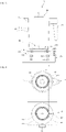
- FIG. 3 is a partial sectional view illustrating a part of blender configuration according to an embodiment of the disclosure
- FIG. 4 is a bottom view of a container body and a top view of a main body of the blender of FIG. 3 .
- the first induction coil 101 may be installed at the upper part of the main body 30.
- the first induction coil 101 may be embodied in a form in which a conductor is wound spirally multiple times on the same plane.
- the first induction coil 101 may be disposed in a form in which a conductor is spirally wound multiple times around a motor-side connection part 302 at the upper central part of the main body 30, in a ring shape as a whole.
- a light reception module 102 for receiving a light signal transmitted from outside may be installed.
- the light reception module 102 may be arranged to be exposed to the outside to receive the light signal.
- the light reception module 102 may be protected by a cover member (not shown) made of a light-transmitting material.
- the main body 30 may include a power supply part 103 inside.
- the power supply part 103 may apply current to the first induction coil 101. When the current is applied to the first induction coil 101, a magnetic field may be created in the first induction coil 101.
- the power supply part 103 may change the strength of the current applied to the first induction coil 101, and by the change of the current strength, the magnetic field may be changed in the first induction coil 101.
- the power supply part 103 may be mounted on a PCB substrate (not shown).
- the main body 30 may include a controller 104 inside.
- the controller 104 may be connected to the motor 51 which is for rotating the blade module 14.
- the controller 104 may drive the motor 51 when a light signal is received by the light reception module 102.
- the controller 104 may be mounted on a PCB substrate.
- the controller 104 may distinguish the container body 10 seated on the main body 30 by analyzing the light signal received by the light reception module 102, and may drive the motor 51 in an operation mode corresponding to the container body 10.
- distinguishing the container body 10 may mean to distinguish the type suitable for the purpose of the container body 10, thus the rotation speed of the motor 51 may be adjusted according to the purpose of the container body 10.
- the second induction coil 201 may be installed at the lower part of the container body 10.
- the second induction coil 201 may be arranged in a form in which a conductor is wound spirally multiple times on the same plane.
- the first induction coil 101 may be disposed in a form in which a conductor is spirally wound multiple times in an outer part around a blade-side connection part 142 at the lower central part of the container body 10, in a ring shape as a whole.
- the light source module 202 for receiving a light signal may be installed.
- the light source module 202 may be arranged to be exposed to the outside to transmit the light signal.
- the light source module 202 may be protected by a cover member (not shown) made of a light-transmitting material.
- the first induction coil 101 in the main body 30 and the second induction coil 201 in the container body 10 may be arranged at predetermined intervals at positions corresponding to each other.
- the first induction coil 101 and the second induction coil 201 may be respectively disposed to face and parallel to each other with the same center point.
- the first induction coil 101 and the second induction coil 201 may be selectively inductively coupled under certain conditions.
- the magnetic field in the first induction coil 101 may be changed and magnetic flux passing through the second induction coil 201 may be changed by the inductive coupling between the first induction coil 101 and the second induction coil 201, thus an induced electromotive force may be produced in the second induction coil 201.
- the induced electromotive force in the second induction coil 201 may be applied to the light source module 202.
- the light source module 202 may transmit the light signal by using the power applied from the second induction coil 201.
- the transmitted light signal may be received by the light reception module 102.
- the light source module 202 and the light reception module 102 may be arranged facing each other for smooth mutual transmission and reception of the light signal.
- the light source module 202 may include a light source that emits light, and the light reception module 102 may include a light sensor that detects the light emitted.
- the light source may include a light emitting diode (LED) and the light sensor may include a semiconductor sensor that can receive light.
- the semiconductor sensor may be implemented as, for example, a photodiode, a phototransistor, or the like.
- the main body 30 may have a seating detection module to detect whether the container body 10 is seated.
- the seating detection module may detect whether the container body 10 is seated by detecting a magnet installed in the lower part of the container body 10 when the container body 10 is seated on the main body 30.
- the seating detection module may include a reed switch, and when the magnet approaches the reed switch, the reed switch is turned on and detects the approach of the magnet, thereby detecting the seating of the container body 10.
- the voltage When a voltage is induced in the second induction coil 201, the voltage may be applied to the light source module 202.
- a conversion module may be included to convert an alternating current (AC) voltage generated in the second induction coil 201 to a direct current (DC) voltage required by the light source module 202.
- AC alternating current
- DC direct current
- the light source module 202 may modulate a frequency of a light signal and transmit the frequency-modulated light signal.
- the frequency modulation may be implemented differently for each container body 10.
- the embodiment it is able to analyze the frequency-modulated light signal and distinguish the container body 10 corresponding to the light signal.
- the conversion module may not be provided if the voltage generated in the second induction coil 201 can be used in the light source module 202 as it is.
- the conversion module may convert an AC voltage generated in the second induction coil 201 to a DC voltage required by the light source module 202 and supply the converted voltage.
- the motor 51 may be provided inside the main body 30, the motor 51 may be provided. The upper end of the motor 51 may be connected to the blade module 14 inside the container body 10.
- FIG. 5 is a partial sectional view illustrating a part of blender configuration according to another embodiment of the disclosure
- FIG. 6 is a bottom view of a container body and a top view of a main body of the blender of FIG. 5 .
- the first induction coil 101 may be installed at the upper part of the main body 30.
- the first induction coil 101 may be embodied in a form in which a conductor coil is wound spirally multiple times on the same plane.
- the first induction coil 101 may be disposed in a form in which a conductor is spirally wound multiple times on one side of a motor-side connection part 302 at the upper central part of the main body 30.
- the second induction coil 201 may be disposed in a form in which a conductor is spirally wound multiple times on one side of a blade-side connection part 142 at the lower central part of the container body 10.
- the first and second induction coils 101 and 201 may be arranged in a form in which their respective conductors are wound spirally multiple times on the same plane.
- the first induction coil 101 and the second induction coil 201 may be arranged at predetermined intervals to face each other.
- the first induction coil 101 and the second induction coil 201 may be arranged in order for the inductive coupling between the two coils to be effective.
- FIGS. 5 and 6 when compared to FIGS. 3 and 4 , the only difference is the respective installation location of the first and second induction coils 101 and 201, and the operation of the first induction coil 101, the light reception module 102, the power supply part 103, and the controller 104 of the main body 30, and the operation of the second induction coil 201 and the light source module 202 are the same. Therefore, redundant explanations are omitted.
- FIG. 7 is an equivalent circuit diagram of the blender according to embodiments of the disclosure.
- the first induction coil 101 may be connected to the power supply part 103 and the light reception module 102 may be connected to the controller 104 and the motor 51.
- the power supply part 103 supplies an alternating current to the first induction coil 101, and a magnetic field may be generated around the first induction coil 101 by the supplied alternating current in the first induction coil 101.
- the power supply part 103 adjusts the intensity of the alternating current supplied to the first induction coil 101, and thus may induce a change in the magnetic field of the first induction coil 101.
- the second induction coil 201 may be connected to the light source module 202.
- the conversion module 210 may be arranged between the second induction coil 201 and the light source module 202 as needed.
- the power supply part 103 may apply current to the first induction coil 101, by this current application, a magnetic field may be generated around the first induction coil 101.
- the power supply part 103 may alter the size of the current applied to the first induction coil 101, and by the alteration of the current size, the magnetic field may be changed.
- the first induction coil 101 in the main body 30 and the second induction coil 201 in the container body 10 may be placed corresponding to each other.
- inductive coupling between the first and second induction coils 101 and 201 occurs, and a voltage may be induced in the second induction coil 201 by the magnetic field generated in the first induction coil 101.
- the voltage induced in the second induction coil 201 may be applied to the conversion module 210.
- the conversion module 210 may convert a voltage induced in the second induction coil 201 to a voltage required by the light source module 202 at the rear end, and output the converted voltage.
- the voltage induced in the second induction coil 201 is an AC voltage, so the conversion module 210 may convert this to a DC voltage and output the converted DC voltage. Also, the conversion module 210 may adjust the magnitude of a voltage from the DC voltage converted to the DC voltage required for the light source of the light source module 202.
- the light reception module 102 in the main body 30 may receive the light signal.
- the controller 104 may analyze the light signal received by the light reception module 102 and distinguish the container body 10 seated on the main body 30 as described above, meaning it may distinguish the purpose or type of the container body 10.
- the light signal output from the light source module 202 may be set to be distinguished for each container body 10.
- the light signal received by the light reception module 102 may be used to distinguish the container body 10.
- the power supply part 103 may apply current to the first induction coil 101 before the container body 10 is seated on the main body 30.
- the power supply part 103 may apply current to the first induction coil 101 after the container body 10 is seated on the main body 30.
- the conversion module 210 may be provided optionally as needed. The conversion module 210 may not be provided if the light source module 202 generates a light signal using the induced voltage in the second induction coil 201.
- the voltage induced in the second induction coil 201 is an AC voltage and the voltage required by the light source module 202 is a DC voltage, so the conversion module 210 may be provided to convert the AC voltage to the DC voltage and adjust the magnitude of a voltage.
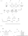
- FIG. 8 is a block diagram of a light source module according to embodiments of the disclosure
- FIG. 9 illustrates a frequency modulation of a light signal in the light source module.
- the light source module 202 may include a modulator 2021, a driver 2022, and a light source 2023.
- the light source 2023 may emit light.
- the light source 2023 may include a light emitting diode (LED), especially an infrared LED.
- LED light emitting diode
- the on-and-off state of the light source 2023 may be controlled by the driver 2022.
- the light source 2023 When the light source 2023 is in an on state it keeps emitting light, and when the light source 2023 is in an off state it may be turned off without emitting light.
- the light source 2023 may emit and be turned off repeatedly according to the on-and-off action.
- the light emitted from the light source 2023 may form a specific light signal according to the frequency being turned on and off.
- the modulator 2021 may modulate the frequency of a light signal. This modulation of the frequency of the light signal determines the cycle to turn on and off the light emission.
- FIG. 9 illustrates time at which light is turned on and off in the modulator 2021.
- the frequency of the light signal may be adjusted by adjusting the time at which light is turned on and off.
- the modulation of the frequency of the light signal may be determined depending on the container body 10.
- the driver 2022 may control on and off of the light source 2023 according to the frequency of the light signal.
- the light source 2023 may emit light by this on-and-off control.
- the light reception module 102 may receive the light emitted at a constant frequency from the light source 2023, and the controller 104 may analyze the received light signal, read the frequency of the light signal, and distinguish the container body 10.
- FIG. 10 is a flowchart illustrating the process by which a main body distinguishes a container body according to an embodiment of the disclosure.
- the container body 10 may be seated on the main body 30 in the embodiment.
- a seating detection module (not shown) for detecting the seating of the container body 10 on the main body 30 may be arranged in the main body 30.
- the seating detection module may detect the magnet attached to the container body 10, so when the container body 10 is seated on the main body 30, the seating detection module may detect the seating of the container body 10 by detecting the magnet and. [S101 : seating of container body]
- the power supply part 103 may apply a voltage to the first induction coil 101 when the magnet attached to the container body 10 is detected, and may apply an alternating current to the first induction coil 101.
- the power supply part 103 may also change the magnitude of the current applied to the first induction coil 101.
- the magnetic field created in the first induction coil 101 may affect the second induction coil 201. With this magnetic field, inductive coupling between the first and second induction coils 101, 201 may occur. [S105 : occurring of inductive coupling]
- a voltage may be induced in the second induction coil 201.
- an induced electromotive force may be generated in the second induction coil 201.
- the voltage induced in the second induction coil 201 may be supplied to the light source module 202.
- the light source module 202 does not operate until the voltage is supplied, and it may operate when the voltage is supplied.
- the light source 2023 inside may transmit a light signal.
- the light signal may emit light, but this may happen according to the set on and off.
- the light signal in the embodiment, may be set differently for each container body 10. That is, a specific light signal is set for each container body 10 so that the container body 10 may be distinguished by using the light signal.
- S109 supply voltage to light source module
- the light reception module 102 installed in the upper part of the main body 30 may receive the light signal.
- the light reception module 102 may transmit the light signal received from the light source module 202 to the controller 104.
- the controller 104 may analyze the received light signal.
- the container body 10 may be distinguished by analyzing the light signal. [S115 : analyze light signal]
- the controller 104 may distinguish the container body 10 by using the light signal analysis. [S117 : distinguish container body]
- controller 104 may drive the motor 51 in an operation mode suitable for the distinguished container body 10.
- FIG. 11 is a flowchart illustrating the process by which a main body distinguishes a container body according to another embodiment of the disclosure.
- a voltage may be induced in the second induction coil 201.
- the voltage induced in the second induction coil 201 may be applied to the light source module 102.
- the light source module 102 may be operated by the applied voltage.
- S201 apply voltage to light source module
- the modulator 2021 of the light source module 102 may modulate the frequency of the light signal.
- the modulation of the frequency of the light signal may include the process of determining the on-and-off period of light.
- the modulation of the frequency is to prevent other light from acting as noise on the light signal generated from the light source 2023 when light is used for other purposes in the blender 1.
- the light signal is modulated with a specific frequency for each container body 10, then by emitting light according to the frequency, it is able to distinguish the container body 10 according to the frequency while at the same time to be distinguished from the noise.
- S203 modulate frequency of light signal
- the driver 2022 of the light source module 202 may turn on and off the light source 2023 according to the modulated frequency.
- the light source 2023 may emit light by this on-and-off control, and the light source module 202 may transmit the frequency-modulated light signal to the outside.
- the light reception module 102 in the main body 30 may receive the light signal.
- the light source module 202 and the light reception module 102 may be placed corresponding to each other.
- the light reception module 102 is a device to receive a light signal and may include, for example, a semiconductor sensor.
- the semiconductor sensor may be implemented as, for example, a photodiode, a phototransistor, or the like. [S207 : receive light signal]
- the light signal received by the light reception module 102 may be transmitted to the controller 104.
- the controller 104 may analyze the received light signal. In this light signal analysis, the frequency of the light signal may be read. [S209 : analyze light signal]
- the frequency of the light signal is set for each container body 10, thus, it is able to distinguish the container body 10 by checking the frequency of the light signal.
- the controller 104 therefore, may distinguish the container body 10 by using the read frequency. [S211: distinguish container body]
- the main body 30 may operate in the operation mode suitable for the purpose of the container body 10.
- the frequency of the light signal may be modulated so that the light continues to emit.
- the frequency may be modulated so that the light stays on instead of repeating on and off periodically.
Landscapes
- Engineering & Computer Science (AREA)
- Mechanical Engineering (AREA)
- Food Science & Technology (AREA)
- Food-Manufacturing Devices (AREA)
Applications Claiming Priority (2)
| Application Number | Priority Date | Filing Date | Title |
|---|---|---|---|
| KR1020190098863A KR102805226B1 (ko) | 2019-08-13 | 2019-08-13 | 블렌더의 용기 구별방법 및 그 블렌더 |
| PCT/KR2020/010378 WO2021029610A1 (ko) | 2019-08-13 | 2020-08-06 | 블렌더의 용기 구별방법 및 그 블렌더 |
Publications (3)
| Publication Number | Publication Date |
|---|---|
| EP4014813A1 true EP4014813A1 (de) | 2022-06-22 |
| EP4014813A4 EP4014813A4 (de) | 2023-10-11 |
| EP4014813B1 EP4014813B1 (de) | 2025-10-29 |
Family
ID=74571110
Family Applications (1)
| Application Number | Title | Priority Date | Filing Date |
|---|---|---|---|
| EP20851475.2A Active EP4014813B1 (de) | 2019-08-13 | 2020-08-06 | Verfahren zur unterscheidung des behälters eines mischers und mischer |
Country Status (4)
| Country | Link |
|---|---|
| US (1) | US12324542B2 (de) |
| EP (1) | EP4014813B1 (de) |
| KR (1) | KR102805226B1 (de) |
| WO (1) | WO2021029610A1 (de) |
Family Cites Families (18)
| Publication number | Priority date | Publication date | Assignee | Title |
|---|---|---|---|---|
| US4371118A (en) * | 1980-06-02 | 1983-02-01 | Cuisinarts, Inc. | Magnetic safety interlock method and apparatus for food processor |
| DE3733108C1 (en) * | 1987-09-30 | 1989-02-23 | Bosch Siemens Hausgeraete | Circuit arrangement for a pot (saucepan) recognition system with a pot recognition sensor |
| JP2855929B2 (ja) * | 1992-01-14 | 1999-02-10 | 松下電器産業株式会社 | コードレス機器 |
| JPH06178734A (ja) * | 1992-12-15 | 1994-06-28 | Matsushita Electric Ind Co Ltd | 電動調理機 |
| KR0132984Y1 (ko) * | 1993-09-20 | 1998-12-01 | 김광호 | 복합형 조리기 |
| FR2791546B1 (fr) | 1999-04-02 | 2001-05-04 | Sagem | Appareil electromenager pour preparation alimentaire comportant un detecteur de couvercle en position de fermeture |
| US6320169B1 (en) * | 1999-09-07 | 2001-11-20 | Thermal Solutions, Inc. | Method and apparatus for magnetic induction heating using radio frequency identification of object to be heated |
| KR100796634B1 (ko) * | 2007-03-07 | 2008-01-22 | 주식회사 엔유씨전자 | 식품 가공장치 |
| US20100147832A1 (en) * | 2008-12-16 | 2010-06-17 | Barker Iii Charles R | Induction cookware identifying |
| DE102010027833A1 (de) * | 2010-04-15 | 2011-10-20 | E.G.O. Elektro-Gerätebau GmbH | Kochgefäß, Heizeinrichtung und Kochsystem |
| KR101420137B1 (ko) * | 2012-12-31 | 2014-07-24 | 서민호 | 용기 식별 기능을 가진 라면 조리기 |
| US20170095122A1 (en) | 2014-02-16 | 2017-04-06 | Breville Pty Limited | Combination Juicer Blender |
| US9981234B2 (en) * | 2014-03-20 | 2018-05-29 | Vita-Mix Management Corporation | Container/lid/blender interlock |
| DE102014115788A1 (de) * | 2014-10-30 | 2016-05-04 | Vorwerk & Co. Interholding Gmbh | Küchenmaschine mit Positionierungseinrichtung |
| EP3259051B1 (de) * | 2015-02-17 | 2022-05-04 | Vita-Mix Management Corporation | Mischsystem mit verriegelungen |
| CN109843123B (zh) * | 2016-11-08 | 2023-02-17 | 雀巢产品有限公司 | 饮料或食品制备系统 |
| US11013371B2 (en) | 2017-03-10 | 2021-05-25 | Vita-Mix Management Corporation | Wireless food processor discs |
| WO2020191437A1 (en) * | 2019-03-25 | 2020-10-01 | Breville Pty Limited | Kitchen device |
-
2019
- 2019-08-13 KR KR1020190098863A patent/KR102805226B1/ko active Active
-
2020
- 2020-08-06 US US17/612,828 patent/US12324542B2/en active Active
- 2020-08-06 WO PCT/KR2020/010378 patent/WO2021029610A1/ko not_active Ceased
- 2020-08-06 EP EP20851475.2A patent/EP4014813B1/de active Active
Also Published As
| Publication number | Publication date |
|---|---|
| EP4014813A4 (de) | 2023-10-11 |
| KR20210019795A (ko) | 2021-02-23 |
| KR102805226B1 (ko) | 2025-05-12 |
| US20220218155A1 (en) | 2022-07-14 |
| US12324542B2 (en) | 2025-06-10 |
| WO2021029610A1 (ko) | 2021-02-18 |
| EP4014813B1 (de) | 2025-10-29 |
Similar Documents
| Publication | Publication Date | Title |
|---|---|---|
| US12268335B2 (en) | Kitchen device | |
| JP6008139B2 (ja) | 非接触給電装置および非接触電力伝送システム | |
| EP2548636B1 (de) | Herd mit betätigungsmitteln zur betätigung von drehschaufeln und anordnung mit einem herd und einem küchengefäss mit drehschaufeln | |
| JP4162577B2 (ja) | 加熱調理器およびその加熱調理器に用いられる調理器具 | |
| JP4086187B2 (ja) | 電気器具の操作装置 | |
| CN107852784B (zh) | 感应加热烹调器及其控制方法 | |
| EP3536199A1 (de) | Elektrischer split-dampfdruckkochtopf | |
| EP2583750A1 (de) | Küchenarbeitsplatte mit drehbaren betätigungsmitteln und kochbehälter zur verwendung auf dieser arbeitsplatte | |
| CN111657761A (zh) | 电动搅拌容器 | |
| JP2010049959A (ja) | 誘導加熱調理器 | |
| AU2020328375B2 (en) | Blender | |
| KR20220117656A (ko) | 조리 기기, 조리 기기의 제어 방법 및 조리 기기를 제어 가능한 노브 | |
| EP4014813B1 (de) | Verfahren zur unterscheidung des behälters eines mischers und mischer | |
| JP2009133501A (ja) | 温度検出ユニット | |
| JP2009093805A (ja) | 加熱調理システムおよび加熱調理器 | |
| EP4014820A1 (de) | Mixer | |
| US20220399756A1 (en) | Noncontact power supply device and control device therefor | |
| US12527438B2 (en) | Blender | |
| JP2009087743A (ja) | 加熱調理システム、加熱調理システムに用いられる加熱調理器および調理器具 | |
| US12532988B2 (en) | Blender | |
| JP2009093804A (ja) | 調理器具 | |
| JP4280167B2 (ja) | 加熱調理のシステム | |
| EP4095879B1 (de) | Steuerschaltung zur verhinderung eines unbeaufsichtigten starts eines motors eines gerätes | |
| JPH0367486A (ja) | 誘導加熱調理器 | |
| JP2012249718A (ja) | 電気炊飯器 |
Legal Events
| Date | Code | Title | Description |
|---|---|---|---|
| STAA | Information on the status of an ep patent application or granted ep patent |
Free format text: STATUS: THE INTERNATIONAL PUBLICATION HAS BEEN MADE |
|
| PUAI | Public reference made under article 153(3) epc to a published international application that has entered the european phase |
Free format text: ORIGINAL CODE: 0009012 |
|
| STAA | Information on the status of an ep patent application or granted ep patent |
Free format text: STATUS: REQUEST FOR EXAMINATION WAS MADE |
|
| 17P | Request for examination filed |
Effective date: 20220124 |
|
| AK | Designated contracting states |
Kind code of ref document: A1 Designated state(s): AL AT BE BG CH CY CZ DE DK EE ES FI FR GB GR HR HU IE IS IT LI LT LU LV MC MK MT NL NO PL PT RO RS SE SI SK SM TR |
|
| DAV | Request for validation of the european patent (deleted) | ||
| DAX | Request for extension of the european patent (deleted) | ||
| A4 | Supplementary search report drawn up and despatched |
Effective date: 20230907 |
|
| RIC1 | Information provided on ipc code assigned before grant |
Ipc: A47J 43/046 20060101ALI20230901BHEP Ipc: A47J 43/07 20060101AFI20230901BHEP |
|
| GRAP | Despatch of communication of intention to grant a patent |
Free format text: ORIGINAL CODE: EPIDOSNIGR1 |
|
| STAA | Information on the status of an ep patent application or granted ep patent |
Free format text: STATUS: GRANT OF PATENT IS INTENDED |
|
| INTG | Intention to grant announced |
Effective date: 20250611 |
|
| GRAS | Grant fee paid |
Free format text: ORIGINAL CODE: EPIDOSNIGR3 |
|
| GRAA | (expected) grant |
Free format text: ORIGINAL CODE: 0009210 |
|
| STAA | Information on the status of an ep patent application or granted ep patent |
Free format text: STATUS: THE PATENT HAS BEEN GRANTED |
|
| AK | Designated contracting states |
Kind code of ref document: B1 Designated state(s): AL AT BE BG CH CY CZ DE DK EE ES FI FR GB GR HR HU IE IS IT LI LT LU LV MC MK MT NL NO PL PT RO RS SE SI SK SM TR |
|
| REG | Reference to a national code |
Ref country code: CH Ref legal event code: F10 Free format text: ST27 STATUS EVENT CODE: U-0-0-F10-F00 (AS PROVIDED BY THE NATIONAL OFFICE) Effective date: 20251029 Ref country code: GB Ref legal event code: FG4D |
|
| REG | Reference to a national code |
Ref country code: IE Ref legal event code: FG4D |
|
| REG | Reference to a national code |
Ref country code: DE Ref legal event code: R096 Ref document number: 602020061378 Country of ref document: DE |
|
| REG | Reference to a national code |
Ref country code: NL Ref legal event code: MP Effective date: 20251029 |
|
| PG25 | Lapsed in a contracting state [announced via postgrant information from national office to epo] |
Ref country code: ES Free format text: LAPSE BECAUSE OF FAILURE TO SUBMIT A TRANSLATION OF THE DESCRIPTION OR TO PAY THE FEE WITHIN THE PRESCRIBED TIME-LIMIT Effective date: 20251029 |
|
| REG | Reference to a national code |
Ref country code: LT Ref legal event code: MG9D |
|
| PG25 | Lapsed in a contracting state [announced via postgrant information from national office to epo] |
Ref country code: NO Free format text: LAPSE BECAUSE OF FAILURE TO SUBMIT A TRANSLATION OF THE DESCRIPTION OR TO PAY THE FEE WITHIN THE PRESCRIBED TIME-LIMIT Effective date: 20260129 |
|
| PG25 | Lapsed in a contracting state [announced via postgrant information from national office to epo] |
Ref country code: HR Free format text: LAPSE BECAUSE OF FAILURE TO SUBMIT A TRANSLATION OF THE DESCRIPTION OR TO PAY THE FEE WITHIN THE PRESCRIBED TIME-LIMIT Effective date: 20251029 Ref country code: FI Free format text: LAPSE BECAUSE OF FAILURE TO SUBMIT A TRANSLATION OF THE DESCRIPTION OR TO PAY THE FEE WITHIN THE PRESCRIBED TIME-LIMIT Effective date: 20251029 Ref country code: AT Free format text: LAPSE BECAUSE OF FAILURE TO SUBMIT A TRANSLATION OF THE DESCRIPTION OR TO PAY THE FEE WITHIN THE PRESCRIBED TIME-LIMIT Effective date: 20251029 |
|
| REG | Reference to a national code |
Ref country code: AT Ref legal event code: MK05 Ref document number: 1850613 Country of ref document: AT Kind code of ref document: T Effective date: 20251029 |
|
| PG25 | Lapsed in a contracting state [announced via postgrant information from national office to epo] |
Ref country code: NL Free format text: LAPSE BECAUSE OF FAILURE TO SUBMIT A TRANSLATION OF THE DESCRIPTION OR TO PAY THE FEE WITHIN THE PRESCRIBED TIME-LIMIT Effective date: 20251029 |
|
| PG25 | Lapsed in a contracting state [announced via postgrant information from national office to epo] |
Ref country code: RS Free format text: LAPSE BECAUSE OF FAILURE TO SUBMIT A TRANSLATION OF THE DESCRIPTION OR TO PAY THE FEE WITHIN THE PRESCRIBED TIME-LIMIT Effective date: 20260129 |
|
| PG25 | Lapsed in a contracting state [announced via postgrant information from national office to epo] |
Ref country code: IS Free format text: LAPSE BECAUSE OF FAILURE TO SUBMIT A TRANSLATION OF THE DESCRIPTION OR TO PAY THE FEE WITHIN THE PRESCRIBED TIME-LIMIT Effective date: 20260228 |
|
| PG25 | Lapsed in a contracting state [announced via postgrant information from national office to epo] |
Ref country code: PT Free format text: LAPSE BECAUSE OF FAILURE TO SUBMIT A TRANSLATION OF THE DESCRIPTION OR TO PAY THE FEE WITHIN THE PRESCRIBED TIME-LIMIT Effective date: 20260302 |
|
| PG25 | Lapsed in a contracting state [announced via postgrant information from national office to epo] |
Ref country code: PL Free format text: LAPSE BECAUSE OF FAILURE TO SUBMIT A TRANSLATION OF THE DESCRIPTION OR TO PAY THE FEE WITHIN THE PRESCRIBED TIME-LIMIT Effective date: 20251029 |
|
| PG25 | Lapsed in a contracting state [announced via postgrant information from national office to epo] |
Ref country code: LV Free format text: LAPSE BECAUSE OF FAILURE TO SUBMIT A TRANSLATION OF THE DESCRIPTION OR TO PAY THE FEE WITHIN THE PRESCRIBED TIME-LIMIT Effective date: 20251029 |