EP4014859A1 - Abtastsonde für optische kohärenztomografie - Google Patents
Abtastsonde für optische kohärenztomografie Download PDFInfo
- Publication number
- EP4014859A1 EP4014859A1 EP21215065.0A EP21215065A EP4014859A1 EP 4014859 A1 EP4014859 A1 EP 4014859A1 EP 21215065 A EP21215065 A EP 21215065A EP 4014859 A1 EP4014859 A1 EP 4014859A1
- Authority
- EP
- European Patent Office
- Prior art keywords
- tubular housing
- scanning probe
- optical fiber
- localization
- transmittable portion
- Prior art date
- Legal status (The legal status is an assumption and is not a legal conclusion. Google has not performed a legal analysis and makes no representation as to the accuracy of the status listed.)
- Granted
Links
Images




Classifications
-
- A—HUMAN NECESSITIES
- A61—MEDICAL OR VETERINARY SCIENCE; HYGIENE
- A61B—DIAGNOSIS; SURGERY; IDENTIFICATION
- A61B5/00—Measuring for diagnostic purposes; Identification of persons
- A61B5/0059—Measuring for diagnostic purposes; Identification of persons using light, e.g. diagnosis by transillumination, diascopy, fluorescence
- A61B5/0062—Arrangements for scanning
- A61B5/0066—Optical coherence imaging
-
- A—HUMAN NECESSITIES
- A61—MEDICAL OR VETERINARY SCIENCE; HYGIENE
- A61B—DIAGNOSIS; SURGERY; IDENTIFICATION
- A61B5/00—Measuring for diagnostic purposes; Identification of persons
- A61B5/0033—Features or image-related aspects of imaging apparatus, e.g. for MRI, optical tomography or impedance tomography apparatus; Arrangements of imaging apparatus in a room
- A61B5/0036—Features or image-related aspects of imaging apparatus, e.g. for MRI, optical tomography or impedance tomography apparatus; Arrangements of imaging apparatus in a room including treatment, e.g., using an implantable medical device, ablating, ventilating
-
- A—HUMAN NECESSITIES
- A61—MEDICAL OR VETERINARY SCIENCE; HYGIENE
- A61B—DIAGNOSIS; SURGERY; IDENTIFICATION
- A61B5/00—Measuring for diagnostic purposes; Identification of persons
- A61B5/0033—Features or image-related aspects of imaging apparatus, e.g. for MRI, optical tomography or impedance tomography apparatus; Arrangements of imaging apparatus in a room
- A61B5/004—Features or image-related aspects of imaging apparatus, e.g. for MRI, optical tomography or impedance tomography apparatus; Arrangements of imaging apparatus in a room adapted for image acquisition of a particular organ or body part
- A61B5/0042—Features or image-related aspects of imaging apparatus, e.g. for MRI, optical tomography or impedance tomography apparatus; Arrangements of imaging apparatus in a room adapted for image acquisition of a particular organ or body part for the brain
-
- A—HUMAN NECESSITIES
- A61—MEDICAL OR VETERINARY SCIENCE; HYGIENE
- A61B—DIAGNOSIS; SURGERY; IDENTIFICATION
- A61B5/00—Measuring for diagnostic purposes; Identification of persons
- A61B5/06—Devices, other than using radiation, for detecting or locating foreign bodies ; Determining position of diagnostic devices within or on the body of the patient
- A61B5/065—Determining position of the probe employing exclusively positioning means located on or in the probe, e.g. using position sensors arranged on the probe
- A61B5/066—Superposing sensor position on an image of the patient, e.g. obtained by ultrasound or x-ray imaging
-
- A—HUMAN NECESSITIES
- A61—MEDICAL OR VETERINARY SCIENCE; HYGIENE
- A61B—DIAGNOSIS; SURGERY; IDENTIFICATION
- A61B5/00—Measuring for diagnostic purposes; Identification of persons
- A61B5/68—Arrangements of detecting, measuring or recording means, e.g. sensors, in relation to patient
- A61B5/6846—Arrangements of detecting, measuring or recording means, e.g. sensors, in relation to patient specially adapted to be brought in contact with an internal body part, i.e. invasive
- A61B5/6867—Arrangements of detecting, measuring or recording means, e.g. sensors, in relation to patient specially adapted to be brought in contact with an internal body part, i.e. invasive specially adapted to be attached or implanted in a specific body part
- A61B5/6868—Brain
-
- A—HUMAN NECESSITIES
- A61—MEDICAL OR VETERINARY SCIENCE; HYGIENE
- A61N—ELECTROTHERAPY; MAGNETOTHERAPY; RADIATION THERAPY; ULTRASOUND THERAPY
- A61N1/00—Electrotherapy; Circuits therefor
- A61N1/02—Details
- A61N1/04—Electrodes
- A61N1/05—Electrodes for implantation or insertion into the body, e.g. heart electrode
- A61N1/0526—Head electrodes
- A61N1/0529—Electrodes for brain stimulation
- A61N1/0534—Electrodes for deep brain stimulation
-
- A—HUMAN NECESSITIES
- A61—MEDICAL OR VETERINARY SCIENCE; HYGIENE
- A61B—DIAGNOSIS; SURGERY; IDENTIFICATION
- A61B2562/00—Details of sensors; Constructional details of sensor housings or probes; Accessories for sensors
- A61B2562/22—Arrangements of medical sensors with cables or leads; Connectors or couplings specifically adapted for medical sensors
- A61B2562/221—Arrangements of sensors with cables or leads, e.g. cable harnesses
- A61B2562/222—Electrical cables or leads therefor, e.g. coaxial cables or ribbon cables
-
- A—HUMAN NECESSITIES
- A61—MEDICAL OR VETERINARY SCIENCE; HYGIENE
- A61B—DIAGNOSIS; SURGERY; IDENTIFICATION
- A61B5/00—Measuring for diagnostic purposes; Identification of persons
- A61B5/68—Arrangements of detecting, measuring or recording means, e.g. sensors, in relation to patient
- A61B5/6846—Arrangements of detecting, measuring or recording means, e.g. sensors, in relation to patient specially adapted to be brought in contact with an internal body part, i.e. invasive
- A61B5/6847—Arrangements of detecting, measuring or recording means, e.g. sensors, in relation to patient specially adapted to be brought in contact with an internal body part, i.e. invasive mounted on an invasive device
- A61B5/686—Permanently implanted devices, e.g. pacemakers, other stimulators, biochips
-
- A—HUMAN NECESSITIES
- A61—MEDICAL OR VETERINARY SCIENCE; HYGIENE
- A61N—ELECTROTHERAPY; MAGNETOTHERAPY; RADIATION THERAPY; ULTRASOUND THERAPY
- A61N1/00—Electrotherapy; Circuits therefor
- A61N1/18—Applying electric currents by contact electrodes
- A61N1/32—Applying electric currents by contact electrodes alternating or intermittent currents
- A61N1/36—Applying electric currents by contact electrodes alternating or intermittent currents for stimulation
- A61N1/3605—Implantable neurostimulators for stimulating central or peripheral nerve system
- A61N1/3606—Implantable neurostimulators for stimulating central or peripheral nerve system adapted for a particular treatment
- A61N1/36067—Movement disorders, e.g. tremor or Parkinson disease
Definitions
- This present disclosure relates to an optical coherence tomography (OCT) scanning probe.
- OCT optical coherence tomography
- DBS deep brain stimulation
- STN subthalamic nucleus
- a medical device which sends electrical current to effect the physiology of brain cells and neurotransmitters, such that dyskinesia can be well controlled and movement of patient's limbs can be improved.
- DBS generally includes the following procedures: (1) DBS target localization procedure; and (2) DBS electrode implantation procedure.
- a magnetic resonance imaging (MRI) of patient's head is firstly performed for surgical path planning; then, a microelectrode recording (MER) probe is inserted into patient's head along the predetermined surgical path for detecting physiological signals of brain cells to determine the location of surgical target.
- a permanent DBS lead is implanted according the location of surgical target.
- the conventional DBS suffers some problems related to inaccurate localization in the target localization procedure.
- MRI and MER help to confirm the location of surgical target. It is difficult for surgeons to identify surgical target (STN or internal globus pallidus) from MRI images due to small size of the surgical target. Also, inevitable brain shift caused by cerebrospinal fluid leakage and intracranial pressure may change the location of surgical target.
- MER merely provides one dimensional spatial information (for example, information along an insertion direction of the microelectrode).
- the present disclosure provides an optical coherent tomography probe suitable for DBS, which helps to solve the problem that the target cannot be accurately positioned before the surgery or the electrode position cannot be accurately located during the surgery.
- an OCT scanning probe includes a tubular housing, at least one electrode, an optical fiber scanner and an auxiliary localization component.
- the electrode is disposed on an outer surface of the tubular housing.
- the optical fiber scanner is disposed in the tubular housing.
- the optical fiber scanner includes an optical fiber and an optical element.
- the optical element is disposed on an emitting end of the optical fiber, and the optical element is at corresponding position to a light transmittable portion of the tubular housing.
- the auxiliary localization component is disposed on the tubular housing, and the auxiliary localization component overlaps part of the light transmittable portion.
- a light beam emitted from the optical fiber scanner passes through the light transmittable portion to obtain a tomographic image.
- An interaction of part of the light beam with the auxiliary localization component causes a characteristic in the tomographic image, with the characteristic corresponding to the auxiliary localization component.
- an auxiliary localization component overlaps a light transmittable portion of a tubular housing, such that a light beam emitted from an optical fiber scanner is blocked or reflected by the auxiliary localization component when passing through the light transmittable portion, thereby causing a characteristic (dark zone or bright zone) in a tomographic image.
- the location of the OCT scanning probe with respect to a surgical target can be determined according to the characteristic.
- the OCT scanning probe helps to position the target or determine whether the electrode is at the central region of the target. Once there is an offset between the electrode and the central region of the target, a surgeon can adjust a DBS lead implantation path according to the tomographic image, which is helpful to improve the therapeutic effect of DBS.
- an OCT scanning probe includes tubular housing, electrode, optical fiber scanner and auxiliary localization component.
- FIG. 1 is a schematic view of an OCT scanning probe according to a first embodiment of the present disclosure.
- the OCT scanning probe 1a includes a tubular housing 10, an electrode 20, an optical fiber scanner 30 and an auxiliary localization component 40.
- the tubular housing 10 for example, is a glass tube including a light transmittable portion 110 and an opaque portion 120, but the present disclosure is not limited thereto; in some embodiments, the tubular housing 10 may be made of light transmittable material such as glass, such that every portion of the tubular housing 10 is light transmittable. In this embodiment, the light transmittable portion 110 is located on a side wall of the tubular housing 10, but the present disclosure is not limited to specific location of the light transmittable portion 110.
- the electrode 20, for example, is an electrode ring disposed on an outer surface of the tubular housing 10.
- the tubular housing 10 and the electrode 20 jointly constitute a DBS electrode.
- the electrode 20 can be electrically connected with external power supply (not shown in the drawings) for activating tissues, such as brain tissue, outside the OCT scanning probe 1a.
- external power supply not shown in the drawings
- FIG. 1 there are multiple electrodes 20 on the tubular housing 10, but the present disclosure is not limited to the number of electrode 20; in some embodiments, single electrode 20 may be provided for measurement.
- the electrode 20 can be turned on to activate brain tissues or measure electrophysiological recordings of brain cells.
- the optical fiber scanner 30 is disposed in the tubular housing 10, and the optical fiber scanner 30 includes a base 310, an optical fiber 320 and an optical element 330a.
- the optical fiber 320 is disposed on the base 310, and the optical element 330a is at corresponding position to the light transmittable portion 110 of the tubular housing 10.
- the base 310 is rotatably disposed in the tubular housing 10.
- the base 310 brings the optical fiber 320 to together rotate about a central axis of the base 310 with respect to the tubular housing 10; in some embodiments, the optical fiber 320 rotatably disposed in the base 310, and the optical fiber 320 can be used for scanning due to its rotation with respect to the base 310.
- the optical fiber 320 further includes an emitting end 321 of the optical fiber 320, and the optical element 330a is disposed on the emitting end 321. Since the light transmittable portion 110 is located on the side wall of the tubular housing 10, the optical element 330a in this embodiment may be a reflector for changing a traveling direction of light beam emitted from the optical fiber 320. Said light beam from the optical fiber 320 can be reflected by the optical element 330a, and then travels through the light transmittable portion 110 to the outside of the OCT scanning probe 1a.
- the light beam reaches tissues outside the OCT scanning probe 1a, and the light beam is reflected by the tissues so as to be received by image sensor (not shown in the drawings) connected to the end of the optical fiber 320, and thus the image sensor generates one or more tomographic images.
- image sensor not shown in the drawings
- the present disclosure is not limited to the reflector working with the optical element 330a in this embodiment; in some embodiments, suitable optical component can be selected as the optical element 330a according to the location of the light transmittable portion, and the present disclosure is not limited to example(s) mentioned above.
- the optical fiber scanner 30 is detachably sleeved in the tubular housing 10 so as to be removable from the tubular housing 10, and the optical fiber scanner 30 is movable along the central axis of the tubular housing 10, but the present disclosure is not limited thereto; in some embodiments, the optical fiber scanner 30 may be fixed inside the tubular housing 10.
- said "light transmittable portion" of the tubular housing refers to a portion which is transmittable to the light beam emitted from the optical fiber.
- the light transmittable portion is transmittable to light having visible wavelengths; as the light beam emitted from the optical fiber is infrared light, the light transmittable portion is transmittable to light having infrared wavelengths.
- the auxiliary localization component 40 is disposed on the tubular housing 10, and the auxiliary localization component 40 overlaps part of the light transmittable portion 110.
- the auxiliary localization component 40 for example, is a conductive line inside the side wall of the tubular housing 10, and the conductive line is electrically connected with the electrodes 20.
- the auxiliary localization component 40 can be electrically connected with external power supply (now shown in the drawings) to deliver electricity to the electrode 20, thereby activating tissues outside the OCT scanning probe 1a.
- the present disclosure is not limited to the electrical connection between the auxiliary localization component 40 and the electrode 20.
- the auxiliary localization component 40 is nonconductive and insulated from the electrode 20, with additional conductive line provided to be electrically connected with the electrode 20.
- auxiliary localization component 40 overlaps part of the light transmittable portion 110, some amount of light in the light beam interacts with the auxiliary localization component 40, thereby causing a characteristic in the aforementioned tomographic image, with the characteristic corresponding to the auxiliary localization component 40. Details about the interaction of auxiliary localization component and the characteristic in tomographic image will be described hereafter.
- the OCT scanning probe 1a further includes an indicating component 50 disposed on the outer surface of the tubular housing 10, and the indicating component 50 has a mark 510 at a direction corresponding to the auxiliary localization component 40.
- the indicating component 50 may be an annular block mounted on the outer surface of the tubular housing 10, and the mark 510 may be protrusion, recess, letter symbol, pattern or combination thereof.
- the auxiliary localization component 40 and the mark 510 are aligned, such that the orientation of the auxiliary localization component 40 can be determined by viewing the mark 510.
- an OCT scanning probe 1b includes a tubular housing 10b, a plurality of electrodes 20, an optical fiber scanner 30b, an auxiliary localization component 40b and an indicating component 50.
- an OCT scanning probe 1b includes a tubular housing 10b, a plurality of electrodes 20, an optical fiber scanner 30b, an auxiliary localization component 40b and an indicating component 50.
- any detail can be referred to the foregoing description of corresponding component in FIG. 1 , and any detail description about the electrode 20 and the indicating component 50 will be omitted hereafter.
- the tubular housing 10b includes a light transmittable portion 110b and an opaque portion 120.
- the light transmittable portion 110b of the tubular housing 100b is located on a closed end of the tubular housing 100b.
- the size of the light transmittable portion 110b depends on specifications of the optical fiber for scanning, and the present disclosure is not limited to the light transmittable portion 110b in the drawings.
- the optical element 330b of the optical fiber scanner 30b may be a focusing lens configured to converge light beam emitted from the optical fiber 320, and the converged light beam reaches outside of the OCT scanning probe 1b through the light transmittable portion 110b.
- auxiliary localization component 40b is disposed on the tubular housing 10b, and the auxiliary localization component 40b overlaps part of the light transmittable portion 110b.
- auxiliary localization component 40b for example, is a conductive line electrically connected with the electrodes 20, and extends to the closed end of the tubular housing 100b, thereby covering part of the light transmittable portion 110b.
- the auxiliary localization component 40b may be a nonconductive line mark, and it covers part of the light transmittable portion 110b.
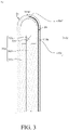
- an OCT scanning probe 1c includes a tubular housing 10c, an electrode 20, an optical fiber scanner 30c and an auxiliary localization component 40c.
- the electrode 20 in FIG. 3 any detail can be referred to the foregoing description of corresponding component in FIG. 1 , and any detail description about the electrode 20 will be omitted hereafter.
- an indicating component located on the outer surface of the tubular housing is omitted in FIG. 3 .
- the tubular housing 10c includes a first light transmittable portion 110c and a second light transmittable portion 110c'.
- the first light transmittable portion 110c is located on the side wall of the tubular housing 10c, and the second light transmittable portion 110c' is located on a closed end of the tubular housing 10c.
- the rest of the tubular housing 10 may be light transmittable or opaque.
- the optical fiber scanner 30c includes a base 310, an optical fiber 320 and an optical element 330c.
- the base 310 is rotatably disposed in the tubular housing 10c, and the optical fiber 320 is disposed on the base 310.
- the optical element 330c is disposed on the emitting end 321 of the optical fiber 320.
- the optical element 330c may be a beam splitter in this embodiment.
- the optical element 330c corresponds to the first light transmittable portion 110c and the second light transmittable portion 110c'.
- the optical element 330c is configured to split the light beam emitted from the optical fiber 320 into a first sub-beam traveling toward the first light transmittable portion 110c and a second sub-beam traveling toward the second light transmittable portion 110c'.
- the two sub-beams pass through the first light transmittable portion 110c and the second light transmittable portion 110c', respectively, to reach outside of the OCT scanning probe 1c.
- the two sub-beams can illuminate different regions of a tissue outside the OCT scanning probe 1c, and an image sensor (not shown in the drawings) can receive the first and second sub-beams to obtain one or more tomographic images
- the auxiliary localization component 40c is disposed on the tubular housing 10c, and includes a first localization member 410c and a second localization member 420c.
- the first localization member 410c overlaps part of the first light transmittable portion 110c
- second localization member 420c overlaps part of the second light transmittable portion 110c'.
- the first localization member 410c for example, is a conductive line disposed in the side wall of the tubular housing 10c and electrically connected with the electrode 20.
- the first localization member 410c may be electrically connected with external power supply (not shown in the drawings) for supplying electricity to the electrode 20.
- the second localization member 420c is disposed on the closed end of the tubular housing 10c and electrically connected with the electrode 20.
- each of the first localization member 410c and the second localization member 420c of the auxiliary localization component 40c may be a nonconductive line mark covering part of the first light transmittable portion 110c and part of the second light transmittable portion 110c', respectively.
- the first localization member 410c overlaps part of the first light transmittable portion 110c and the second light transmittable portion 110c' overlaps part of the second localization member 420c, some amount of light in the light beam interacts with the auxiliary localization component 40c, thereby causing characteristics in a tomographic image, with one characteristic corresponding to the first localization member 410c and another characteristic corresponding to the second localization member 420c.
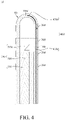
- an OCT scanning probe 1d includes a tubular housing 10c, a plurality of electrodes 20d, an optical fiber scanner 30c and an auxiliary localization component 40d.
- a tubular housing 10c and the optical fiber scanner 30c in FIG. 4 any detail can be referred to the foregoing description of corresponding component in FIG. 3 , and any detail description about the tubular housing 10c and the optical fiber scanner 30c will be omitted hereafter.
- an indicating component located on the outer surface of the tubular housing is omitted in FIG. 4 .
- Each of the electrodes 20d is an annular electrode ring disposed on the outer surface of the tubular housing 10c.
- the auxiliary localization component 40d includes a plurality of localization members which are at different positions of the tubular housing 10c.
- the auxiliary localization component 40d includes a plurality of first localization members 410d and a second localization member 420d.
- FIG. 4 exemplarily shows one of the first localization members 410d.
- each of the first localization members 410d overlaps part of the first light transmittable portion 110c of the tubular housing 10c, and the second localization member 420d overlaps part of the second light transmittable portion 110c'.
- each of the first localization members 410d for example, is a conductive line disposed in the side wall of the tubular housing 10c and electrically connected with respective electrode 20d.
- the first localization member 410d can be electrically connected with external power supply (now shown in the drawings) to deliver electricity to the electrode 20d.
- the second localization member 420d is disposed on the closed end of the tubular housing 10c and electrically connected with the electrode 20d.
- both the first localization member 410d and the second localization member 420d of the auxiliary localization component 40d may be nonconductive line marks or printed patterns which cover part of the first light transmittable portion 110c and part of the second light transmittable portion 110c'.
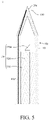
- an OCT scanning probe 1e includes a tubular housing 10e, an electrode 20e, an optical fiber scanner 30 and an auxiliary localization component 40e.
- the optical fiber scanner 30 in FIG. 5 any detail can be referred to the foregoing description of corresponding component in FIG. 1 , and any detail description about the optical fiber scanner 30 will be omitted hereafter.
- an indicating component located on the outer surface of the tubular housing is omitted in FIG. 5 .
- the tubular housing 10e for example, is a transparent glass tube includes a light transmittable portion 110 on its side wall. Furthermore, the tubular housing 10e further includes a tapered end 130. The electrode 20e is disposed on the tapered end 130 of the tubular housing 10e, and the electrode 20e is located on the outer surface of the tubular housing 10e. In one embodiment, the tubular housing 10e and the electrode 20e can jointly work as a probe for measuring electrophysiological recordings of brain cells, and the electrode 20e substantially has the same size as human neuron.
- the auxiliary localization component 40e is disposed on the tubular housing 10e, and the auxiliary localization component 40 overlaps part of the light transmittable portion 110.
- the auxiliary localization component 40e for example, is a conductive line disposed in the side wall of the tubular housing 10e and electrically connected with the electrode 20e.
- the auxiliary localization component 40e can be electrically connected with external power supply (now shown in the drawings) to deliver electricity to the electrode 20e.
- an OCT scanning probe If includes a tubular housing 10e, a plurality of electrodes 20f, an optical fiber scanner 30 and an auxiliary localization component 40f.
- a tubular housing 10e and the optical fiber scanner 30 in FIG. 6 any detail can be referred to the foregoing description of corresponding component in FIG. 1 and FIG. 5 , and any detail description about the tubular housing 10e and the optical fiber scanner 30 will be omitted hereafter.
- an indicating component located on the outer surface of the tubular housing is omitted in FIG. 6 .
- the electrode 20f includes a first electrode 210f and a second electrode 220f.
- the first electrode 210f for example, is an annular electrode ring disposed on the outer surface of the tubular housing 10e.
- the second electrode 220f is disposed on a tapered end 130 of the tubular housing 10e, and the second electrode 220f is disposed on disposed on the outer surface of the tubular housing 10e.
- the auxiliary localization component 40f is disposed on the tubular housing 10e, and the auxiliary localization component 40f includes a first localization member 410f and a second localization member 420f.
- the first localization member 410f and the second localization member 420f overlap parts of a light transmittable portion 110 of the tubular housing 10e.
- the first localization member 410f is disposed in the side wall of the tubular housing 10e and electrically connected with the first electrode 210f.
- the second localization member 420f is disposed in the side wall of the tubular housing 10e and electrically connected with the second electrode 220f.
- the first localization member 410f and the second localization member 420f can deliver electricity to the first electrode 210f and the second electrode 220f, respectively.
- both the first localization member 410f and the second localization member 420f enclose an angle of 180 degrees with respect to an axis of the tubular housing 10e; in another embodiment, both the first localization member 410f and the second localization member 420f enclose an angle of 90 degrees with respect to the axis of the tubular housing 10e.
- the present disclosure is not limited to the aforementioned angle value between the localization member and the axis of the tubular housing.
- FIG. 7 showing a schematic view of an OCT scanning probe according to a seventh embodiment of the present disclosure.
- An OCT scanning probe 1g includes a tubular housing 10c, a plurality of electrodes 20g, an optical fiber scanner 30c and an auxiliary localization component 40g.
- any detail can be referred to the foregoing description of corresponding component in FIG. 4 , and any detail description about the tubular housing 10c and the optical fiber scanner 30c will be omitted hereafter.
- an indicating component located on the outer surface of the tubular housing is omitted in FIG. 7 .
- the electrodes 20g includes a plurality of first electrodes 210g and a second electrode 220g.
- Each of the first electrodes 210g for example, is an electrode ring disposed on the outer surface of the tubular housing 10c.
- the first electrode 210g is identical to the electrode 20d in FIG. 4 , and will not go into details hereafter.
- the second electrode 220g is disposed on a hemispherical closed end of the tubular housing 10c, and the second electrode 220g is located on the outer surface of the tubular housing 10c.
- the second electrode 220g is a tip of the electrodes 20g extending outward from the outer surface of the tubular housing 10c, and the tip substantially has the same size as human neuron.
- the auxiliary localization component 40g includes a plurality of first localization member 410g and a second localization member 420g.
- the first localization members 410g overlap part of the tubular housing 10c, and the second localization member 420g overlaps part of the tubular housing 10c.
- the first localization members 410g are disposed in the side wall of the tubular housing 10c, and the first localization members 410g are electrically connected with the first electrodes 210g, respectively.
- FIG. 7 exemplarily shows one of the first localization members 410g.
- the second localization member 420g is disposed in the side wall of the tubular housing 10c, and the second localization member 420g is electrically connected with the second electrode 220g.
- both the first localization member 410g and the second localization member 420g enclose an angle of 180 degrees with respect to an axis of the tubular housing 10c; in another embodiment, both the first localization member 410g and the second localization member 420g enclose an angle of 90 degrees with respect to the axis of the tubular housing 10c.
- the present disclosure is not limited to the aforementioned angle value between the localization member and the axis of the tubular housing.
- both the first localization member 410g and the second localization member 420g of the auxiliary localization component 40g may be nonconductive line marks or printed patterns which cover part of the first light transmittable portion 110c and part of the second light transmittable portion 110c'.
- the OCT scanning probe is applicable for identifying a surgical target in DBS target localization procedure.
- FIG. 8 is a schematic view showing location of a surgery target identifying by the OCT scanning probe in FIG. 3 .
- a target O may be a human STN.
- the OCT scanning probe 1c is inserted into human brain, and electricity is supplied to the electrode 20 for measuring electrophysiological recordings.
- the optical fiber scanner 30c rotates, and the optical element 330c splits the light beam emitted from the optical fiber 320 into a first sub-beam L1 and a second sub-beam L2.
- the first sub-beam L1 passes through the first light transmittable portion 110c of the tubular housing 10c to obtain a first tomographic image.
- the first localization member 410c of the auxiliary localization component 40c has a larger size than or equal size to an optical resolution of the optical fiber 320 of the optical fiber scanner 30c, some amount of light in the first sub-beam L1 interacts with the first localization member 410c, thereby causing a first characteristic in the first tomographic image, with the first characteristic corresponding to the first localization member 410c.
- the second sub-beam L2 passes through the second light transmittable portion 110c' of the tubular housing 10c to obtain a second tomographic image.
- the second localization member 420c of the auxiliary localization component 40c also has a larger size than or equal size to the optical resolution of the optical fiber 320, some amount of light in the second sub-beam L2 interacts with the second localization member 420c, thereby causing a second characteristic in the second tomographic image, with the second characteristic corresponding to the second localization member 420c.
- a specific location of the OCT scanning probe 1c with respect to the target O for example, at the middle, right side or left side of the human STN
- FIG. 9 is a schematic view showing implantation of an electrode by the OCT scanning probe in FIG. 1
- the OCT scanning probe 1a is inserted into human brain, and the optical fiber scanner 30 rotates with a light beam emitted from the optical fiber 320 (referring to FIG. 9 ).
- the light beam passes through the light transmittable portion 110 of the tubular housing 10
- the auxiliary localization component 40 has a larger size than or equal size to the optical resolution of the optical fiber 320 of the optical fiber scanner 30
- the light beam which has interacted with the auxiliary localization component 40, generates a tomographic image
- the tomographic image contains a characteristic corresponding to the auxiliary localization component 40. According to the tomographic image mentioned above, the specific location of the OCT scanning probe 1a with respect to the target O can be accurately determined.
- the optical fiber scanner 30 can be removed from the tubular housing 10.
- the residual elements in human brain, such as the tubular housing 10 and the electrode 20, work as a permanent DBS lead which can be turned on to effect the physiology of brain cells and neurotransmitters.
- the auxiliary localization component is made of opaque material, and some amount of light is blocked by the auxiliary localization component when the light beam passes through the light transmittable portion, and thus a dark zone corresponding to the auxiliary localization component is formed in the tomographic image.
- the auxiliary localization component is made of metal material or includes metal coating, and some amount of light is reflected by the auxiliary localization component when the light beam passes through the light transmittable portion, and thus a bright zone corresponding to the auxiliary localization component is formed in the tomographic image. "The light beam interacts with the auxiliary localization component" or "the interaction of the light beam with the auxiliary localization component” means that the auxiliary localization component blocks light to cause dark zone, or the auxiliary localization component reflects light to cause bright zone.
- FIG. 10 is a tomographic image obtained by the OCT scanning probe in FIG. 9 .
- Some amount of light in the light beam passing through the light transmittable portion 110 of the tubular housing 10 is blocked by the auxiliary localization component 40, such that a dark zone D (characteristic) corresponding to the auxiliary localization component 40 is formed in the tomographic image of FIG. 10 .
- the OCT scanning probe 1a is inserted into the target O; or, after the OCT scanning probe 1a is inserted into the target O, it can be determined that the OCT scanning probe 1a is currently at the central region of the target O or deviated from the central region, and thus one (person or device) can judge if the electrode should be re-implanted.
- an indicating component 50 can be selectively disposed on the tubular housing 10, and the indicating component 50 includes a mark 510 corresponding to the auxiliary localization component 40. Therefore, an orientation of the auxiliary localization component 40 can be determined by the mark 510.
- the OCT scanning probe includes an auxiliary localization component which overlaps a light transmittable portion.
- a light beam emitted from an optical fiber scanner is blocked or reflected by the auxiliary localization component when passing through the light transmittable portion, thereby causing a characteristic (dark zone or bright zone) in a tomographic image.
- the location of the OCT scanning probe with respect to a surgical target can be determined according to the characteristic.
- the OCT scanning probe helps to position the target or determine whether the electrode is at the central region of the target, thereby improving the effects to physiology of brain cells and neurotransmitters.
Landscapes
- Health & Medical Sciences (AREA)
- Life Sciences & Earth Sciences (AREA)
- Engineering & Computer Science (AREA)
- Veterinary Medicine (AREA)
- Nuclear Medicine, Radiotherapy & Molecular Imaging (AREA)
- Radiology & Medical Imaging (AREA)
- Public Health (AREA)
- General Health & Medical Sciences (AREA)
- Animal Behavior & Ethology (AREA)
- Biomedical Technology (AREA)
- Heart & Thoracic Surgery (AREA)
- Molecular Biology (AREA)
- Medical Informatics (AREA)
- Surgery (AREA)
- Pathology (AREA)
- Biophysics (AREA)
- Physics & Mathematics (AREA)
- Neurology (AREA)
- Neurosurgery (AREA)
- Psychology (AREA)
- Cardiology (AREA)
- Gynecology & Obstetrics (AREA)
- Human Computer Interaction (AREA)
- Investigating Or Analysing Materials By Optical Means (AREA)
- Electrotherapy Devices (AREA)
Applications Claiming Priority (1)
| Application Number | Priority Date | Filing Date | Title |
|---|---|---|---|
| TW109144597A TWI766482B (zh) | 2020-12-17 | 2020-12-17 | 光學同調斷層掃描探頭 |
Publications (2)
| Publication Number | Publication Date |
|---|---|
| EP4014859A1 true EP4014859A1 (de) | 2022-06-22 |
| EP4014859B1 EP4014859B1 (de) | 2024-07-03 |
Family
ID=79024146
Family Applications (1)
| Application Number | Title | Priority Date | Filing Date |
|---|---|---|---|
| EP21215065.0A Active EP4014859B1 (de) | 2020-12-17 | 2021-12-16 | Abtastsonde für optische kohärenztomografie |
Country Status (3)
| Country | Link |
|---|---|
| EP (1) | EP4014859B1 (de) |
| JP (1) | JP7354216B2 (de) |
| TW (1) | TWI766482B (de) |
Citations (7)
| Publication number | Priority date | Publication date | Assignee | Title |
|---|---|---|---|---|
| DE2843096A1 (de) * | 1978-09-30 | 1980-04-10 | Biotronik Mess & Therapieg | Herzschrittmacherelektrode fuer transvenoese anwendung |
| DE3300050A1 (de) * | 1983-01-03 | 1984-07-05 | Siemens AG, 1000 Berlin und 8000 München | Intravenoese herzschrittmacherelektrode |
| US6445939B1 (en) * | 1999-08-09 | 2002-09-03 | Lightlab Imaging, Llc | Ultra-small optical probes, imaging optics, and methods for using same |
| DE10255957A1 (de) * | 2002-11-29 | 2004-08-12 | Siemens Ag | Medizinisches Untersuchungs- und/oder Behandlungssystem |
| US20060142830A1 (en) * | 2004-12-23 | 2006-06-29 | Siemens Aktiengesellschaft | Intravenous pacemaker electrode |
| US20190008389A1 (en) * | 2016-10-14 | 2019-01-10 | Synaptive Medical (Barbados) Inc. | Micrometer size multi-functional probe for oct and electro-physiological recording |
| US20190200851A1 (en) * | 2017-12-29 | 2019-07-04 | The Regents Of The University Of California | Optical biopsy applicators for treatment planning, monitoring, and image-guided therapy |
Family Cites Families (8)
| Publication number | Priority date | Publication date | Assignee | Title |
|---|---|---|---|---|
| JP4021975B2 (ja) * | 1997-08-28 | 2007-12-12 | オリンパス株式会社 | 光走査プローブ装置 |
| DE102004008373B3 (de) | 2004-02-20 | 2005-09-29 | Siemens Ag | Vorrichtung zum Durchführen und Überwachen der endovaskulären Brachytherapie |
| TWI403301B (zh) * | 2008-11-19 | 2013-08-01 | Ind Tech Res Inst | 光學掃描探頭 |
| EP2838426A4 (de) | 2012-04-17 | 2015-12-23 | Collage Medical Imaging Ltd | Organabbildungssystem unter verwendung einer sonde für optische kohärenztomographie |
| CN102894947B (zh) * | 2012-09-26 | 2015-04-15 | 无锡微奥科技有限公司 | 一种mems光学探头 |
| CN104955372B (zh) * | 2013-01-25 | 2017-02-22 | 并木精密宝石株式会社 | 光学成像用探头 |
| US10845546B2 (en) * | 2017-01-27 | 2020-11-24 | The General Hospital Corporation | Systems and methods for providing an optical rotary joint |
| JP6786424B2 (ja) * | 2017-03-13 | 2020-11-18 | 株式会社モリタ製作所 | 三次元スキャナ |
-
2020
- 2020-12-17 TW TW109144597A patent/TWI766482B/zh active
-
2021
- 2021-12-16 JP JP2021204302A patent/JP7354216B2/ja active Active
- 2021-12-16 EP EP21215065.0A patent/EP4014859B1/de active Active
Patent Citations (7)
| Publication number | Priority date | Publication date | Assignee | Title |
|---|---|---|---|---|
| DE2843096A1 (de) * | 1978-09-30 | 1980-04-10 | Biotronik Mess & Therapieg | Herzschrittmacherelektrode fuer transvenoese anwendung |
| DE3300050A1 (de) * | 1983-01-03 | 1984-07-05 | Siemens AG, 1000 Berlin und 8000 München | Intravenoese herzschrittmacherelektrode |
| US6445939B1 (en) * | 1999-08-09 | 2002-09-03 | Lightlab Imaging, Llc | Ultra-small optical probes, imaging optics, and methods for using same |
| DE10255957A1 (de) * | 2002-11-29 | 2004-08-12 | Siemens Ag | Medizinisches Untersuchungs- und/oder Behandlungssystem |
| US20060142830A1 (en) * | 2004-12-23 | 2006-06-29 | Siemens Aktiengesellschaft | Intravenous pacemaker electrode |
| US20190008389A1 (en) * | 2016-10-14 | 2019-01-10 | Synaptive Medical (Barbados) Inc. | Micrometer size multi-functional probe for oct and electro-physiological recording |
| US20190200851A1 (en) * | 2017-12-29 | 2019-07-04 | The Regents Of The University Of California | Optical biopsy applicators for treatment planning, monitoring, and image-guided therapy |
Non-Patent Citations (1)
| Title |
|---|
| OSMAN O AHSEN ET AL: "Correction of rotational distortion for catheter-based en face OCT and OCT angiography", OPTICS LETTERS, OPTICAL SOCIETY OF AMERICA, US, vol. 39, no. 20, 15 October 2014 (2014-10-15), pages 5973 - 5976, XP001592342, ISSN: 0146-9592, [retrieved on 20141013], DOI: 10.1364/OL.39.005973 * |
Also Published As
| Publication number | Publication date |
|---|---|
| JP2022096645A (ja) | 2022-06-29 |
| EP4014859B1 (de) | 2024-07-03 |
| TW202224636A (zh) | 2022-07-01 |
| TWI766482B (zh) | 2022-06-01 |
| JP7354216B2 (ja) | 2023-10-02 |
Similar Documents
| Publication | Publication Date | Title |
|---|---|---|
| US11395707B2 (en) | Surgical robot for stereotactic surgery and method for controlling stereotactic surgery robot | |
| US6694162B2 (en) | Navigated microprobe | |
| EP3284433B1 (de) | Chirurgisches robotersystem für stereotaktische chirurgie | |
| US5143076A (en) | Three-dimensional beam localization microscope apparatus for stereotactic diagnoses or surgery | |
| US8240853B2 (en) | Systems for imaging structures of a subject and related methods | |
| US6132437A (en) | Method and stereotactic apparatus for locating intracranial targets guiding surgical instruments | |
| KR970001431B1 (ko) | 외과수술을 재생할 수 있게 광학적으로 표시하는 방법 및 장치 | |
| US7258686B2 (en) | Corneal surgery apparatus | |
| US20120022508A1 (en) | Method and orientation device for marking a predetermined guide path of a medical instrument | |
| CN105997092B (zh) | 前庭测试装置 | |
| US9642526B2 (en) | Optical arrangement and method for ascertaining the orientation of an artificial lens | |
| CN107468350A (zh) | 一种三维图像专用标定器、手术定位系统及定位方法 | |
| CA2924230A1 (en) | Optical targeting and visusalization of trajectories | |
| US12082884B2 (en) | Registration and identification tool and method for a dental and/or cranio-maxillofacial surgical instrument and/or general surgical instrument | |
| WO2015137749A1 (ko) | 초음파 모듈 및 이를 구비하는 헬멧형 저강도 초음파 집속 자극장치 | |
| WO2015098155A1 (ja) | 操作教示装置および経頭蓋磁気刺激装置 | |
| EP4014859B1 (de) | Abtastsonde für optische kohärenztomografie | |
| US11730548B2 (en) | Optical coherence tomography scanning probe | |
| CN114642829B (zh) | 光学同调断层扫描探头 | |
| US5417212A (en) | Apparatus for determining the location of receptor regions | |
| CN119385678A (zh) | 一种可探测损伤深度的标测和消融系统 | |
| US20240081643A1 (en) | Slit Lamp angular measurement system apparatus and method thereof | |
| WO2023113602A1 (en) | Marking arrangement, medical device, and system for reconstructing a planned trajectory |
Legal Events
| Date | Code | Title | Description |
|---|---|---|---|
| PUAI | Public reference made under article 153(3) epc to a published international application that has entered the european phase |
Free format text: ORIGINAL CODE: 0009012 |
|
| STAA | Information on the status of an ep patent application or granted ep patent |
Free format text: STATUS: REQUEST FOR EXAMINATION WAS MADE |
|
| 17P | Request for examination filed |
Effective date: 20211216 |
|
| AK | Designated contracting states |
Kind code of ref document: A1 Designated state(s): AL AT BE BG CH CY CZ DE DK EE ES FI FR GB GR HR HU IE IS IT LI LT LU LV MC MK MT NL NO PL PT RO RS SE SI SK SM TR |
|
| RBV | Designated contracting states (corrected) |
Designated state(s): AL AT BE BG CH CY CZ DE DK EE ES FI FR GB GR HR HU IE IS IT LI LT LU LV MC MK MT NL NO PL PT RO RS SE SI SK SM TR |
|
| GRAP | Despatch of communication of intention to grant a patent |
Free format text: ORIGINAL CODE: EPIDOSNIGR1 |
|
| STAA | Information on the status of an ep patent application or granted ep patent |
Free format text: STATUS: GRANT OF PATENT IS INTENDED |
|
| INTG | Intention to grant announced |
Effective date: 20240315 |
|
| GRAS | Grant fee paid |
Free format text: ORIGINAL CODE: EPIDOSNIGR3 |
|
| GRAA | (expected) grant |
Free format text: ORIGINAL CODE: 0009210 |
|
| STAA | Information on the status of an ep patent application or granted ep patent |
Free format text: STATUS: THE PATENT HAS BEEN GRANTED |
|
| AK | Designated contracting states |
Kind code of ref document: B1 Designated state(s): AL AT BE BG CH CY CZ DE DK EE ES FI FR GB GR HR HU IE IS IT LI LT LU LV MC MK MT NL NO PL PT RO RS SE SI SK SM TR |
|
| REG | Reference to a national code |
Ref country code: CH Ref legal event code: EP |
|
| REG | Reference to a national code |
Ref country code: DE Ref legal event code: R096 Ref document number: 602021015109 Country of ref document: DE |
|
| REG | Reference to a national code |
Ref country code: LT Ref legal event code: MG9D |
|
| REG | Reference to a national code |
Ref country code: NL Ref legal event code: MP Effective date: 20240703 |
|
| PG25 | Lapsed in a contracting state [announced via postgrant information from national office to epo] |
Ref country code: PT Free format text: LAPSE BECAUSE OF FAILURE TO SUBMIT A TRANSLATION OF THE DESCRIPTION OR TO PAY THE FEE WITHIN THE PRESCRIBED TIME-LIMIT Effective date: 20241104 |
|
| REG | Reference to a national code |
Ref country code: AT Ref legal event code: MK05 Ref document number: 1698942 Country of ref document: AT Kind code of ref document: T Effective date: 20240703 |
|
| PG25 | Lapsed in a contracting state [announced via postgrant information from national office to epo] |
Ref country code: NL Free format text: LAPSE BECAUSE OF FAILURE TO SUBMIT A TRANSLATION OF THE DESCRIPTION OR TO PAY THE FEE WITHIN THE PRESCRIBED TIME-LIMIT Effective date: 20240703 |
|
| PG25 | Lapsed in a contracting state [announced via postgrant information from national office to epo] |
Ref country code: PT Free format text: LAPSE BECAUSE OF FAILURE TO SUBMIT A TRANSLATION OF THE DESCRIPTION OR TO PAY THE FEE WITHIN THE PRESCRIBED TIME-LIMIT Effective date: 20241104 Ref country code: NL Free format text: LAPSE BECAUSE OF FAILURE TO SUBMIT A TRANSLATION OF THE DESCRIPTION OR TO PAY THE FEE WITHIN THE PRESCRIBED TIME-LIMIT Effective date: 20240703 |
|
| PG25 | Lapsed in a contracting state [announced via postgrant information from national office to epo] |
Ref country code: NO Free format text: LAPSE BECAUSE OF FAILURE TO SUBMIT A TRANSLATION OF THE DESCRIPTION OR TO PAY THE FEE WITHIN THE PRESCRIBED TIME-LIMIT Effective date: 20241003 |
|
| PG25 | Lapsed in a contracting state [announced via postgrant information from national office to epo] |
Ref country code: FI Free format text: LAPSE BECAUSE OF FAILURE TO SUBMIT A TRANSLATION OF THE DESCRIPTION OR TO PAY THE FEE WITHIN THE PRESCRIBED TIME-LIMIT Effective date: 20240703 Ref country code: GR Free format text: LAPSE BECAUSE OF FAILURE TO SUBMIT A TRANSLATION OF THE DESCRIPTION OR TO PAY THE FEE WITHIN THE PRESCRIBED TIME-LIMIT Effective date: 20241004 Ref country code: PL Free format text: LAPSE BECAUSE OF FAILURE TO SUBMIT A TRANSLATION OF THE DESCRIPTION OR TO PAY THE FEE WITHIN THE PRESCRIBED TIME-LIMIT Effective date: 20240703 |
|
| PG25 | Lapsed in a contracting state [announced via postgrant information from national office to epo] |
Ref country code: BG Free format text: LAPSE BECAUSE OF FAILURE TO SUBMIT A TRANSLATION OF THE DESCRIPTION OR TO PAY THE FEE WITHIN THE PRESCRIBED TIME-LIMIT Effective date: 20240703 |
|
| PG25 | Lapsed in a contracting state [announced via postgrant information from national office to epo] |
Ref country code: LV Free format text: LAPSE BECAUSE OF FAILURE TO SUBMIT A TRANSLATION OF THE DESCRIPTION OR TO PAY THE FEE WITHIN THE PRESCRIBED TIME-LIMIT Effective date: 20240703 |
|
| PG25 | Lapsed in a contracting state [announced via postgrant information from national office to epo] |
Ref country code: IS Free format text: LAPSE BECAUSE OF FAILURE TO SUBMIT A TRANSLATION OF THE DESCRIPTION OR TO PAY THE FEE WITHIN THE PRESCRIBED TIME-LIMIT Effective date: 20241103 Ref country code: AT Free format text: LAPSE BECAUSE OF FAILURE TO SUBMIT A TRANSLATION OF THE DESCRIPTION OR TO PAY THE FEE WITHIN THE PRESCRIBED TIME-LIMIT Effective date: 20240703 |
|
| PG25 | Lapsed in a contracting state [announced via postgrant information from national office to epo] |
Ref country code: HR Free format text: LAPSE BECAUSE OF FAILURE TO SUBMIT A TRANSLATION OF THE DESCRIPTION OR TO PAY THE FEE WITHIN THE PRESCRIBED TIME-LIMIT Effective date: 20240703 Ref country code: CZ Free format text: LAPSE BECAUSE OF FAILURE TO SUBMIT A TRANSLATION OF THE DESCRIPTION OR TO PAY THE FEE WITHIN THE PRESCRIBED TIME-LIMIT Effective date: 20240703 |
|
| PG25 | Lapsed in a contracting state [announced via postgrant information from national office to epo] |
Ref country code: ES Free format text: LAPSE BECAUSE OF FAILURE TO SUBMIT A TRANSLATION OF THE DESCRIPTION OR TO PAY THE FEE WITHIN THE PRESCRIBED TIME-LIMIT Effective date: 20240703 Ref country code: RS Free format text: LAPSE BECAUSE OF FAILURE TO SUBMIT A TRANSLATION OF THE DESCRIPTION OR TO PAY THE FEE WITHIN THE PRESCRIBED TIME-LIMIT Effective date: 20241003 |
|
| PG25 | Lapsed in a contracting state [announced via postgrant information from national office to epo] |
Ref country code: RS Free format text: LAPSE BECAUSE OF FAILURE TO SUBMIT A TRANSLATION OF THE DESCRIPTION OR TO PAY THE FEE WITHIN THE PRESCRIBED TIME-LIMIT Effective date: 20241003 Ref country code: PL Free format text: LAPSE BECAUSE OF FAILURE TO SUBMIT A TRANSLATION OF THE DESCRIPTION OR TO PAY THE FEE WITHIN THE PRESCRIBED TIME-LIMIT Effective date: 20240703 Ref country code: NO Free format text: LAPSE BECAUSE OF FAILURE TO SUBMIT A TRANSLATION OF THE DESCRIPTION OR TO PAY THE FEE WITHIN THE PRESCRIBED TIME-LIMIT Effective date: 20241003 Ref country code: LV Free format text: LAPSE BECAUSE OF FAILURE TO SUBMIT A TRANSLATION OF THE DESCRIPTION OR TO PAY THE FEE WITHIN THE PRESCRIBED TIME-LIMIT Effective date: 20240703 Ref country code: IS Free format text: LAPSE BECAUSE OF FAILURE TO SUBMIT A TRANSLATION OF THE DESCRIPTION OR TO PAY THE FEE WITHIN THE PRESCRIBED TIME-LIMIT Effective date: 20241103 Ref country code: HR Free format text: LAPSE BECAUSE OF FAILURE TO SUBMIT A TRANSLATION OF THE DESCRIPTION OR TO PAY THE FEE WITHIN THE PRESCRIBED TIME-LIMIT Effective date: 20240703 Ref country code: GR Free format text: LAPSE BECAUSE OF FAILURE TO SUBMIT A TRANSLATION OF THE DESCRIPTION OR TO PAY THE FEE WITHIN THE PRESCRIBED TIME-LIMIT Effective date: 20241004 Ref country code: FI Free format text: LAPSE BECAUSE OF FAILURE TO SUBMIT A TRANSLATION OF THE DESCRIPTION OR TO PAY THE FEE WITHIN THE PRESCRIBED TIME-LIMIT Effective date: 20240703 Ref country code: ES Free format text: LAPSE BECAUSE OF FAILURE TO SUBMIT A TRANSLATION OF THE DESCRIPTION OR TO PAY THE FEE WITHIN THE PRESCRIBED TIME-LIMIT Effective date: 20240703 Ref country code: CZ Free format text: LAPSE BECAUSE OF FAILURE TO SUBMIT A TRANSLATION OF THE DESCRIPTION OR TO PAY THE FEE WITHIN THE PRESCRIBED TIME-LIMIT Effective date: 20240703 Ref country code: BG Free format text: LAPSE BECAUSE OF FAILURE TO SUBMIT A TRANSLATION OF THE DESCRIPTION OR TO PAY THE FEE WITHIN THE PRESCRIBED TIME-LIMIT Effective date: 20240703 Ref country code: AT Free format text: LAPSE BECAUSE OF FAILURE TO SUBMIT A TRANSLATION OF THE DESCRIPTION OR TO PAY THE FEE WITHIN THE PRESCRIBED TIME-LIMIT Effective date: 20240703 |
|
| REG | Reference to a national code |
Ref country code: DE Ref legal event code: R097 Ref document number: 602021015109 Country of ref document: DE |
|
| PG25 | Lapsed in a contracting state [announced via postgrant information from national office to epo] |
Ref country code: RO Free format text: LAPSE BECAUSE OF FAILURE TO SUBMIT A TRANSLATION OF THE DESCRIPTION OR TO PAY THE FEE WITHIN THE PRESCRIBED TIME-LIMIT Effective date: 20240703 Ref country code: SM Free format text: LAPSE BECAUSE OF FAILURE TO SUBMIT A TRANSLATION OF THE DESCRIPTION OR TO PAY THE FEE WITHIN THE PRESCRIBED TIME-LIMIT Effective date: 20240703 Ref country code: DK Free format text: LAPSE BECAUSE OF FAILURE TO SUBMIT A TRANSLATION OF THE DESCRIPTION OR TO PAY THE FEE WITHIN THE PRESCRIBED TIME-LIMIT Effective date: 20240703 |
|
| PG25 | Lapsed in a contracting state [announced via postgrant information from national office to epo] |
Ref country code: EE Free format text: LAPSE BECAUSE OF FAILURE TO SUBMIT A TRANSLATION OF THE DESCRIPTION OR TO PAY THE FEE WITHIN THE PRESCRIBED TIME-LIMIT Effective date: 20240703 |
|
| PG25 | Lapsed in a contracting state [announced via postgrant information from national office to epo] |
Ref country code: SK Free format text: LAPSE BECAUSE OF FAILURE TO SUBMIT A TRANSLATION OF THE DESCRIPTION OR TO PAY THE FEE WITHIN THE PRESCRIBED TIME-LIMIT Effective date: 20240703 Ref country code: IT Free format text: LAPSE BECAUSE OF FAILURE TO SUBMIT A TRANSLATION OF THE DESCRIPTION OR TO PAY THE FEE WITHIN THE PRESCRIBED TIME-LIMIT Effective date: 20240703 |
|
| PLBE | No opposition filed within time limit |
Free format text: ORIGINAL CODE: 0009261 |
|
| STAA | Information on the status of an ep patent application or granted ep patent |
Free format text: STATUS: NO OPPOSITION FILED WITHIN TIME LIMIT |
|
| 26N | No opposition filed |
Effective date: 20250404 |
|
| PG25 | Lapsed in a contracting state [announced via postgrant information from national office to epo] |
Ref country code: MC Free format text: LAPSE BECAUSE OF FAILURE TO SUBMIT A TRANSLATION OF THE DESCRIPTION OR TO PAY THE FEE WITHIN THE PRESCRIBED TIME-LIMIT Effective date: 20240703 |
|
| REG | Reference to a national code |
Ref country code: CH Ref legal event code: PL |
|
| PG25 | Lapsed in a contracting state [announced via postgrant information from national office to epo] |
Ref country code: LU Free format text: LAPSE BECAUSE OF NON-PAYMENT OF DUE FEES Effective date: 20241216 |
|
| PG25 | Lapsed in a contracting state [announced via postgrant information from national office to epo] |
Ref country code: SE Free format text: LAPSE BECAUSE OF FAILURE TO SUBMIT A TRANSLATION OF THE DESCRIPTION OR TO PAY THE FEE WITHIN THE PRESCRIBED TIME-LIMIT Effective date: 20240703 |
|
| REG | Reference to a national code |
Ref country code: BE Ref legal event code: MM Effective date: 20241231 |
|
| PG25 | Lapsed in a contracting state [announced via postgrant information from national office to epo] |
Ref country code: BE Free format text: LAPSE BECAUSE OF NON-PAYMENT OF DUE FEES Effective date: 20241231 |
|
| PG25 | Lapsed in a contracting state [announced via postgrant information from national office to epo] |
Ref country code: CH Free format text: LAPSE BECAUSE OF NON-PAYMENT OF DUE FEES Effective date: 20241231 |
|
| PGFP | Annual fee paid to national office [announced via postgrant information from national office to epo] |
Ref country code: FR Payment date: 20251226 Year of fee payment: 5 |
|
| PGFP | Annual fee paid to national office [announced via postgrant information from national office to epo] |
Ref country code: IE Payment date: 20251229 Year of fee payment: 5 |
|
| PGFP | Annual fee paid to national office [announced via postgrant information from national office to epo] |
Ref country code: DE Payment date: 20251229 Year of fee payment: 5 |