EP4014899A1 - Scalpel à ultrasons réutilisable - Google Patents
Scalpel à ultrasons réutilisable Download PDFInfo
- Publication number
- EP4014899A1 EP4014899A1 EP20852980.0A EP20852980A EP4014899A1 EP 4014899 A1 EP4014899 A1 EP 4014899A1 EP 20852980 A EP20852980 A EP 20852980A EP 4014899 A1 EP4014899 A1 EP 4014899A1
- Authority
- EP
- European Patent Office
- Prior art keywords
- sheath
- assembly
- holder
- outer sheath
- inner sheath
- Prior art date
- Legal status (The legal status is an assumption and is not a legal conclusion. Google has not performed a legal analysis and makes no representation as to the accuracy of the status listed.)
- Granted
Links
Images





Classifications
-
- A—HUMAN NECESSITIES
- A61—MEDICAL OR VETERINARY SCIENCE; HYGIENE
- A61B—DIAGNOSIS; SURGERY; IDENTIFICATION
- A61B17/00—Surgical instruments, devices or methods
- A61B17/32—Surgical cutting instruments
- A61B17/320016—Endoscopic cutting instruments, e.g. arthroscopes, resectoscopes
- A61B17/32002—Endoscopic cutting instruments, e.g. arthroscopes, resectoscopes with continuously rotating, oscillating or reciprocating cutting instruments
-
- A—HUMAN NECESSITIES
- A61—MEDICAL OR VETERINARY SCIENCE; HYGIENE
- A61B—DIAGNOSIS; SURGERY; IDENTIFICATION
- A61B17/00—Surgical instruments, devices or methods
- A61B17/32—Surgical cutting instruments
- A61B17/320068—Surgical cutting instruments using mechanical vibrations, e.g. ultrasonic
- A61B17/320092—Surgical cutting instruments using mechanical vibrations, e.g. ultrasonic with additional movable means for clamping or cutting tissue, e.g. with a pivoting jaw
-
- A—HUMAN NECESSITIES
- A61—MEDICAL OR VETERINARY SCIENCE; HYGIENE
- A61B—DIAGNOSIS; SURGERY; IDENTIFICATION
- A61B17/00—Surgical instruments, devices or methods
- A61B17/28—Surgical forceps
- A61B17/29—Forceps for use in minimally invasive surgery
- A61B17/295—Forceps for use in minimally invasive surgery combined with cutting implements
-
- A—HUMAN NECESSITIES
- A61—MEDICAL OR VETERINARY SCIENCE; HYGIENE
- A61B—DIAGNOSIS; SURGERY; IDENTIFICATION
- A61B17/00—Surgical instruments, devices or methods
- A61B17/32—Surgical cutting instruments
- A61B17/320068—Surgical cutting instruments using mechanical vibrations, e.g. ultrasonic
-
- A—HUMAN NECESSITIES
- A61—MEDICAL OR VETERINARY SCIENCE; HYGIENE
- A61B—DIAGNOSIS; SURGERY; IDENTIFICATION
- A61B17/00—Surgical instruments, devices or methods
- A61B17/32—Surgical cutting instruments
- A61B17/3209—Incision instruments
- A61B17/3211—Surgical scalpels, knives; Accessories therefor
-
- A—HUMAN NECESSITIES
- A61—MEDICAL OR VETERINARY SCIENCE; HYGIENE
- A61B—DIAGNOSIS; SURGERY; IDENTIFICATION
- A61B17/00—Surgical instruments, devices or methods
- A61B17/32—Surgical cutting instruments
- A61B17/3209—Incision instruments
- A61B17/3211—Surgical scalpels, knives; Accessories therefor
- A61B17/3213—Surgical scalpels, knives; Accessories therefor with detachable blades
-
- A—HUMAN NECESSITIES
- A61—MEDICAL OR VETERINARY SCIENCE; HYGIENE
- A61B—DIAGNOSIS; SURGERY; IDENTIFICATION
- A61B17/00—Surgical instruments, devices or methods
- A61B2017/0023—Surgical instruments, devices or methods disposable
-
- A—HUMAN NECESSITIES
- A61—MEDICAL OR VETERINARY SCIENCE; HYGIENE
- A61B—DIAGNOSIS; SURGERY; IDENTIFICATION
- A61B17/00—Surgical instruments, devices or methods
- A61B2017/0046—Surgical instruments, devices or methods with a releasable handle; with handle and operating part separable
-
- A—HUMAN NECESSITIES
- A61—MEDICAL OR VETERINARY SCIENCE; HYGIENE
- A61B—DIAGNOSIS; SURGERY; IDENTIFICATION
- A61B17/00—Surgical instruments, devices or methods
- A61B17/32—Surgical cutting instruments
- A61B17/320068—Surgical cutting instruments using mechanical vibrations, e.g. ultrasonic
- A61B2017/320072—Working tips with special features, e.g. extending parts
- A61B2017/320074—Working tips with special features, e.g. extending parts blade
-
- A—HUMAN NECESSITIES
- A61—MEDICAL OR VETERINARY SCIENCE; HYGIENE
- A61B—DIAGNOSIS; SURGERY; IDENTIFICATION
- A61B17/00—Surgical instruments, devices or methods
- A61B17/32—Surgical cutting instruments
- A61B17/320068—Surgical cutting instruments using mechanical vibrations, e.g. ultrasonic
- A61B2017/320082—Surgical cutting instruments using mechanical vibrations, e.g. ultrasonic for incising tissue
-
- A—HUMAN NECESSITIES
- A61—MEDICAL OR VETERINARY SCIENCE; HYGIENE
- A61B—DIAGNOSIS; SURGERY; IDENTIFICATION
- A61B17/00—Surgical instruments, devices or methods
- A61B17/32—Surgical cutting instruments
- A61B17/320068—Surgical cutting instruments using mechanical vibrations, e.g. ultrasonic
- A61B17/320092—Surgical cutting instruments using mechanical vibrations, e.g. ultrasonic with additional movable means for clamping or cutting tissue, e.g. with a pivoting jaw
- A61B2017/320094—Surgical cutting instruments using mechanical vibrations, e.g. ultrasonic with additional movable means for clamping or cutting tissue, e.g. with a pivoting jaw additional movable means performing clamping operation
-
- A—HUMAN NECESSITIES
- A61—MEDICAL OR VETERINARY SCIENCE; HYGIENE
- A61B—DIAGNOSIS; SURGERY; IDENTIFICATION
- A61B90/00—Instruments, implements or accessories specially adapted for surgery or diagnosis and not covered by any of the groups A61B1/00 - A61B50/00, e.g. for luxation treatment or for protecting wound edges
- A61B90/08—Accessories or related features not otherwise provided for
- A61B2090/0813—Accessories designed for easy sterilising, i.e. re-usable
-
- A—HUMAN NECESSITIES
- A61—MEDICAL OR VETERINARY SCIENCE; HYGIENE
- A61B—DIAGNOSIS; SURGERY; IDENTIFICATION
- A61B2560/00—Constructional details of operational features of apparatus; Accessories for medical measuring apparatus
- A61B2560/02—Operational features
- A61B2560/0266—Operational features for monitoring or limiting apparatus function
- A61B2560/028—Arrangements to prevent overuse, e.g. by counting the number of uses
- A61B2560/0285—Apparatus for single use
-
- A—HUMAN NECESSITIES
- A61—MEDICAL OR VETERINARY SCIENCE; HYGIENE
- A61B—DIAGNOSIS; SURGERY; IDENTIFICATION
- A61B2560/00—Constructional details of operational features of apparatus; Accessories for medical measuring apparatus
- A61B2560/04—Constructional details of apparatus
- A61B2560/0443—Modular apparatus
Definitions
- the present invention relates to medical device field, in particular to an ultrasonic scalpel.
- the ultrasonic scalpel refers to a surgical device that amplifies the ultrasonic vibration obtained by the piezoelectric transducer (Ultrasonic generator transfers electric energy to the piezoelectric transducer, and the transducer converts the electric energy to ultrasonic mechanical energy), through the amplified vibration at the scalpel blade, it is used for soft tissue cutting and coagulation. Clinical use of this device allows lesions to be removed at lower temperature and with less bleeding, and ensures minimal lateral tissue thermal damage. With the wide use of minimally invasive surgery, ultrasonic scalpel has become a conventional surgical instrument.
- ultrasonic scalpel includes transducer, handle, and waveguide assembly extended from the distal end of the handle.
- the waveguide assembly of the existing ultrasonic scalpel usually includes an ultrasonic waveguide, an inner sheath and an outer sheath.
- the inner sheath is located between the waveguide and the outer sheath, and movable in a certain range along the axis, thus to open or close the active clamp with respect to the blade at the distal end of the waveguide assembly, so to achieve the target biological tissue clamping and cutting.
- this ultrasonic scalpel has a disadvantage, that is, the handle housing and the waveguide assembly is non-detachable structure, once detached, cannot be restored.
- the inner sheath and outer sheath are open at the distal end of the waveguide, i.e.at the surgical site.
- the waveguide is in stationary, under capillary action, the liquid tissue of the surgical site will penetrate from the end of the sheath opening to the inside of the assembly body, that is, into the gaps between the inner sheath and the outer sheath, and the inner sheath and the waveguide.
- the silicone support ring on the waveguide becomes like a piston that vibrates with the same frequency as the waveguide, and the liquid tissue is forcefully sucked into the gap between the waveguide body and the inner sheath.
- the clotting fat sample and blood clotting were observed on the entire waveguide body and the outer wall of the inner sheath near the side of the blade, especially in the entire waveguide body the knotting phenomenon was more serious.
- the structure and performance of the ultrasonic waveguide is still intact, but the inside of the waveguide assembly cannot be thoroughly cleaned and disinfected.
- the above-mentioned ultrasonic scalpel in accordance with the regulation should be only used as a disposable surgical instrument, after the completion of one surgery should be discarded, but its cost is high. It also lurks huge medical risk: in order to obtain financial benefits, some users reuse the ultrasonic scalpel in the next patient after incomplete cleaning and disinfection, the risk of cross-infection is inevitable.
- the present invention provides a reusable ultrasonic scalpel.
- a reusable ultrasonic scalpel comprises a handle assembly and extended at its distal end an ultrasonic waveguide for transmitting the ultrasonic mechanical energy.
- the ultrasonic waveguide is equipped with a sheath assembly, and the sheath assembly is detachably connected to the handle assembly by a quick-connect mechanism.
- the sheath assembly comprises an inner sheath assembly and an outer sheath assembly attached to each other.
- the inner sheath assembly comprises an inner sheath and an inner sheath holder fixed at its proximal end.
- the outer sheath assembly comprises an outer sheath and an outer sheath holder fixed at its proximal end.
- the inner sheath is located between the ultrasonic waveguide and the outer sheath, and may move a certain distance along the axis, thus to open or close the active clamp, so that the active clamp and the distal end of the waveguide contact or separate.
- the inner sheath assembly and the outer sheath assembly are fixed rotationally to each other.
- the outer sheath holder is fixed axially by means of the first quick-connect mechanism to the rotatory knob at the distal end of the handle assembly, while the inner sheath holder is fixed axially by the second fast-connect mechanism to the spring seat which is within the handle assembly as a part of the drive mechanism.
- the first quick-connect mechanism comprises the first post mounted on the outer perimeter of the proximal end of the outer sheath holder, and the L-slot arranged axially on the rotary knob, which are mated to each other.
- the second quick-connect mechanism comprises a second post mounted on the outer perimeter of the inner sheath holder, and an L-type hook arranged axially on the spring seat, which are mated to each other.
- the axial movement distance of the first post in the L-slot is greater than or equal to the axial movement distance of the second post in the L-type hook.
- the inner circumferential surface of the out sheath holder has a first plane
- the outer circumferential surface of the inner sheath holder has a second plane.
- the outer sheath holder is located over the outer circumstantial area of the inner sheath holder and the first plane and the second plane limit the rotation of the inner sheath assembly from the outer sheath assembly.
- the tool rotary knob comprises an internal thread, with which a sheath mounting knob with an external thread is connected, and the proximal end of the sheath mounting knob always applies a force to the outer sheath holder, so that the outer sheath holder is fixed between the sheath mounting knob and the tool rotary knob.
- the distal end face of the outer sheath holder is a step plane, which is compatible with the post at the proximal end of the sheath mounting knob.
- the attachment between the inner sheath and inner sheath holder are realized by the mold injection molding process or by glue bonding.
- the attachment between the outer sheath and outer sheath holder are realized by the mold injection molding process or by glue bonding.
- the handle assembly and the ultrasonic waveguide are made of high temperature-resistant materials respectively.
- the beneficial effects of the invention are mainly reflected on: reliable installation, easy to disassemble, easy to clean and disinfect.
- the sheath assemblies as consumables can be rapidly replaced, while the remaining parts can be reused, cleansed and sterilized by a variety of ways, including high temperature steam sterilization.
- the cost of consumables for surgery is greatly reduced, the burden on patients is reduced, and the risk of cross-infection in ultrasonic scalpel use is reduced.
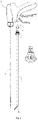
- the present invention reveals a reusable ultrasonic scalpel, comprising a handle assembly and an ultrasonic waveguide 4 extended at its distal end for transmitting ultrasonic mechanical energy.
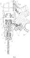
- the handle assembly of the present invention comprises a housing 12, a power touch module set 11 in the housing 12, for the control of ultrasonic energy output, a trigger 16 with its pivot set on the housing 12, and a manual button 17.
- the trigger 16 through the transmission structure 14, 15 passes force to the spring assembly 10.
- the manual button 17 is used to trigger the power touch module 11.
- the housing 12 also includes a reset spring 13 for resetting the transmission structure parts 14 and 15.
- the specific structure and working principle of the handle assembly are approximately the same as those of existing technology, so this will not be repeated here.
- the ultrasonic waveguide 4 outside is equipped with a sheath assembly 1, the sheath assembly 1 is detachably connected to the handle assembly by a quick-connect mechanism.
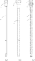
- the sheath assembly 1 comprises an inner sheath assembly and an outer sheath assembly attached to each other.
- the inner sheath assembly comprises an inner sheath 3 and an inner sheath holder 7 fixed at its proximal end
- the outer sheath assembly comprises an outer sheath 2 and outer sheath holder 6 fixed at its proximal end.
- the inner sheath 3 is located between the ultrasonic waveguide 4 and the outer sheath 2, and can move a certain distance along the axis, thus to open or close the active clamp 20, so that the active clamp 20 and the distal end of the waveguide contact or separate.
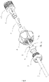
- the sheath assembly 1 and the handle assembly in the present invention have a quick-connect mechanism, which comprises the first quick-connect mechanism and the second quick-connect mechanism.
- the outer sheath holder 6 is fixed in axial direction by means of the first quick-connect mechanism to the tool rotary knob 8 at the distal end of the handle assembly, while the inner sheath holder 7 is fixed in axial direction by the second quick-connect mechanism to the spring seat 9 arranged within the handle assembly as part of the drive mechanism.
- the first quick-connect mechanism comprises the first post 6b mounted on the outer perimeter of the proximal end of the outer sheath holder 6, and the L-slot 8a arranged in the rotary knob 8, and they are mated to each other.
- the second fast-connect mechanism comprises a second post 7a mounted on the outer perimeter of the proximal end of the inner sheath holder 7, and an L-type hook 9a arranged on the spring seat 9, and they are mated to each other.
- the first post 6b in the L-slot 8a axial movement distance is equal to the second post 7a in the L-type hook 9a axial movement distance, so that the two can be mated.
- the axial movement distance of the first post 6b in the L-slot 8a is slightly longer than the axial movement distance of the second post 7a in the L-type hook 9a, so that the first post 6b of the outer sheath holder 6 can slide first Into the L-slot 8a, play as an axial movement guide.
- the inner circumferential surface of the outer sheath holder 6 has a first plane 6c, the outer perimeter of the inner sheath holder 7 has a second plane 7b.
- the outer sheath holder 6 is located over the outer circumference the inner sheath holder 7 and the first plane 6c and the second plane 7b interaction limits the rotation of the inner sheath assembly from the outer sheath assembly, i.e. there will be no relative rotation between the two.
- the tool rotary knob 8 comprises an internal thread, with which a sheath mounting knob 5 with an external thread is connected.
- the proximal end of the sheath mounting knob 5 is facing the outer sheath holder 6 and always exerts a force on it, so that it is fixed between the sheath mounting knob 5 and the tool rotary knob 8.
- the distal end face of the outer sheath holder 6 there is a step plane 6a, which is to touch with the post 5a at the proximal end of the sheath mounting knob 5.
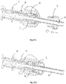
- the first post 6b of the outer sheath holder 6 When installing a disposable sheath assembly, the first post 6b of the outer sheath holder 6 is aligned with the L-slot 8a in the tool rotary knob 8, slide into the tool rotary knob 8 in the direction of the arrow of Fig.14a . Due to The first post 6b on the outer sheath holder 6 has a guiding effect with the L-slot 8a in the tool rotary knob 8, so that the second post 7a on the inner sheath 7 is also aligned with the L-type hook 9a on the spring seat 9.
- the principle of preventing reversal is as follows: when assembling a disposable sheath assembly, because the outer sheath holder 6 has a step plane 6a, when the sheath installation knob 5 rotates in the direction shown in Fig.13 , at the end of the sheath installation knob 5 the post 5a contacts the step plane 6a with a certain force, so that the outer sheath holder 6 is subjected to a certain torque.
- This torque serves two purposes: first, the sheath assembly that is not rotated in place can be rotated to the end of the cross-groove of the L-slot 8a in the tool rotary knob 8, which ensures that the position of the sheath assembly is precise. Second, this torque prevents from loose or reversal.
- the step plane 6a can also be a sloped end face with a smooth transition, that is, it only needs a height difference at the distal end surface of the outer sheath holder 6.
- the number of the first post 6b and the second post 7a is not specified.
- Technical personal in the art should know that 1, 2, or more are possible.
- the inner sheath 3 and the inner sheath holder 7, the outer sheath 2 and the outer sheath holder 6 are both formed by the mold injection molding process or glue bonding (Insert molding) for making the connecting structure.
- the mold injection molding process or glue bonding glue bonding
- This invention uses the mold injection molding process or glue bonding, not only can reduce the product scrap rate, but also can make more complex structure to achieve required functions.
- the handle assembly and the ultrasonic waveguide 4 of the present invention are made of high temperature-resistant materials (high-temperature plastic: PPA, PEI, etc.; high-temperature metal: titanium alloy, stainless steel, etc.) and can be cleansed and undergoing high-temperature steam sterilization.
- high temperature-resistant materials high-temperature plastic: PPA, PEI, etc.; high-temperature metal: titanium alloy, stainless steel, etc.
- the invention provides a convenient design for disassembling and assembling, and the user can disassemble and assemble the sheath assembly and the reusable parts in a very short time and easy for hospital use.
Landscapes
- Health & Medical Sciences (AREA)
- Life Sciences & Earth Sciences (AREA)
- Surgery (AREA)
- Engineering & Computer Science (AREA)
- Medical Informatics (AREA)
- Biomedical Technology (AREA)
- Heart & Thoracic Surgery (AREA)
- Nuclear Medicine, Radiotherapy & Molecular Imaging (AREA)
- Molecular Biology (AREA)
- Animal Behavior & Ethology (AREA)
- General Health & Medical Sciences (AREA)
- Public Health (AREA)
- Veterinary Medicine (AREA)
- Dentistry (AREA)
- Mechanical Engineering (AREA)
- Orthopedic Medicine & Surgery (AREA)
- Ophthalmology & Optometry (AREA)
- Surgical Instruments (AREA)
Applications Claiming Priority (2)
| Application Number | Priority Date | Filing Date | Title |
|---|---|---|---|
| CN201910752035.3A CN110448357B (zh) | 2019-08-15 | 2019-08-15 | 可重复利用的超声波手术刀 |
| PCT/CN2020/084408 WO2021027302A1 (fr) | 2019-08-15 | 2020-04-13 | Scalpel à ultrasons réutilisable |
Publications (3)
| Publication Number | Publication Date |
|---|---|
| EP4014899A1 true EP4014899A1 (fr) | 2022-06-22 |
| EP4014899A4 EP4014899A4 (fr) | 2023-09-06 |
| EP4014899B1 EP4014899B1 (fr) | 2024-11-20 |
Family
ID=68486606
Family Applications (1)
| Application Number | Title | Priority Date | Filing Date |
|---|---|---|---|
| EP20852980.0A Active EP4014899B1 (fr) | 2019-08-15 | 2020-04-13 | Scalpel à ultrasons réutilisable |
Country Status (7)
| Country | Link |
|---|---|
| US (1) | US12285187B2 (fr) |
| EP (1) | EP4014899B1 (fr) |
| JP (1) | JP7232941B2 (fr) |
| KR (1) | KR102682648B1 (fr) |
| CN (1) | CN110448357B (fr) |
| BR (1) | BR112022001682A2 (fr) |
| WO (1) | WO2021027302A1 (fr) |
Families Citing this family (15)
| Publication number | Priority date | Publication date | Assignee | Title |
|---|---|---|---|---|
| USD847990S1 (en) * | 2016-08-16 | 2019-05-07 | Ethicon Llc | Surgical instrument |
| CN107928752B (zh) * | 2017-12-23 | 2024-02-27 | 博思研生物技术(苏州)有限公司 | 带一次性使用刀头的外科手术超声刀 |
| CN110448357B (zh) | 2019-08-15 | 2024-01-09 | 以诺康医疗科技(苏州)有限公司 | 可重复利用的超声波手术刀 |
| CN113057715B (zh) * | 2020-01-02 | 2023-04-21 | 上海逸思医疗科技股份有限公司 | 一种可拆装器械 |
| CN112515738B (zh) * | 2020-11-12 | 2023-06-13 | 嘉善飞阔医疗科技有限公司 | 一种可稳定重复使用的超声波手术刀 |
| CN112515739A (zh) * | 2020-11-12 | 2021-03-19 | 嘉善飞阔医疗科技有限公司 | 一种可提高使用寿命的超声波手术刀 |
| CN115211934A (zh) | 2021-04-16 | 2022-10-21 | 上海逸思医疗科技股份有限公司 | 一种超声外科手术器械及加工组装方法 |
| CN113229891B (zh) * | 2021-05-21 | 2024-03-12 | 以诺康医疗科技(苏州)有限公司 | 多功能手术器械 |
| CN115005932B (zh) * | 2022-04-26 | 2025-09-30 | 北京安和加利尔科技有限公司 | 一种微创手术使用的可更换刀杆的超声刀 |
| CN115054373B (zh) * | 2022-06-02 | 2023-03-21 | 以诺康医疗科技(苏州)有限公司 | 可拆卸式手术机器人末端执行装置及手术机器人 |
| CN115153680B (zh) * | 2022-07-15 | 2023-06-02 | 经纬医疗器材制造(深圳)有限公司 | 一种适于手术器械的连接装置及手术器械 |
| CN115024768B (zh) * | 2022-08-09 | 2022-11-04 | 生一科技(北京)有限公司 | 微创手术器械组件及微创手术器械 |
| CN116138846B (zh) * | 2022-09-26 | 2025-08-26 | 杭州康基唯精医疗机器人有限公司 | 适用于超声刀的刀杆组件 |
| CN115530929B (zh) * | 2022-10-13 | 2024-04-16 | 以诺康医疗科技(苏州)有限公司 | 一种精细手术器械 |
| CN222693484U (zh) * | 2024-03-29 | 2025-04-01 | 北京水木天蓬医疗设备有限公司 | 外科器械 |
Family Cites Families (23)
| Publication number | Priority date | Publication date | Assignee | Title |
|---|---|---|---|---|
| US5346502A (en) * | 1993-04-15 | 1994-09-13 | Ultracision, Inc. | Laparoscopic ultrasonic surgical instrument and methods for manufacturing the instruments |
| US8114104B2 (en) | 2006-06-01 | 2012-02-14 | Ethicon Endo-Surgery, Inc. | Mechanism for assembly of ultrasonic instrument |
| US8142461B2 (en) | 2007-03-22 | 2012-03-27 | Ethicon Endo-Surgery, Inc. | Surgical instruments |
| US10207045B2 (en) * | 2008-06-26 | 2019-02-19 | Surgical Design Corporation | Surgical handpiece with disposable concentric lumen work tip |
| US10166317B2 (en) * | 2008-06-26 | 2019-01-01 | Surgical Design Corporation | Surgical hand piece with dual lumen work tip for use with infusion cannula |
| US8951272B2 (en) * | 2010-02-11 | 2015-02-10 | Ethicon Endo-Surgery, Inc. | Seal arrangements for ultrasonically powered surgical instruments |
| CN201811496U (zh) | 2010-09-08 | 2011-04-27 | 唐际秋 | 储热式多级污水废热回收热泵系统 |
| CA2816875A1 (fr) | 2010-11-05 | 2012-05-10 | Ethicon Endo-Surgery, Inc. | Instrument chirurgical pourvu d'un effecteur d'extremite modulaire |
| US9510895B2 (en) * | 2010-11-05 | 2016-12-06 | Ethicon Endo-Surgery, Llc | Surgical instrument with modular shaft and end effector |
| CN104783868B (zh) * | 2014-01-20 | 2018-08-10 | 北京安和加利尔科技有限公司 | 一种具有可换刀头的超声手术刀刀杆 |
| US10327797B2 (en) * | 2015-10-16 | 2019-06-25 | Ethicon Llc | Ultrasonic surgical instrument with removable shaft assembly portion |
| US11464534B2 (en) * | 2015-12-08 | 2022-10-11 | Reach Surgical, Inc. | Ultrasonic surgical instrument |
| TWI721278B (zh) | 2017-06-15 | 2021-03-11 | 大陸商天津瑞奇外科器械股份有限公司 | 超聲外科手術器械 |
| US10820920B2 (en) | 2017-07-05 | 2020-11-03 | Ethicon Llc | Reusable ultrasonic medical devices and methods of their use |
| CN107280735B (zh) | 2017-07-21 | 2020-08-04 | 上海逸思医疗科技有限公司 | 可重复使用的超声手术器械 |
| US11039955B2 (en) * | 2017-11-22 | 2021-06-22 | Surgical Design Corporation | Low-cost disposable ultrasonic surgical handpiece |
| CN108354652A (zh) * | 2018-02-08 | 2018-08-03 | 南昌元合泽众科技有限公司 | 一种可重复使用的超声手术刀 |
| CN109009330B (zh) * | 2018-08-02 | 2023-09-29 | 嘉善飞阔医疗科技有限公司 | 超声波手术刀及超声波手术刀系统 |
| US11051828B2 (en) * | 2018-08-13 | 2021-07-06 | Covidien Lp | Rotation knob assemblies and surgical instruments including same |
| CN209153877U (zh) * | 2018-09-25 | 2019-07-26 | 嘉善飞阔医疗科技有限公司 | 可重复使用的超声波手术刀 |
| CN108969058B (zh) * | 2018-09-25 | 2023-10-13 | 嘉善飞阔医疗科技有限公司 | 可重复使用的超声波手术刀 |
| CN110448357B (zh) * | 2019-08-15 | 2024-01-09 | 以诺康医疗科技(苏州)有限公司 | 可重复利用的超声波手术刀 |
| CN211609975U (zh) * | 2019-08-15 | 2020-10-02 | 以诺康医疗科技(苏州)有限公司 | 可重复利用的超声波手术刀 |
-
2019
- 2019-08-15 CN CN201910752035.3A patent/CN110448357B/zh active Active
-
2020
- 2020-04-13 EP EP20852980.0A patent/EP4014899B1/fr active Active
- 2020-04-13 BR BR112022001682A patent/BR112022001682A2/pt active Search and Examination
- 2020-04-13 JP JP2021576457A patent/JP7232941B2/ja active Active
- 2020-04-13 KR KR1020227002158A patent/KR102682648B1/ko active Active
- 2020-04-13 US US17/635,195 patent/US12285187B2/en active Active
- 2020-04-13 WO PCT/CN2020/084408 patent/WO2021027302A1/fr not_active Ceased
Also Published As
| Publication number | Publication date |
|---|---|
| US20220287736A1 (en) | 2022-09-15 |
| EP4014899B1 (fr) | 2024-11-20 |
| JP2022543339A (ja) | 2022-10-12 |
| EP4014899A4 (fr) | 2023-09-06 |
| CN110448357A (zh) | 2019-11-15 |
| KR102682648B1 (ko) | 2024-07-05 |
| US12285187B2 (en) | 2025-04-29 |
| WO2021027302A1 (fr) | 2021-02-18 |
| JP7232941B2 (ja) | 2023-03-03 |
| BR112022001682A2 (pt) | 2022-05-24 |
| KR20220024828A (ko) | 2022-03-03 |
| CN110448357B (zh) | 2024-01-09 |
Similar Documents
| Publication | Publication Date | Title |
|---|---|---|
| EP4014899B1 (fr) | Scalpel à ultrasons réutilisable | |
| JP5872489B2 (ja) | 回転切断用具を備える、超音波駆動の外科用器具 | |
| JP5813668B2 (ja) | 超音波駆動の外科用器具のための封止構成 | |
| JP5908412B2 (ja) | 回転可能なブレード及び中空のシース構成を有する超音波外科用器具 | |
| US12295610B2 (en) | Ultrasonic surgical instrument | |
| US9192428B2 (en) | Surgical instrument with modular clamp pad | |
| EP3747378B1 (fr) | Instrument chirurgical à ultrasons comprenant une partie ensemble tige amovible | |
| CN102843980B (zh) | 超声外科器械的旋转切割工具构造 | |
| EP2533710B1 (fr) | Instrument chirurgical double effet pour couper et coaguler un tissu | |
| EP2635220B1 (fr) | Instrument chirurgical pourvu d'un effecteur d'extrémité modulaire | |
| CN211609975U (zh) | 可重复利用的超声波手术刀 | |
| BR112018007763B1 (pt) | Kit | |
| CN103108596A (zh) | 使用具有旋转切割工具的超声动力外科器械的方法 | |
| AU2011323287A1 (en) | Surgical instrument with modular clamp pad | |
| US12076007B2 (en) | Reusable stapler with detachable adapter | |
| CN210494159U (zh) | 一种可拆卸适配器的重复使用吻合器 | |
| CN216365187U (zh) | 一种超声外科手术器械 | |
| CN115211934A (zh) | 一种超声外科手术器械及加工组装方法 | |
| CN217447985U (zh) | 一种电切内窥镜的锁紧结构 | |
| WO2023139481A1 (fr) | Instrument chirurgical à ultrasons |
Legal Events
| Date | Code | Title | Description |
|---|---|---|---|
| STAA | Information on the status of an ep patent application or granted ep patent |
Free format text: STATUS: THE INTERNATIONAL PUBLICATION HAS BEEN MADE |
|
| PUAI | Public reference made under article 153(3) epc to a published international application that has entered the european phase |
Free format text: ORIGINAL CODE: 0009012 |
|
| STAA | Information on the status of an ep patent application or granted ep patent |
Free format text: STATUS: REQUEST FOR EXAMINATION WAS MADE |
|
| 17P | Request for examination filed |
Effective date: 20220315 |
|
| AK | Designated contracting states |
Kind code of ref document: A1 Designated state(s): AL AT BE BG CH CY CZ DE DK EE ES FI FR GB GR HR HU IE IS IT LI LT LU LV MC MK MT NL NO PL PT RO RS SE SI SK SM TR |
|
| DAV | Request for validation of the european patent (deleted) | ||
| DAX | Request for extension of the european patent (deleted) | ||
| A4 | Supplementary search report drawn up and despatched |
Effective date: 20230808 |
|
| RIC1 | Information provided on ipc code assigned before grant |
Ipc: A61B 17/32 20060101AFI20230802BHEP |
|
| GRAP | Despatch of communication of intention to grant a patent |
Free format text: ORIGINAL CODE: EPIDOSNIGR1 |
|
| STAA | Information on the status of an ep patent application or granted ep patent |
Free format text: STATUS: GRANT OF PATENT IS INTENDED |
|
| INTG | Intention to grant announced |
Effective date: 20240626 |
|
| P01 | Opt-out of the competence of the unified patent court (upc) registered |
Free format text: CASE NUMBER: APP_48584/2024 Effective date: 20240826 |
|
| GRAS | Grant fee paid |
Free format text: ORIGINAL CODE: EPIDOSNIGR3 |
|
| GRAA | (expected) grant |
Free format text: ORIGINAL CODE: 0009210 |
|
| STAA | Information on the status of an ep patent application or granted ep patent |
Free format text: STATUS: THE PATENT HAS BEEN GRANTED |
|
| AK | Designated contracting states |
Kind code of ref document: B1 Designated state(s): AL AT BE BG CH CY CZ DE DK EE ES FI FR GB GR HR HU IE IS IT LI LT LU LV MC MK MT NL NO PL PT RO RS SE SI SK SM TR |
|
| REG | Reference to a national code |
Ref country code: GB Ref legal event code: FG4D |
|
| REG | Reference to a national code |
Ref country code: CH Ref legal event code: EP |
|
| REG | Reference to a national code |
Ref country code: DE Ref legal event code: R096 Ref document number: 602020041823 Country of ref document: DE |
|
| REG | Reference to a national code |
Ref country code: IE Ref legal event code: FG4D |
|
| REG | Reference to a national code |
Ref country code: LT Ref legal event code: MG9D |
|
| REG | Reference to a national code |
Ref country code: NL Ref legal event code: MP Effective date: 20241120 |
|
| PG25 | Lapsed in a contracting state [announced via postgrant information from national office to epo] |
Ref country code: PT Free format text: LAPSE BECAUSE OF FAILURE TO SUBMIT A TRANSLATION OF THE DESCRIPTION OR TO PAY THE FEE WITHIN THE PRESCRIBED TIME-LIMIT Effective date: 20250320 Ref country code: HR Free format text: LAPSE BECAUSE OF FAILURE TO SUBMIT A TRANSLATION OF THE DESCRIPTION OR TO PAY THE FEE WITHIN THE PRESCRIBED TIME-LIMIT Effective date: 20241120 Ref country code: IS Free format text: LAPSE BECAUSE OF FAILURE TO SUBMIT A TRANSLATION OF THE DESCRIPTION OR TO PAY THE FEE WITHIN THE PRESCRIBED TIME-LIMIT Effective date: 20250320 |
|
| PG25 | Lapsed in a contracting state [announced via postgrant information from national office to epo] |
Ref country code: NL Free format text: LAPSE BECAUSE OF FAILURE TO SUBMIT A TRANSLATION OF THE DESCRIPTION OR TO PAY THE FEE WITHIN THE PRESCRIBED TIME-LIMIT Effective date: 20241120 Ref country code: FI Free format text: LAPSE BECAUSE OF FAILURE TO SUBMIT A TRANSLATION OF THE DESCRIPTION OR TO PAY THE FEE WITHIN THE PRESCRIBED TIME-LIMIT Effective date: 20241120 |
|
| REG | Reference to a national code |
Ref country code: AT Ref legal event code: MK05 Ref document number: 1742846 Country of ref document: AT Kind code of ref document: T Effective date: 20241120 |
|
| PG25 | Lapsed in a contracting state [announced via postgrant information from national office to epo] |
Ref country code: BG Free format text: LAPSE BECAUSE OF FAILURE TO SUBMIT A TRANSLATION OF THE DESCRIPTION OR TO PAY THE FEE WITHIN THE PRESCRIBED TIME-LIMIT Effective date: 20241120 |
|
| PG25 | Lapsed in a contracting state [announced via postgrant information from national office to epo] |
Ref country code: ES Free format text: LAPSE BECAUSE OF FAILURE TO SUBMIT A TRANSLATION OF THE DESCRIPTION OR TO PAY THE FEE WITHIN THE PRESCRIBED TIME-LIMIT Effective date: 20241120 |
|
| PG25 | Lapsed in a contracting state [announced via postgrant information from national office to epo] |
Ref country code: NO Free format text: LAPSE BECAUSE OF FAILURE TO SUBMIT A TRANSLATION OF THE DESCRIPTION OR TO PAY THE FEE WITHIN THE PRESCRIBED TIME-LIMIT Effective date: 20250220 |
|
| PG25 | Lapsed in a contracting state [announced via postgrant information from national office to epo] |
Ref country code: LV Free format text: LAPSE BECAUSE OF FAILURE TO SUBMIT A TRANSLATION OF THE DESCRIPTION OR TO PAY THE FEE WITHIN THE PRESCRIBED TIME-LIMIT Effective date: 20241120 Ref country code: GR Free format text: LAPSE BECAUSE OF FAILURE TO SUBMIT A TRANSLATION OF THE DESCRIPTION OR TO PAY THE FEE WITHIN THE PRESCRIBED TIME-LIMIT Effective date: 20250221 Ref country code: AT Free format text: LAPSE BECAUSE OF FAILURE TO SUBMIT A TRANSLATION OF THE DESCRIPTION OR TO PAY THE FEE WITHIN THE PRESCRIBED TIME-LIMIT Effective date: 20241120 |
|
| PG25 | Lapsed in a contracting state [announced via postgrant information from national office to epo] |
Ref country code: PL Free format text: LAPSE BECAUSE OF FAILURE TO SUBMIT A TRANSLATION OF THE DESCRIPTION OR TO PAY THE FEE WITHIN THE PRESCRIBED TIME-LIMIT Effective date: 20241120 |
|
| PG25 | Lapsed in a contracting state [announced via postgrant information from national office to epo] |
Ref country code: RS Free format text: LAPSE BECAUSE OF FAILURE TO SUBMIT A TRANSLATION OF THE DESCRIPTION OR TO PAY THE FEE WITHIN THE PRESCRIBED TIME-LIMIT Effective date: 20250220 |
|
| PG25 | Lapsed in a contracting state [announced via postgrant information from national office to epo] |
Ref country code: SM Free format text: LAPSE BECAUSE OF FAILURE TO SUBMIT A TRANSLATION OF THE DESCRIPTION OR TO PAY THE FEE WITHIN THE PRESCRIBED TIME-LIMIT Effective date: 20241120 |
|
| PGFP | Annual fee paid to national office [announced via postgrant information from national office to epo] |
Ref country code: DE Payment date: 20250411 Year of fee payment: 6 |
|
| PG25 | Lapsed in a contracting state [announced via postgrant information from national office to epo] |
Ref country code: DK Free format text: LAPSE BECAUSE OF FAILURE TO SUBMIT A TRANSLATION OF THE DESCRIPTION OR TO PAY THE FEE WITHIN THE PRESCRIBED TIME-LIMIT Effective date: 20241120 |
|
| PG25 | Lapsed in a contracting state [announced via postgrant information from national office to epo] |
Ref country code: EE Free format text: LAPSE BECAUSE OF FAILURE TO SUBMIT A TRANSLATION OF THE DESCRIPTION OR TO PAY THE FEE WITHIN THE PRESCRIBED TIME-LIMIT Effective date: 20241120 |
|
| PG25 | Lapsed in a contracting state [announced via postgrant information from national office to epo] |
Ref country code: RO Free format text: LAPSE BECAUSE OF FAILURE TO SUBMIT A TRANSLATION OF THE DESCRIPTION OR TO PAY THE FEE WITHIN THE PRESCRIBED TIME-LIMIT Effective date: 20241120 |
|
| PG25 | Lapsed in a contracting state [announced via postgrant information from national office to epo] |
Ref country code: SK Free format text: LAPSE BECAUSE OF FAILURE TO SUBMIT A TRANSLATION OF THE DESCRIPTION OR TO PAY THE FEE WITHIN THE PRESCRIBED TIME-LIMIT Effective date: 20241120 |
|
| PG25 | Lapsed in a contracting state [announced via postgrant information from national office to epo] |
Ref country code: CZ Free format text: LAPSE BECAUSE OF FAILURE TO SUBMIT A TRANSLATION OF THE DESCRIPTION OR TO PAY THE FEE WITHIN THE PRESCRIBED TIME-LIMIT Effective date: 20241120 |
|
| PG25 | Lapsed in a contracting state [announced via postgrant information from national office to epo] |
Ref country code: IT Free format text: LAPSE BECAUSE OF FAILURE TO SUBMIT A TRANSLATION OF THE DESCRIPTION OR TO PAY THE FEE WITHIN THE PRESCRIBED TIME-LIMIT Effective date: 20241120 |
|
| REG | Reference to a national code |
Ref country code: DE Ref legal event code: R097 Ref document number: 602020041823 Country of ref document: DE |
|
| PG25 | Lapsed in a contracting state [announced via postgrant information from national office to epo] |
Ref country code: SE Free format text: LAPSE BECAUSE OF FAILURE TO SUBMIT A TRANSLATION OF THE DESCRIPTION OR TO PAY THE FEE WITHIN THE PRESCRIBED TIME-LIMIT Effective date: 20241120 |
|
| PLBE | No opposition filed within time limit |
Free format text: ORIGINAL CODE: 0009261 |
|
| STAA | Information on the status of an ep patent application or granted ep patent |
Free format text: STATUS: NO OPPOSITION FILED WITHIN TIME LIMIT |
|
| 26N | No opposition filed |
Effective date: 20250821 |
|
| REG | Reference to a national code |
Ref country code: CH Ref legal event code: H13 Free format text: ST27 STATUS EVENT CODE: U-0-0-H10-H13 (AS PROVIDED BY THE NATIONAL OFFICE) Effective date: 20251125 |
|
| PG25 | Lapsed in a contracting state [announced via postgrant information from national office to epo] |
Ref country code: LU Free format text: LAPSE BECAUSE OF NON-PAYMENT OF DUE FEES Effective date: 20250413 |
|
| PG25 | Lapsed in a contracting state [announced via postgrant information from national office to epo] |
Ref country code: MC Free format text: LAPSE BECAUSE OF FAILURE TO SUBMIT A TRANSLATION OF THE DESCRIPTION OR TO PAY THE FEE WITHIN THE PRESCRIBED TIME-LIMIT Effective date: 20241120 |
|
| GBPC | Gb: european patent ceased through non-payment of renewal fee |
Effective date: 20250413 |
|
| REG | Reference to a national code |
Ref country code: BE Ref legal event code: MM Effective date: 20250430 |
|
| PG25 | Lapsed in a contracting state [announced via postgrant information from national office to epo] |
Ref country code: GB Free format text: LAPSE BECAUSE OF NON-PAYMENT OF DUE FEES Effective date: 20250413 |
|
| PG25 | Lapsed in a contracting state [announced via postgrant information from national office to epo] |
Ref country code: FR Free format text: LAPSE BECAUSE OF NON-PAYMENT OF DUE FEES Effective date: 20250430 |
|
| PG25 | Lapsed in a contracting state [announced via postgrant information from national office to epo] |
Ref country code: BE Free format text: LAPSE BECAUSE OF NON-PAYMENT OF DUE FEES Effective date: 20250430 |
|
| PG25 | Lapsed in a contracting state [announced via postgrant information from national office to epo] |
Ref country code: CH Free format text: LAPSE BECAUSE OF NON-PAYMENT OF DUE FEES Effective date: 20250430 |
|
| PG25 | Lapsed in a contracting state [announced via postgrant information from national office to epo] |
Ref country code: IE Free format text: LAPSE BECAUSE OF NON-PAYMENT OF DUE FEES Effective date: 20250413 |