EP4015067A1 - Filtre à particules catalytiquement actif à efficacité de filtration élevée - Google Patents
Filtre à particules catalytiquement actif à efficacité de filtration élevée Download PDFInfo
- Publication number
- EP4015067A1 EP4015067A1 EP20214160.2A EP20214160A EP4015067A1 EP 4015067 A1 EP4015067 A1 EP 4015067A1 EP 20214160 A EP20214160 A EP 20214160A EP 4015067 A1 EP4015067 A1 EP 4015067A1
- Authority
- EP
- European Patent Office
- Prior art keywords
- coating
- wall
- flow filter
- oxide
- filter according
- Prior art date
- Legal status (The legal status is an assumption and is not a legal conclusion. Google has not performed a legal analysis and makes no representation as to the accuracy of the status listed.)
- Pending
Links
Images



Classifications
-
- B—PERFORMING OPERATIONS; TRANSPORTING
- B01—PHYSICAL OR CHEMICAL PROCESSES OR APPARATUS IN GENERAL
- B01D—SEPARATION
- B01D53/00—Separation of gases or vapours; Recovering vapours of volatile solvents from gases; Chemical or biological purification of waste gases, e.g. engine exhaust gases, smoke, fumes, flue gases, aerosols
- B01D53/34—Chemical or biological purification of waste gases
- B01D53/92—Chemical or biological purification of waste gases of engine exhaust gases
- B01D53/94—Chemical or biological purification of waste gases of engine exhaust gases by catalytic processes
- B01D53/9445—Simultaneously removing carbon monoxide, hydrocarbons or nitrogen oxides making use of three-way catalysts [TWC] or four-way-catalysts [FWC]
- B01D53/945—Simultaneously removing carbon monoxide, hydrocarbons or nitrogen oxides making use of three-way catalysts [TWC] or four-way-catalysts [FWC] characterised by a specific catalyst
-
- B—PERFORMING OPERATIONS; TRANSPORTING
- B01—PHYSICAL OR CHEMICAL PROCESSES OR APPARATUS IN GENERAL
- B01J—CHEMICAL OR PHYSICAL PROCESSES, e.g. CATALYSIS OR COLLOID CHEMISTRY; THEIR RELEVANT APPARATUS
- B01J21/00—Catalysts comprising the elements, oxides, or hydroxides of magnesium, boron, aluminium, carbon, silicon, titanium, zirconium, or hafnium
- B01J21/06—Silicon, titanium, zirconium or hafnium; Oxides or hydroxides thereof
- B01J21/066—Zirconium or hafnium; Oxides or hydroxides thereof
-
- B—PERFORMING OPERATIONS; TRANSPORTING
- B01—PHYSICAL OR CHEMICAL PROCESSES OR APPARATUS IN GENERAL
- B01J—CHEMICAL OR PHYSICAL PROCESSES, e.g. CATALYSIS OR COLLOID CHEMISTRY; THEIR RELEVANT APPARATUS
- B01J23/00—Catalysts comprising metals or metal oxides or hydroxides, not provided for in group B01J21/00
- B01J23/38—Catalysts comprising metals or metal oxides or hydroxides, not provided for in group B01J21/00 of noble metals
- B01J23/54—Catalysts comprising metals or metal oxides or hydroxides, not provided for in group B01J21/00 of noble metals combined with metals, oxides or hydroxides provided for in groups B01J23/02 - B01J23/36
- B01J23/56—Platinum group metals
- B01J23/63—Platinum group metals with rare earths or actinides
-
- B—PERFORMING OPERATIONS; TRANSPORTING
- B01—PHYSICAL OR CHEMICAL PROCESSES OR APPARATUS IN GENERAL
- B01J—CHEMICAL OR PHYSICAL PROCESSES, e.g. CATALYSIS OR COLLOID CHEMISTRY; THEIR RELEVANT APPARATUS
- B01J35/00—Catalysts, in general, characterised by their form or physical properties
- B01J35/50—Catalysts, in general, characterised by their form or physical properties characterised by their shape or configuration
- B01J35/56—Foraminous structures having flow-through passages or channels, e.g. grids or three-dimensional [3D] monoliths
-
- F—MECHANICAL ENGINEERING; LIGHTING; HEATING; WEAPONS; BLASTING
- F01—MACHINES OR ENGINES IN GENERAL; ENGINE PLANTS IN GENERAL; STEAM ENGINES
- F01N—GAS-FLOW SILENCERS OR EXHAUST APPARATUS FOR MACHINES OR ENGINES IN GENERAL; GAS-FLOW SILENCERS OR EXHAUST APPARATUS FOR INTERNAL-COMBUSTION ENGINES
- F01N3/00—Exhaust or silencing apparatus having means for purifying, rendering innocuous, or otherwise treating exhaust
- F01N3/02—Exhaust or silencing apparatus having means for purifying, rendering innocuous, or otherwise treating exhaust for cooling, or for removing solid constituents of, exhaust
- F01N3/021—Exhaust or silencing apparatus having means for purifying, rendering innocuous, or otherwise treating exhaust for cooling, or for removing solid constituents of, exhaust by means of filters
-
- F—MECHANICAL ENGINEERING; LIGHTING; HEATING; WEAPONS; BLASTING
- F01—MACHINES OR ENGINES IN GENERAL; ENGINE PLANTS IN GENERAL; STEAM ENGINES
- F01N—GAS-FLOW SILENCERS OR EXHAUST APPARATUS FOR MACHINES OR ENGINES IN GENERAL; GAS-FLOW SILENCERS OR EXHAUST APPARATUS FOR INTERNAL-COMBUSTION ENGINES
- F01N3/00—Exhaust or silencing apparatus having means for purifying, rendering innocuous, or otherwise treating exhaust
- F01N3/02—Exhaust or silencing apparatus having means for purifying, rendering innocuous, or otherwise treating exhaust for cooling, or for removing solid constituents of, exhaust
- F01N3/021—Exhaust or silencing apparatus having means for purifying, rendering innocuous, or otherwise treating exhaust for cooling, or for removing solid constituents of, exhaust by means of filters
- F01N3/033—Exhaust or silencing apparatus having means for purifying, rendering innocuous, or otherwise treating exhaust for cooling, or for removing solid constituents of, exhaust by means of filters in combination with other devices
- F01N3/035—Exhaust or silencing apparatus having means for purifying, rendering innocuous, or otherwise treating exhaust for cooling, or for removing solid constituents of, exhaust by means of filters in combination with other devices with catalytic reactors
-
- F—MECHANICAL ENGINEERING; LIGHTING; HEATING; WEAPONS; BLASTING
- F01—MACHINES OR ENGINES IN GENERAL; ENGINE PLANTS IN GENERAL; STEAM ENGINES
- F01N—GAS-FLOW SILENCERS OR EXHAUST APPARATUS FOR MACHINES OR ENGINES IN GENERAL; GAS-FLOW SILENCERS OR EXHAUST APPARATUS FOR INTERNAL-COMBUSTION ENGINES
- F01N3/00—Exhaust or silencing apparatus having means for purifying, rendering innocuous, or otherwise treating exhaust
- F01N3/08—Exhaust or silencing apparatus having means for purifying, rendering innocuous, or otherwise treating exhaust for rendering innocuous
- F01N3/10—Exhaust or silencing apparatus having means for purifying, rendering innocuous, or otherwise treating exhaust for rendering innocuous by thermal or catalytic conversion of noxious components of exhaust
- F01N3/24—Exhaust or silencing apparatus having means for purifying, rendering innocuous, or otherwise treating exhaust for rendering innocuous by thermal or catalytic conversion of noxious components of exhaust characterised by constructional aspects of converting apparatus
- F01N3/28—Construction of catalytic reactors
- F01N3/2803—Construction of catalytic reactors characterised by structure, by material or by manufacturing of catalyst support
-
- B—PERFORMING OPERATIONS; TRANSPORTING
- B01—PHYSICAL OR CHEMICAL PROCESSES OR APPARATUS IN GENERAL
- B01D—SEPARATION
- B01D2255/00—Catalysts
- B01D2255/10—Noble metals or compounds thereof
- B01D2255/102—Platinum group metals
- B01D2255/1021—Platinum
-
- B—PERFORMING OPERATIONS; TRANSPORTING
- B01—PHYSICAL OR CHEMICAL PROCESSES OR APPARATUS IN GENERAL
- B01D—SEPARATION
- B01D2255/00—Catalysts
- B01D2255/10—Noble metals or compounds thereof
- B01D2255/102—Platinum group metals
- B01D2255/1023—Palladium
-
- B—PERFORMING OPERATIONS; TRANSPORTING
- B01—PHYSICAL OR CHEMICAL PROCESSES OR APPARATUS IN GENERAL
- B01D—SEPARATION
- B01D2255/00—Catalysts
- B01D2255/10—Noble metals or compounds thereof
- B01D2255/102—Platinum group metals
- B01D2255/1025—Rhodium
-
- B—PERFORMING OPERATIONS; TRANSPORTING
- B01—PHYSICAL OR CHEMICAL PROCESSES OR APPARATUS IN GENERAL
- B01D—SEPARATION
- B01D2255/00—Catalysts
- B01D2255/40—Mixed oxides
- B01D2255/407—Zr-Ce mixed oxides
-
- B—PERFORMING OPERATIONS; TRANSPORTING
- B01—PHYSICAL OR CHEMICAL PROCESSES OR APPARATUS IN GENERAL
- B01D—SEPARATION
- B01D2255/00—Catalysts
- B01D2255/90—Physical characteristics of catalysts
- B01D2255/915—Catalyst supported on particulate filters
- B01D2255/9155—Wall flow filters
-
- B—PERFORMING OPERATIONS; TRANSPORTING
- B01—PHYSICAL OR CHEMICAL PROCESSES OR APPARATUS IN GENERAL
- B01D—SEPARATION
- B01D2258/00—Sources of waste gases
- B01D2258/01—Engine exhaust gases
- B01D2258/014—Stoichiometric gasoline engines
-
- F—MECHANICAL ENGINEERING; LIGHTING; HEATING; WEAPONS; BLASTING
- F01—MACHINES OR ENGINES IN GENERAL; ENGINE PLANTS IN GENERAL; STEAM ENGINES
- F01N—GAS-FLOW SILENCERS OR EXHAUST APPARATUS FOR MACHINES OR ENGINES IN GENERAL; GAS-FLOW SILENCERS OR EXHAUST APPARATUS FOR INTERNAL-COMBUSTION ENGINES
- F01N2510/00—Surface coverings
- F01N2510/06—Surface coverings for exhaust purification, e.g. catalytic reaction
-
- F—MECHANICAL ENGINEERING; LIGHTING; HEATING; WEAPONS; BLASTING
- F01—MACHINES OR ENGINES IN GENERAL; ENGINE PLANTS IN GENERAL; STEAM ENGINES
- F01N—GAS-FLOW SILENCERS OR EXHAUST APPARATUS FOR MACHINES OR ENGINES IN GENERAL; GAS-FLOW SILENCERS OR EXHAUST APPARATUS FOR INTERNAL-COMBUSTION ENGINES
- F01N2510/00—Surface coverings
- F01N2510/06—Surface coverings for exhaust purification, e.g. catalytic reaction
- F01N2510/068—Surface coverings for exhaust purification, e.g. catalytic reaction characterised by the distribution of the catalytic coatings
-
- F—MECHANICAL ENGINEERING; LIGHTING; HEATING; WEAPONS; BLASTING
- F01—MACHINES OR ENGINES IN GENERAL; ENGINE PLANTS IN GENERAL; STEAM ENGINES
- F01N—GAS-FLOW SILENCERS OR EXHAUST APPARATUS FOR MACHINES OR ENGINES IN GENERAL; GAS-FLOW SILENCERS OR EXHAUST APPARATUS FOR INTERNAL-COMBUSTION ENGINES
- F01N2510/00—Surface coverings
- F01N2510/06—Surface coverings for exhaust purification, e.g. catalytic reaction
- F01N2510/068—Surface coverings for exhaust purification, e.g. catalytic reaction characterised by the distribution of the catalytic coatings
- F01N2510/0682—Surface coverings for exhaust purification, e.g. catalytic reaction characterised by the distribution of the catalytic coatings having a discontinuous, uneven or partially overlapping coating of catalytic material, e.g. higher amount of material upstream than downstream or vice versa
-
- F—MECHANICAL ENGINEERING; LIGHTING; HEATING; WEAPONS; BLASTING
- F01—MACHINES OR ENGINES IN GENERAL; ENGINE PLANTS IN GENERAL; STEAM ENGINES
- F01N—GAS-FLOW SILENCERS OR EXHAUST APPARATUS FOR MACHINES OR ENGINES IN GENERAL; GAS-FLOW SILENCERS OR EXHAUST APPARATUS FOR INTERNAL-COMBUSTION ENGINES
- F01N2510/00—Surface coverings
- F01N2510/06—Surface coverings for exhaust purification, e.g. catalytic reaction
- F01N2510/068—Surface coverings for exhaust purification, e.g. catalytic reaction characterised by the distribution of the catalytic coatings
- F01N2510/0684—Surface coverings for exhaust purification, e.g. catalytic reaction characterised by the distribution of the catalytic coatings having more than one coating layer, e.g. multi-layered coatings
-
- Y—GENERAL TAGGING OF NEW TECHNOLOGICAL DEVELOPMENTS; GENERAL TAGGING OF CROSS-SECTIONAL TECHNOLOGIES SPANNING OVER SEVERAL SECTIONS OF THE IPC; TECHNICAL SUBJECTS COVERED BY FORMER USPC CROSS-REFERENCE ART COLLECTIONS [XRACs] AND DIGESTS
- Y02—TECHNOLOGIES OR APPLICATIONS FOR MITIGATION OR ADAPTATION AGAINST CLIMATE CHANGE
- Y02T—CLIMATE CHANGE MITIGATION TECHNOLOGIES RELATED TO TRANSPORTATION
- Y02T10/00—Road transport of goods or passengers
- Y02T10/10—Internal combustion engine [ICE] based vehicles
- Y02T10/12—Improving ICE efficiencies
Definitions
- the present invention is directed to a wall-flow filter, a method for its manufacture and its use for reducing harmful exhaust gases from an internal combustion engine.
- Diesel particle filters and petrol particle filters with and without an additional catalytically active coating are suitable units for removing particle emissions and reducing pollutants in exhaust gases. These are wall-flow honeycombs called catalyst supports, supports, or substrate monoliths. In order to meet the legal standards, it is desirable for current and future applications for exhaust gas aftertreatment of internal combustion engines to combine particle filters with other catalytically active functionalities for cost reasons, but also for reasons of installation space.
- the catalytically active coating can be located on the surface or in the walls of the channels forming this surface. The catalytically active coating is often applied to the catalyst support in a so-called coating process in the form of a suspension.
- the quantities of oxidic support materials for the catalytically active noble metals of the catalyst or oxidic catalyst materials are generally applied in smaller quantities in the case of a filter than in the case of a flow carrier.
- the catalytic effectiveness of a catalytically coated particle filter is often inferior to that of a flow monolith of the same size.
- the catalytically active coating is not located as a layer on the channel walls of a porous wall-flow filter, but rather the channel walls of the filter are interspersed with the catalytically active material, see e.g WO2005016497A1 , JPH01-151706 and EP1789190B1 .
- the particle size of the catalytic coating is chosen so that the particles penetrate into the pores of the wall flow filter and can be fixed there by calcination.
- a disadvantage of catalytically active filters with an in-wall coating is that the amount of catalytically active substance is limited by the absorption capacity of the porous wall. It has been shown that the conversion of pollutants in the exhaust gas can be increased by applying the catalytically active substances to the surfaces of the channel walls of a wall-flow honeycomb body. Combinations of on-wall and in-wall coatings with catalytically active material are also possible, as a result of which the catalytic performance can be increased further without the dynamic pressure increasing significantly.
- WO2011151711A1 describes a method of applying a dry aerosol to an uncoated or catalytically coated filter carrying the catalytically active material in the channel walls (in-wall washcoating).
- the aerosol is provided by the distribution of a powdered mineral material and is conducted by means of a gas stream over the inlet side of a wall-flow filter.
- the individual particles with a particle size of 0.2 ⁇ m to 5 ⁇ m agglomerate to form a bridged network of particles and are deposited as a layer on the surface of the individual inlet channels running through the wall flow filter.
- the typical loading of a filter with the powder is between 5 g and 50 g per liter of filter volume. It is expressly pointed out that it is not desirable to achieve a coating in the pores of the wall-flow filter with the metal oxide.
- a filtration layer (“discriminating layer”) is formed on the walls of the flow channels on the inlet side Deposition of ceramic particles generated via a particle aerosol.
- the layers consist of oxides of zirconium, aluminum or silicon, preferably in fiber form with a length of 1 nm to 5 ⁇ m and a layer thickness of more than 10 ⁇ m, usually 25 ⁇ m to 75 ⁇ m. After the coating process, the applied powder particles are calcined in a heat process.
- a membrane (“trapping layer”) is produced on the surfaces of the inlet channels of filters in order to increase the filtration efficiency of catalytically inactive wall-flow filters.
- the filtration membrane on the surfaces of the inlet channels is realized by sucking through a gas flow loaded with ceramic particles (e.g. silicon carbide or cordierite). After the filter layer has been applied, the honeycomb body is fired at temperatures above 1000° C. in order to increase the adhesive strength of the powder layer on the channel walls.
- ceramic particles e.g. silicon carbide or cordierite
- a coating within the pores of a wall flow filter substrate by means of atomization of dry particles is in the US8388721B2 described.
- the powder should penetrate deep into the pores. 20% to 60% of the surface of the wall should be accessible to soot particles, i.e. remain open.
- a more or less strong powder gradient can be set between the inlet and outlet side.
- the pores of the canal walls of the after US8388721B2 Filters coated with powder in the pores can be subsequently coated with a catalytically active component.
- the catalytically active material is located in the channel walls of the filter.
- the introduction of the powder into the pores z. B.
- a non-catalytically coated wall flow filter with a z. B aluminum oxide particles containing gas stream coated in such a way that all the particles having a particle size of 0.1 microns to 5 microns are deposited as a porous filling in the pores of the wall flow filter.
- the particles themselves can implement a further functionality of the filter in addition to the filter effect. For example, these particles are deposited in the pores of the filter in an amount of more than 80 g/l based on the filter volume. They fill 10% to 50% of the volume of the filled pores in the canal walls.
- This filter has an opposite both loaded with soot and without soot improved filtration efficiency over the untreated filter with lower exhaust back pressure of the soot laden filter.
- Wall flow filters are coated with an optionally dry synthetic ash in such a way that a continuous membrane layer is formed on the walls of the optionally catalytically coated wall flow filter.
- the filters optimized in this way can also carry a catalytically active coating in the porous channel walls before the powder coating.
- none of the examples contain any indications of optimizing the catalytic effect of a filter and increasing the filtration efficiency at the same time.
- the object of the present invention is to provide a corresponding particle filter in which sufficient filtration efficiency is coupled with the lowest possible increase in the exhaust gas back pressure and high catalytic activity.
- the present invention relates to a wall-flow filter for removing particles from the exhaust gas of internal combustion engines, which comprises a wall-flow filter substrate of length L and different coatings Z and F, wherein the wall-flow filter substrate has channels E and A, which extend in parallel between a first and a second end of the wall-flow filter substrate, are separated by porous walls and form surfaces O E and O A , respectively, and wherein the channels E at the second end and the channels A at the first end are sealed and wherein the coating Z is in the porous walls and/or on the surfaces O A , but not on the surfaces O E , and comprises palladium and/or rhodium and a cerium/zirconium mixed oxide and where the coating F is mainly on the surfaces O E but not on the surfaces O A and comprises a membrane and no noble metal, characterized in that the mass ratio of coating Z to coating F is 0.1 to 25.
- the exhaust gas flows into the filter at one end and leaves it again at the other end after passing through the porous walls.
- the ducts E designate the inlet ducts or upstream ducts. After passing through the porous walls, it then exits the filter at the second end, so that the channels A denote the exit channels or downstream channels.
- All wall-flow filter substrates known from the prior art and customary in the field of car exhaust gas catalysis can be used as the wall-flow substrate.
- Porous wall-flow filter substrates made of cordierite, silicon carbide or aluminum titanate are preferably used.
- These wall-flow filter substrates have channels E and channels A, which, as described above, function as inlet channels, which can also be called inflow channels, and as outlet channels, which can also be called outflow channels.
- the outflow-side ends of the inflow channels and the inflow-side ends of the outflow channels are offset with respect to one another and are sealed with gas-tight “plugs” as a rule.
- the exhaust gas to be cleaned which flows through the filter substrate, is forced to pass through the porous wall between the inflow and outflow channels, which causes a particle filter effect.
- the filtration properties for particles can be designed through the porosity, pore/radius distribution and thickness of the wall.
- the porosity of the uncoated wall-flow filter substrates is generally more than 40%, for example from 40% to 75%, particularly from 50% to 70% [measured according to DIN 66133—latest version on the filing date].
- the average pore size d 50 of the uncoated wall flow filter substrates is at least 7 ⁇ m, for example from 7 ⁇ m to 34 ⁇ m, preferably more than 10 ⁇ m, in particular more preferably from 10 ⁇ m to 25 ⁇ m or very preferably from 15 ⁇ m to 20 ⁇ m [measured according to DIN 66134 latest version on the filing date]], whereby the d 50 value of the pore size distribution of the wall flow filter substrate means that 50% of the total pore volume that can be determined by mercury porosimetry is formed by pores whose diameter is less than or equal to the value given as d 50 is.
- the wall flow filter substrates provided with the coatings Z and F and optionally coating Y particularly preferably have a pore size d 50 of 10 ⁇ m to 20 ⁇ m and a porosity of 45% to 65%.
- the person skilled in the art knows that because of the plugs, which close the channels E and A offset from one another, the entire length L of the wall-flow filter substrate may not be available for coating.
- the channels E at the second end of the wall-flow filter substrate are closed, so that consequently the surface O E available for coating can be slightly smaller than the length L.
- this only comes into play if there is a coating over 100% of the length L or a little less. In these cases, for the sake of simplicity, 100% of the length L is nevertheless used below.
- the coating Z is on the surfaces O A of the wall flow filter substrate, it preferably extends from the second end of the wall flow filter substrate to 50 to 90% of the length L.
- the coating on the surfaces O A by coating Z is a so-called overhead coating. This means that the coating rises above the surfaces OA into the channels A of the wall-flow filter substrate, and consequently reduces the channel cross-section.
- the thickness of the layer Z is generally 5 to 250 ⁇ m, preferably 7.5 to 225 ⁇ m and very preferably 10 to 200 ⁇ m, the thickness of the layer preferably being determined in the middle of a respective channel ridge and not in the corners . Common analysis methods known to the person skilled in the art, such as, for example, scanning electron microscopy, are suitable for determining the layer thickness.
- the pores of the porous wall adjoining the surfaces OA are filled with the coating Z only to a minor extent in the case of a surface coating. More than 80%, preferably more than 90% of the coating Z is not in the porous wall.
- the coating Z is in the porous walls of the wall-flow filter substrate, it preferably extends from the first end of the wall-flow filter substrate to 50 to 100% of the length L.
- the coating of the porous walls with coating Z is a so-called inner-wall coating.
- the surfaces O A adjoining the porous walls are only subordinately coated with the coating Z.
- the minimum length of the coating Z is at least 1.25 cm, preferably at least 2.0 cm, and more preferably at least 2.5 cm, counted from the second end of the wall-flow filter substrate.
- Coating Z may have a thickness gradient along the length L such that the thickness of the coating Z increases along the length L of the wall-flow filter from the second to the first end. It can be the case that the coating preferably has more than twice, more preferably up to more than 3 times, the thickness at one coating end than at the other coating end. The thickness is the height at which the coating Z rises above the surface OA .
- the thickness gradient of the coating on the channel walls also ensures that the filtration efficiency is equalized over the entire length L of the filter. The result is a more even separation of the soot over the entire filter wall and thus an improved increase in exhaust back pressure and possibly better burn-off of the soot.
- the coating Z can also have a thickness gradient over the length L such that the thickness of the coating Z decreases along the length L of the wall flow filter from the second to the first end. It may be that the coating is preferably more than twice, more preferably up to more than 3 times, the thickness at one end of the coating than at the other end of the coating. The thickness is the height at which the coating Z rises above the surface OA .
- the thickness gradient of the coating on the channel walls also ensures that the filtration efficiency is equalized over the entire length L of the filter. The result is a more even separation of the soot over the entire filter wall and thus an improved increase in exhaust back pressure and possibly better burn-off of the soot.
- the coating Z is a catalytically active coating, in particular due to the components palladium and/or rhodium.
- catalytically active means the ability to convert harmful components of the exhaust gas from internal combustion engines into less harmful ones.
- the exhaust gas components NO x , CO and HC should be mentioned here. Consequently, coating Z is particularly preferably three-way catalytically active, in particular at operating temperatures of 250 to 1100.degree.
- Coating Z contains the precious metals palladium and/or rhodium, and exceptionally also platinum as a further precious metal. Coating Z preferably contains palladium and rhodium and no platinum. In a further embodiment, coating Z contains the noble metals platinum and/or rhodium, with palladium also being present as a further noble metal only in exceptional cases. In a further embodiment, coating Z contains the noble metals platinum, palladium and optionally rhodium. In this embodiment it is advantageous if the mass ratio of platinum to palladium is 15:1 to 1:15, in particular 10:1 to 1:10.
- the proportion of rhodium in the total precious metal content is in particular greater than or equal to 5% by weight, preferably greater than or equal to 10% by weight.
- the proportion of rhodium in the total noble metal content is 5 to 20% by weight or 5 to 15% by weight.
- the noble metals are usually used in amounts of 0.10 to 5 g/l, based on the volume of the wall-flow filter substrate.
- the noble metals are usually fixed on one or more carrier materials. All materials familiar to the person skilled in the art for this purpose can be considered as carrier materials. Such materials are, in particular, metal oxides with a BET surface area of 30 to 250 m 2 /g, preferably 100 to 200 m 2 /g (determined according to DIN 66132—latest version on the filing date). Particularly suitable carrier materials for the noble metals are selected from the series consisting of aluminum oxide, doped aluminum oxide, silicon oxide, titanium dioxide and mixed oxides of one or more of these. Doped aluminum oxides are, for example, aluminum oxides doped with lanthanum oxide, zirconium oxide, barium oxide and/or titanium oxide.
- Aluminum oxide or lanthanum-stabilized aluminum oxide is advantageously used, in which case lanthanum is used in amounts of in particular 1 to 10% by weight, preferably 3 to 6% by weight, calculated in each case as La 2 O 3 and based on the weight of the stabilized aluminum oxide is used. Also in the case of aluminum oxide doped with barium oxide, the proportion of barium oxide is in particular 1 to 10% by weight, preferably 3 to 6% by weight, calculated in each case as BaO and based on the weight of the stabilized aluminum oxide.
- Coating Z preferably comprises at least one aluminum oxide or doped aluminum oxide.
- Coating Z contains at least one cerium/zirconium mixed oxide that acts as an oxygen storage component.
- the mass ratio of cerium oxide to zirconium oxide can vary within wide limits in these products. It is, for example, 0.1 to 1.5, preferably 0.15 to 1 or 0.2 to 0.9.
- cerium/zirconium mixed oxides comprise one or more rare earth metal oxides and thus may be referred to as cerium/zirconium/rare earth metal mixed oxides.
- the term "cerium/zirconium/rare earth metal mixed oxide” as used in the present invention excludes physical mixtures of ceria, zirconia and rare earth oxide. Rather, "cerium/zirconium/rare earth metal mixed oxides" are characterized by a largely homogeneous, three-dimensional crystal structure which is ideally free of phases of pure cerium oxide, zirconium oxide or rare earth oxide (solid solution). Depending on the manufacturing process, however, products that are not completely homogeneous can also arise, which can usually be used without disadvantage.
- cerium/zirconium mixed oxides that do not contain any rare earth metal oxide. Otherwise, the term rare earth metal or rare earth metal oxide in the sense of the present invention does not include cerium or cerium oxide.
- Examples of rare earth metal oxides in the cerium/zirconium/rare earth metal mixed oxides are lanthanum oxide, yttrium oxide, praseodymium oxide, neodymium oxide and/or samarium oxide. Lanthanum oxide, yttrium oxide and/or praseodymium oxide are preferred.
- Lanthanum oxide and/or yttrium oxide are particularly preferred, and lanthanum oxide and yttrium oxide, yttrium oxide and praseodymium oxide, and lanthanum oxide and praseodymium oxide are very particularly preferred.
- the oxygen storage components are free of neodymium oxide.
- the proportion of rare earth metal oxide in the cerium/zirconium/rare earth metal mixed oxides is in particular 3 to 20% by weight, based on the cerium/zirconium/rare earth metal mixed oxide.
- cerium/zirconium/rare earth metal mixed oxides contain yttrium oxide as the rare earth metal, its proportion is preferably 4 to 15% by weight, based on the cerium/zirconium/rare earth metal mixed oxide. If the cerium/zirconium/rare earth metal mixed oxides contain praseodymium oxide as the rare earth metal, its proportion is preferably 2 to 10% by weight, based on the cerium/zirconium/rare earth metal mixed oxide. If the cerium/zirconium/rare earth metal mixed oxides contain lanthanum oxide and another rare earth oxide as the rare earth metal, such as yttrium oxide or praseodymium oxide, their mass ratio is in particular 0.1 to 1.25, preferably 0.1 to 1.
- the coating Z usually contains oxygen storage components in amounts of 15 to 120 g/l, based on the volume of the wall-flow filter substrate.
- the mass ratio of carrier materials and oxygen storage components in the coating Z is usually 0.25 to 1.5, for example 0.3 to 1.3.
- the weight ratio of the sum of the masses of all aluminum oxides (including doped aluminum oxides) to the sum of the masses of all cerium/zirconium mixed oxides in coating Z is 10:90 to 75:25.
- the coating Z comprises lanthanum-stabilized aluminum oxide, rhodium, palladium, or palladium and rhodium and a cerium/zirconium/rare earth metal mixed oxide containing yttria and lanthana as rare earth metal oxides.
- the coating Z comprises lanthanum-stabilized alumina, rhodium, palladium, or palladium and rhodium, and a cerium/zirconium/rare earth metal mixed oxide containing praseodymium oxide and lanthana as rare earth metal oxides.
- the coating Z comprises lanthanum-stabilized aluminum oxide, rhodium, palladium or palladium and rhodium, a cerium/zirconium/rare earth metal mixed oxide containing praseodymium oxide and lanthana as rare earth metal oxides and a second cerium/zirconium/rare earth metal mixed oxide, containing yttrium oxide and lanthanum oxide as rare earth metal oxides.
- the coating Z preferably contains no zeolite and no molecular sieve.
- coating Z contains aluminum oxide or doped aluminum oxide
- the weight ratio of the sum of the masses of all aluminum oxides or doped aluminum oxides to the sum of the masses of all cerium/zirconium mixed oxides or cerium/zirconium/rare earth metal mixed oxides is in particular 10:90 to 75:25 .
- coating F comprises a membrane.
- this is understood to mean a defined layer which reduces and standardizes the effective pore size of the ceramic filter substrate and thereby improves the filtration performance.
- the membrane is a continuous layer with a layer thickness of 1 to 150 ⁇ m.
- Coating F does not include any noble metal and is therefore not catalytically active within the meaning of the present invention. It is therefore not able to oxidize the exhaust gas components CO and HC and to reduce NOx .
- the membrane of the coating F comprises, for example, a particulate oxide of an element selected from the group consisting of silicon, aluminum, titanium, zirconium, cerium, yttrium, praseodymium, strontium, bismuth, neodymium, lanthanum and barium or a mixture of two or more of the above oxides.
- the membrane of the coating F preferably comprises a component A, which comprises aluminum oxide or silicon oxide or titanium oxide and has a proportion of more than 50% of the total mass of the coating F, and a component B which is an oxide of the elements cerium, zirconium, barium or lanthanum or a mixture of two or more of the oxides mentioned and has a proportion of less than 50% of the total mass of the coating F.
- component A has a proportion of 55% and component B has a proportion of 45% of the total mass of the coating F.
- Other possible proportions are 60% A and 40% B, 65% A and 35% B, 70% A and 30% B, 75% A and 25% B, 80% A and 20% B, 85% A and 15% B and 90% A and 10% B.
- Coating F particularly preferably consists of aluminum oxide.
- the coating F is mainly on the surfaces O E , but not on the surfaces O A .
- the part of the coating F that is not on the surfaces O E is in the porous walls.
- Coating F preferably consists of a continuous membrane on the surfaces O E . In particular, it extends over the entire length L of the filter substrate.
- the membrane of the coating F is particularly preferably a continuous, porous layer with a porosity of 25-80%, preferably 40-70%.
- the average pore size d 50 of the membrane is at least 50 nm, for example from 50 nm to 10 ⁇ m, preferably more than 100 nm to 9 ⁇ m, particularly more preferably from 200 nm ⁇ m to 8 ⁇ m, below the d 50 value of the pore size distribution it is to be understood that 50% of the total pore volume that can be determined by mercury porosimetry is formed by pores whose diameter is less than or equal to the value specified as d 50 .
- the average pore size d 50 of the membrane is smaller than the average pore size d 50 of the wall-flow filter substrate.
- the ratio of the d 50 of the mean pore size of the membrane coating F to the d 50 of the wall-flow filter substrate is preferably 0.005 to 0.9, preferably 0.01 to 0.8 and particularly preferably 0.02 to 0.6.
- the coating F advantageously has a mass of less than 150 g/l, preferably 5 to 130 g/l, particularly preferably 10 to 100 g/l, in each case based on the volume of the wall-flow filter substrate.
- the mass ratio of coating Z to coating F is preferably 0.1 to 20, particularly preferably 0.15 to 15.
- the ratio of the wall thickness of the wall flow filter substrate to the thickness of the coating F is 0.8 to 400, in particular 2 to 250.
- the wall-flow filter according to the invention can have a positive concentration gradient of the coating F in the longitudinal direction of the filter from its first to its second end.
- “positive gradient” is understood to mean the fact that the concentration gradient of the coating F in the filter increases in the axial direction from the first to the second end, with the concentration preferably increasing of the coating F in the last fifth of the substrate (ie adjacent to the second end) to the concentration of the coating F in the first fifth of the substrate (ie adjacent to the first end) is a ratio of 1 to 5, more preferably in the range of 1.01 to 2 .
- the wall-flow filter according to the invention can also have a negative concentration gradient of the coating F in the longitudinal direction of the filter from its first to its second end.
- negative gradient means the fact that the concentration of the coating F in the filter decreases in the axial direction from the first to the second end, with the concentration of the coating F preferably in the last fifth of the substrate (i.e. adjacent to the second end ) to the concentration of the coating F in the first fifth of the substrate (i.e. adjacent to the first end) is a ratio of 0.2 to 1, more preferably in the range of 0.5 to 0.99.
- the wall-flow filter in which the exhaust gas flows in at its first end and flows out at the second end, there is preferably a larger amount of coating F in the vicinity of the second end of the wall-flow filter substrate and a significantly smaller amount of coating F in the vicinity the first end of the wall-flow filter substrate.
- Simulations of the gas flow in a wall-flow filter have shown that the last third of the substrate is mainly (more than 50%) responsible for the filtration properties of the entire filter.
- An increased application of coating F in the last third of the filter increases the dynamic pressure there, which is due to the lower permeability, and the flow shifts more to the first two thirds of the filter.
- the filter should have a more increasing gradient of the coating F from the first to the second end in order to increase its filtration efficiency. This applies mutatis mutandis to setting an advantageous exhaust back pressure. Accordingly, a gradient of the concentration of coating F that increases less strongly should be selected here if necessary.
- the coating F is mainly on the surfaces O E of the wall-flow filter substrate. It follows from this that the particle size of the oxides that form the coating F, ie the membrane, must be adapted to the pore size of the wall-flow filter substrate.
- the oxide particles thus have in particular a defined particle size distribution.
- the oxide particles preferably have a monomodal, or a multimodal or broad q3 particle size distribution.
- the ratio of the d 50 value of the particle size distribution of the coating F, ie the oxide particles forming the membrane, and the d 5 value of the pore size distribution of the wall-flow filter substrate is between 0.4 and 1.3.
- the d 90 value of the particle size distribution of the oxide particles forming the membrane may be greater than or equal to the d 95 value of the pore size distribution of the wall-flow substrate or smaller than the d 95 value of the pore size distribution of the wall-flow substrate.
- the particle size of this part of the coating F must also be adapted to the pore size of the wall-flow filter substrate.
- the coating F ie the oxide particles forming the membrane, thus also has a defined particle size distribution in this case, with preference being given to a monomodal, or a multimodal or broad q3 particle size distribution.
- the ratio of the d 50 value of the particle size distribution of the oxide particles forming the coating F, ie the membrane, to the d 5 value of the pore size distribution of the wall-flow filter substrate is from 0.1 to 0.6.
- the d 90 value of the particle size distribution of the oxide particles forming the coating F, ie the membrane is smaller than the d 95 value of the pore size distribution of the wall-flow substrate.
- the oxide particles forming the coating F ie the membrane, have a d 50 value of 1 ⁇ m to 15 ⁇ m, in particular of 2 ⁇ m to 11 ⁇ m.
- the d 90 value of the oxide particles forming the membrane is 2 to 100 ⁇ m, preferably 2 to 75 ⁇ m and particularly preferably 3 to 50 ⁇ m.
- the membrane can contain large particles with a d 50 of 1 to 15 ⁇ m, in particular of 2 to 11 ⁇ m, and also other small particles on a submicron scale.
- the coating F can also contain oxide particles with average particle sizes of 10 to 1000 nm F.
- the mass ratio of the large particles to the small particles is in particular 50 to 1, preferably 35 to 1.5, particularly preferably 25 to 2.
- the coating F has in particular an average layer thickness of 1 to 150 ⁇ m, preferably 2 to 100 ⁇ m.
- the average layer thickness is to be understood as the mean value of the layer thicknesses, which are determined separately for at least five different axially formed segments. Methods for determining the layer thickness are well known to those skilled in the art. This can be determined with the help of a light microscope or an electron microscope, among other things. According to the invention, the layer thickness is determined on the webs of the square channels and not in the corners.
- the depth of penetration is limited and amounts to a maximum of 50% of the wall thickness, preferably a maximum of 40% and very particularly preferably a maximum of 25%. If the coating F contains particles with a D50 ⁇ 3 ⁇ m, the penetration depth can be greater and is at most 100% of the wall thickness, preferably at most 60% and very particularly preferably at most 35%.
- a part of the coating F can also be located in the porous filter wall, in particular due to the production process.
- 1 to 50% of the total mass of the coating F can be located in the porous filter wall, preferably 1.5 to 40% and very particularly preferably 2 to 25%.
- the coating F generally forms a cohesive, continuous layer on the surface O E .
- the coating F can extend over the entire length L of the wall-flow filter substrate or only over part of it.
- coating F extends 10 to 100, 25 to 80, or 40 to 60% of length L
- part of the coating F can accumulate in so-called end-aggregate layers in areas in front of the plugs at the end of the channels E.
- These end-aggregate layers typically extend over a length of 0.01 to 10 mm, preferably over 0.001 to 5 mm.
- the channels E can narrow during coating with the coating F in such a way that they no longer have a perfect square shape, but instead have a rounded morphology after the coating. Accordingly, the layer thickness in the corners of the channels E is greater than the layer thickness on the walls of the channels E, the layer thickness ratio of the thicknesses in the corners of the channels E to the thicknesses on the walls of the channels E being 1.05 or more and 2.9 or less.
- the wall-flow filter substrate has a coating Y, which differs from the coatings Z and F, which comprises platinum, palladium or platinum and palladium, which contains no rhodium and no cerium/zirconium mixed oxide and which can be found in the porous walls and/or on the surfaces O E , but not on the surfaces O A .
- Coating Y preferably contains platinum and palladium with a mass ratio of platinum to palladium of 25:1 to 1:25, particularly preferably 15:1 to 1:2.
- carrier materials platinum, palladium or platinum and palladium are usually present fixed on one or more carrier materials. All materials familiar to the person skilled in the art for this purpose can be considered as carrier materials. Such materials are, in particular, metal oxides with a BET surface area of 30 to 250 m 2 /g, preferably 100 to 200 m 2 /g (determined according to DIN 66132—latest version on the filing date). Particularly suitable carrier materials are selected from among aluminum oxide, doped aluminum oxide, silicon oxide, titanium dioxide and mixed oxides of one or more of these. Doped aluminum oxides are, for example, lanthanum oxide, zirconium oxide, barium oxide and/or titanium oxide-doped aluminum oxides.
- Aluminum oxide or lanthanum-stabilized aluminum oxide is advantageously used, in the latter case lanthanum in amounts of 1 to 10% by weight, preferably 3 to 6% by weight, calculated in each case as La 2 O 3 and based on the weight of the stabilized aluminum oxides, is used.
- the proportion of barium oxide is in particular 1 to 10% by weight, preferably 3 to 6% by weight, calculated in each case as BaO and based on the weight of the stabilized aluminum oxide.
- Another suitable carrier material is lanthanum-stabilized aluminum oxide, the surface of which is coated with lanthanum oxide, barium oxide and/or strontium oxide.
- Coating Y preferably comprises at least one aluminum oxide or doped aluminum oxide.
- the coating Y is located exclusively on the surfaces O E of the wall flow filter substrate and extends from its first end over a length of 50 to 90% of the length L.
- the coating Y is located in the porous walls of the wall-flow filter substrate and, starting from its first end, preferably extends over a length of 50 to 100% of the length L.
- the mass ratio of coating Y to coating Z is preferably from 0.05 to 8.5.
- the support material of coating Y has a larger pore volume than the support material of coating Z.
- the ratio of the specific surface areas of the support oxides of coating Y to coating Z is preferably 0.5 to 2, in particular 0.7 to 1.5.
- the ratio of the pore volume of the oxides of coating F to the pore volume of the carrier material of coating Z is 0.01 to 3, in particular 0.05 to 2.5.
- the ratio of the specific surface area of the oxides of coating F to the specific surface area of the support oxides of coating Z is, for example, 0.1 to 4, in particular 0.25 to 3.
- the bulk density of component A of coating F is greater than the bulk density of the alumina of coating Z. In an embodiment of the invention, the bulk density of component A of coating F is greater than the bulk density of the alumina of coating Y. In an embodiment of the invention, the Component A tapped density of coating F greater than the tapped density of the alumina of coating Z. In one embodiment of the present invention, the tapped density of component A of coating F is greater than the tapped density of the alumina of coating Y.
- the coating Z is in the porous walls and/or on the surfaces O A , but not on the surfaces O E , extends from the second end over 60 to 100% percent of the length L and comprises lanthanum-stabilized alumina, rhodium, palladium or palladium and rhodium, and a cerium/zirconium/rare earth metal mixed oxide containing yttria or neodymium oxide or praseodymium oxide and lanthana as rare earth metal oxides and the coating F is mainly on the surfaces O E , but not on the surfaces O A , comprises a membrane and no noble metal, has a layer thickness of 1 to 150 ⁇ m and extends from the first end over a length of 80 to 100 % of the length L, where the mass ratio of coating Z to coating F is 0.15 to 15.
- the coatings Z, F and if present Y can be arranged on the wall-flow filter substrate in various ways.
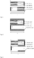
- the Figures 1 to 10 explain this by way of example, with the Figures 1 to 4 relate to the wall flow filter according to the invention, which only include the coatings Z and F, while the wall flow filter according to the invention according to Figures 5 to 10 additionally comprise the coating Y.
- figure 1 relates to a wall-flow filter according to the invention, in which the coating Z is located in the channels A on the surfaces O A and extends over 50% of the length L starting from the second end of the wall-flow filter substrate.
- the coating F is located in the channels E and extends over the entire length L.
- figure 2 relates to a wall-flow filter according to the invention, in which the coating Z is located in the channels A on the surfaces O A . However, starting from the second end of the wall flow filter substrate, it extends to 80% of the length L. The coating F is located in the channels E and extends over the entire length L.
- figure 3 relates to a wall-flow filter according to the invention, in which the coating Z is located in the porous walls and extends over the entire length L.
- the coating F is located in the channels E and also extends over the entire length L.
- figure 4 relates to a wall-flow filter according to the invention, in which the coating Z is located in the porous walls and extends over 50% of the length L, starting from the second end of the wall-flow filter substrate.
- the coating F is located in the channels E and extends over the entire length L.
- figure 5 relates to a wall flow filter according to the invention, which differs from that of figure 4 differs in that coating Z is over 50% of the length L on the surfaces O A and additional coating Y is in the porous walls over the entire length L.
- the coating F is located in the channels E and extends over the entire length L.
- figure 6 relates to a wall flow filter according to the invention, which differs from that of figure 4 differs in that coating Z extends over 50% of the length L on the surfaces O A and, in addition, coating Y in the porous walls extends over 50% of the length L, starting from the first end of the wall-flow filter substrate.
- the coating F is located in the channels E and extends over the entire length L.
- figure 7 relates to a wall-flow filter according to the invention, in which the coating Z is located in the channels A on the surfaces O A and extends over 50% of the length L.
- coating Y is located in channels E on surfaces OE and extends 50% of length L from the first end of the wall-flow filter substrate.
- Coating F is located in channels E and extends 50% of the length L from the second end of the wall-flow filter substrate.
- figure 8 relates to a wall-flow filter according to the invention, in which the coating Z is located in the porous walls and extends over the entire length L.
- coating Y is located in channels E on surfaces O E and extends 50% of length L from the first end of the wall-flow filter substrate.
- Coating F is located in channels E and extends 50% from the second end of wall-flow filter substrate of length L
- figure 9 relates to a wall-flow filter according to the invention, in which the coating Z is located in the porous walls and extends over 50% of the length L, starting from the second end of the wall-flow filter substrate.
- coating Y is located in channels E on surfaces O E and extends 50% of length L from the first end of the wall-flow filter substrate.
- Coating F is located in channels E and extends 50% from the second end of wall-flow filter substrate of length L
- figure 10 relates to a wall-flow filter according to the invention, in which the coating Z is located in the channels A on the surfaces O A and extends over 80% of the length L starting from the second end of the wall-flow filter substrate.
- coating Y is located in the porous walls and extends over the entire length L.
- Coating F is located in the channels E and extends over the entire length L.
- the wall-flow filter according to the invention can be produced by applying the coatings Z, F and, if present, Y to a wall-flow filter substrate.
- the catalytic activity is provided by coating the wall-flow filter substrate with the coating Z and, if present, with the coating Y, as determined by the person skilled in the art.
- the term coating is understood to mean the application of catalytically active materials to a wall-flow filter substrate.
- the coating takes on the actual catalytic function.
- the coating is carried out by the application of a correspondingly low-viscosity aqueous suspension of the catalytically active components - also called washcoat - in or on the wall of the wall flow filter substrate, for example according to EP1789190B1 .
- washcoat a correspondingly low-viscosity aqueous suspension of the catalytically active components
- the wall-flow filter substrate is in each case dried and optionally calcined at elevated temperature.
- the catalytically coated filter preferably has a loading of 20 g/l to 200 g/l, preferably 30 g/l to 150 g/l (coating Z or the sum of the coatings Z and Y).
- the most suitable loading level of a wall-coated filter depends on its cell density, wall thickness and porosity.
- the coating F can likewise be applied to the surfaces O E by the coating method described above, ie by means of a wet-chemical coating step. Thus, the coating F can first be coated on the surfaces OE and then, after calcination, the coatings Y, if present, and Z can be applied. Alternatively, the coatings Y, if present, and Z can be applied first and then the coating F can be coated on the surfaces OE.
- the suspensions required for coating are obtained by mixing the components and then grinding them to the desired particle size and adjusting the viscosity using an appropriate mill. If coating F is to contain sub-micron particles, they are added in particular after the grinding step and before the viscosity is adjusted.
- the suspension is generally first pumped into the channel E at a pumping rate of 25 to 500 ml/s. The suspension is then sucked off against the pumping direction with a first suction pulse and then, after turning it around, sucked off again with a second suction pulse in the pumping direction.
- the negative pressure of the second suction pulse is greater than or equal to the negative pressure of the first suction pulse, the ratio of the pressures of the first to the second suction pulse being 0.1 to 1, preferably 0.15 to 0.8 and particularly preferably 0 .2 to 0.75.
- the first suction pulse extends in particular over a period of 0.5 to 15 seconds.
- the second suction pulse also extends over a period of 0.5 to 15 seconds.
- the first suction pulse can be longer than the second suction pulse or the second suction pulse can be longer than the first suction pulse.
- a holding time of 0 to 200 seconds can be applied while the coating suspension remains in the channels E.
- the suspension for producing the coating F has a certain viscosity, which can be influenced with a large number of commercially available additives. These are well known to those skilled in the art.
- the viscosity of the suspension for producing the coating F is preferably in a range from 0.01 to 10 Pa s -1 , preferably from 0.02 to 7.5 Pa s -1 and particularly preferably in a range from 0.03 to 5 Pa s -1 set, measured at a shear rate of 1000 s -1 and a temperature of 23°C.
- the mass of the coating F is in particular 3 to 75 g/l, based on the volume of the wall flow substrate, preferably 5 to 60 g/l.
- the applied mass of the coating F can be varied depending on the wall-flow filter substrate used. It is advantageous if the ratio of the mass of the coating F to the average pore diameter of the wall-flow filter substrate, measured in ⁇ m, is 0.25 to 8, preferably 0.5 to 6.
- the catalytically coated wall-flow filters according to the invention differ from those that arise in the exhaust system of a vehicle due to ash deposits during operation.
- the catalytically active wall-flow filter substrates are provided with coating F in a targeted manner.
- the present invention therefore does not include wall-flow filters in which undefined ash deposits have occurred from the combustion of fuel, for example in the cylinder during driving or by means of a burner.
- the present invention therefore also does not include wall-flow filters in which defined ash deposits have taken place through dry coating of an air/powder aerosol.
- the catalytically coated wall flow filter according to the invention also has a high stability to condensation water, which usually collects in quantities of 10 to 1000 ml in the exhaust system.
- the coating F shows only a 0 to 5% loss in filtration performance after contact with more than 50 ml of water.
- the wall-flow filter according to the invention shows excellent filtration efficiency with only a moderate increase in exhaust back pressure compared to a wall-flow filter without the coating F in the fresh state.
- the wall flow filter according to the invention preferably shows an improvement in soot particle separation (filter effect) in the filter of at least 5%, preferably at least 10% and very particularly preferably at least 20% with a relative increase in the exhaust gas back pressure of the fresh wall flow filter of at most 40%, preferably at most 20% and most preferably at most 10% compared to a fresh filter coated with catalytically active material not treated with coating F.
- the slight increase in dynamic pressure is probably due to the fact that the inventive loading of the filter with coating F does not greatly reduce the cross section of the channels on the inlet side.
- coating F forms a porous structure, which has a positive effect on the dynamic pressure. Due to the coating F, a filter according to the invention also has a lower dynamic pressure after soot loading than an analogous filter without coating F, since this largely prevents the soot from penetrating into the porous filter wall. Coating Z imparts excellent three-way activity to the wall-flow filter according to the invention, while the optional coating Y is able to reduce the soot ignition temperature and thus facilitate soot burn-off.
- the present invention thus also relates to the use of a wall-flow filter according to the invention for reducing harmful exhaust gases from an internal combustion engine.
- the wall-flow filter according to the invention is used very advantageously in combination with a three-way catalytic converter, which in particular is connected to the second end of the wall-flow filter (ie is arranged on the outflow side when used as intended).
- the present invention further relates to an exhaust gas purification system which comprises a filter according to the invention and at least one further catalytic converter.
- at least one further catalyst is arranged upstream of the filter according to the invention. This is preferably a three-way catalytic converter or an oxidation catalytic converter or an NO x storage catalytic converter.
- at least one further catalyst is arranged downstream of the filter according to the invention. This is preferably a three-way catalytic converter or an SCR catalytic converter or an NO x storage catalytic converter or an ammonia slip catalytic converter.
- At least one further catalyst is arranged upstream of the filter according to the invention and at least one further catalyst is arranged downstream of the filter according to the invention.
- the upstream catalyst is preferably a three-way catalyst or an oxidation catalyst or a NO x storage catalyst and the downstream catalyst is a three-way catalyst or an SCR catalyst or a NO x storage catalyst or an ammonia slip catalyst.
- the preferred embodiments described for the wall-flow filter according to the invention also apply, mutatis mutandis, to the exhaust gas cleaning system mentioned here.
- the filter according to the invention is usually used primarily in internal combustion engines, in particular in internal combustion engines with direct injection or intake manifold injection. These are preferably stoichiometrically operated gasoline or natural gas engines.
- the engines are preferably turbocharged
- gasoline particulate filters differ significantly from the requirements for diesel particulate filters (DPF).
- Diesel engines without a DPF can have up to ten times higher particle emissions, based on the particle mass, than petrol engines without a GPF (Maricq et al., SAE 1999-01-01530).
- the petrol engine produces significantly fewer primary particles and the secondary particles (agglomerates) are significantly smaller than in the diesel engine.
- Gasoline engine emissions range from particle sizes smaller than 200 nm (Hall et al., SAE 1999-01-3530) to 400 nm ( Mathis et al., Atmospheric Environment 38 4347 ) with the maximum in the range from around 60 nm to 80 nm.
- the filtration of the nanoparticles in the GPF must mainly be carried out via diffusion separation.
- deposition by diffusion (Brownian motion) and electrostatic forces becomes increasingly important with decreasing size ( Hinds, W.: Aerosol technology: Properties and behavior and measurement of airborne particles. Wiley, 2nd edition 1999 ).
- Alumina stabilized with lanthana was combined with a first oxygen storage component comprising 40% by weight of ceria, zirconia, lanthana and praseodymia and a second oxygen storage component comprising 24% by weight of ceria, zirconia, lanthana and yttria in water suspended. Both oxygen storage components were used in equal parts. The weight ratio of alumina and oxygen storage component was 30:70. A palladium nitrate solution and a rhodium nitrate solution were then added to the suspension thus obtained, with constant stirring. The resulting coating suspension was used directly for coating a commercially available wall-flow filter substrate, with the coating being introduced into the porous filter wall over 100% of the substrate length.
- VGPF1 The total loading of this filter was 25 g/l, the total noble metal loading was 0.166 g/l, with palladium being used exclusively as the noble metal species.
- the coated filter thus obtained was dried and then calcined. It is hereinafter referred to as VGPF1.
- Example 1 Coating Z in combination with coating F: aluminum oxide stabilized with lanthana was combined with a first oxygen storage component which comprised 40% by weight of cerium oxide, zirconium oxide, lanthana and praseodymium oxide and a second oxygen storage component which contained 24% by weight. % comprised ceria, zirconia, lanthana and yttria suspended in water. Both oxygen storage components were used in equal parts. The weight ratio of alumina and oxygen storage component was 30:70. A palladium nitrate solution and a rhodium nitrate solution were then added to the suspension thus obtained, with constant stirring.
- the resulting coating suspension was used directly for coating a commercially available wall-flow filter substrate, with the coating being introduced into the porous filter wall over 100% of the substrate length.
- the total loading of this filter was 25 g/l, the total precious metal loading was 0.166 g/l, with palladium being used exclusively as the precious metal species.
- the coated filter thus obtained was dried and then calcined.
- the filter was then coated on the surfaces O E with a wet-chemical filtration efficiency-increasing membrane consisting of aluminum oxide.
- a suspension of a metal oxide with an average grain size of 5.7 ⁇ m was coated in a wet-chemical process. The suspension was first pumped into the substrate and then emptied with a weak suction pulse in the opposite direction to the pumping direction.
- the filter was then sucked off again with a second, stronger suction impulse in the direction of pumping.
- the coated filter thus obtained was dried and then calcined.
- the total loading of this filter was therefore 55 g/l, with 25 g/l being attributable to coating Z and 30 g/l to coating F. It is hereinafter referred to as GPF1.
- the two filters obtained in this way were then measured on a cold-blowing test rig in order to determine the pressure drop across the respective filter.
- a cold-blowing test rig At room temperature and a volume flow of 600 m 3 /h air, there is a back pressure of 16 mbar in the VGPF1 and 50 mbar in the GPF1.
- the filtration coating F only leads to a moderate increase in back pressure.
- the filters were examined with regard to their particle filtration efficiency.
- the filters were measured in an RTS-aggressive driving cycle in a position close to the engine between two particle counters.
- the filter GPF1 according to the invention has a filtration efficiency of 88.3% calculated from the particle values of the two particle counters, while the comparison filter VGPF1 only achieves a filtration efficiency of 68.4%.
- the combination of the filtration coating F and the three-way coating Z is particularly advantageous in terms of filtration efficiency.
Landscapes
- Chemical & Material Sciences (AREA)
- Engineering & Computer Science (AREA)
- Chemical Kinetics & Catalysis (AREA)
- Materials Engineering (AREA)
- Organic Chemistry (AREA)
- Combustion & Propulsion (AREA)
- Health & Medical Sciences (AREA)
- Mechanical Engineering (AREA)
- General Engineering & Computer Science (AREA)
- Environmental & Geological Engineering (AREA)
- Analytical Chemistry (AREA)
- General Chemical & Material Sciences (AREA)
- Oil, Petroleum & Natural Gas (AREA)
- Biomedical Technology (AREA)
- Toxicology (AREA)
- Catalysts (AREA)
- Filtering Materials (AREA)
Priority Applications (4)
| Application Number | Priority Date | Filing Date | Title |
|---|---|---|---|
| EP20214160.2A EP4015067A1 (fr) | 2020-12-15 | 2020-12-15 | Filtre à particules catalytiquement actif à efficacité de filtration élevée |
| CN202180081684.0A CN116615283A (zh) | 2020-12-15 | 2021-12-14 | 具有高度过滤效率的催化活性颗粒过滤器 |
| US18/256,412 US20240033687A1 (en) | 2020-12-15 | 2021-12-14 | Catalytically active particle filter with a high degree of filtering efficiency |
| PCT/EP2021/085657 WO2022129027A1 (fr) | 2020-12-15 | 2021-12-14 | Filtre à particules catalytiquement actif à haut degré de rendement de filtration |
Applications Claiming Priority (1)
| Application Number | Priority Date | Filing Date | Title |
|---|---|---|---|
| EP20214160.2A EP4015067A1 (fr) | 2020-12-15 | 2020-12-15 | Filtre à particules catalytiquement actif à efficacité de filtration élevée |
Publications (1)
| Publication Number | Publication Date |
|---|---|
| EP4015067A1 true EP4015067A1 (fr) | 2022-06-22 |
Family
ID=73854556
Family Applications (1)
| Application Number | Title | Priority Date | Filing Date |
|---|---|---|---|
| EP20214160.2A Pending EP4015067A1 (fr) | 2020-12-15 | 2020-12-15 | Filtre à particules catalytiquement actif à efficacité de filtration élevée |
Country Status (4)
| Country | Link |
|---|---|
| US (1) | US20240033687A1 (fr) |
| EP (1) | EP4015067A1 (fr) |
| CN (1) | CN116615283A (fr) |
| WO (1) | WO2022129027A1 (fr) |
Cited By (3)
| Publication number | Priority date | Publication date | Assignee | Title |
|---|---|---|---|---|
| DE102021125536A1 (de) | 2021-10-01 | 2023-04-06 | Umicore Ag & Co. Kg | Katalytisch aktiver Partikelfilter mit hoher Filtrationseffizienz |
| DE102022002854A1 (de) * | 2022-08-05 | 2024-02-08 | Umicore Ag & Co. Kg | Katalytisch aktiver Partikelfilter mit hoher Filtrationseffizienz und Oxidationsfunktion |
| WO2024161104A1 (fr) * | 2023-01-30 | 2024-08-08 | Johnson Matthey Public Limited Company | Filtre à écoulement sur paroi catalytique |
Families Citing this family (1)
| Publication number | Priority date | Publication date | Assignee | Title |
|---|---|---|---|---|
| EP4581251A1 (fr) * | 2022-09-27 | 2025-07-09 | BASF Mobile Emissions Catalysts LLC | Filtre à particules catalysées |
Citations (23)
| Publication number | Priority date | Publication date | Assignee | Title |
|---|---|---|---|---|
| US4609563A (en) | 1985-02-28 | 1986-09-02 | Engelhard Corporation | Metered charge system for catalytic coating of a substrate |
| JPH01151706A (ja) | 1987-12-08 | 1989-06-14 | Toyota Central Res & Dev Lab Inc | 可燃性微粒子と窒素酸化物を除去するための触媒及びフィルター |
| WO1999047260A1 (fr) | 1998-03-19 | 1999-09-23 | Johnson Matthey Public Limited Company | Appareil de revetement de support monolithique et son procede de fabrication |
| US6478874B1 (en) | 1999-08-06 | 2002-11-12 | Engelhard Corporation | System for catalytic coating of a substrate |
| EP1136462B1 (fr) | 2000-03-23 | 2004-08-04 | Umicore AG & Co. KG | Procédé de revêtement partiel d'un corps de support |
| WO2005016497A1 (fr) | 2003-08-05 | 2005-02-24 | Engelhard Corporation | Systeme de traitement d'emissions et procede d'utilisation d'un filtre a reduction catalytique selective (scr) |
| EP1716903A1 (fr) * | 2004-02-10 | 2006-11-02 | Cataler Corporation | Proce de fabrication de filtre catalytique |
| WO2010015573A2 (fr) | 2008-08-06 | 2010-02-11 | Basf Se | Dispositif et procédé de positionnement avec une table d'indexage rotative pour des catalyseurs pour automobile et chimiques à base de monolithe |
| WO2011151711A1 (fr) | 2010-06-02 | 2011-12-08 | Johnson Matthey Public Limited Company | Filtre à particules diesel |
| EP2415522A1 (fr) | 2009-04-03 | 2012-02-08 | Cataler Corporation | Procédé et dispositif de fabrication d'un catalyseur de contrôle d'émission de gaz d'échappement et buse utilisée avec le dispositif |
| WO2012030534A1 (fr) | 2010-09-01 | 2012-03-08 | Dow Global Technologies Llc | Procédé pour l'application d'une couche de discrimination sur des filtres poreux en céramique via des assemblages poreux préfabriqués en suspension dans un gaz |
| EP2502661A2 (fr) | 2011-03-25 | 2012-09-26 | NGK Insulators, Ltd. | Filtre en nid d'abeille et son procédé de fabrication |
| US8277880B2 (en) | 2010-04-22 | 2012-10-02 | Ngk Insulators, Ltd. | Method for manufacturing plugged honeycomb structure |
| US8388721B2 (en) | 2006-11-30 | 2013-03-05 | Hitachi Metals, Ltd. | Ceramic honeycomb filter and its production method |
| EP2521618B1 (fr) | 2010-01-04 | 2013-08-28 | Johnson Matthey PLC | Procédé de revêtement d'un substrat monolithique avec un constituant de catalyseur |
| JP5378659B2 (ja) | 2007-06-07 | 2013-12-25 | 株式会社キャタラー | 貴金属担持方法 |
| EP2723476A1 (fr) * | 2011-06-21 | 2014-04-30 | Johnson Matthey PLC | Substrat catalysé et système d'échappement pour moteurs à combustion interne |
| EP2727640A1 (fr) | 2012-11-06 | 2014-05-07 | Fraunhofer-Gesellschaft zur Förderung der angewandten Forschung e.V. | Filtre à particules |
| EP2502662B1 (fr) | 2011-03-24 | 2014-06-11 | NGK Insulators, Ltd. | Filtre en nid d'abeille et son procédé de fabrication |
| JP2014205108A (ja) | 2013-04-12 | 2014-10-30 | 株式会社キャタラー | スラリー塗布装置 |
| EP1789190B1 (fr) | 2004-08-21 | 2017-06-14 | Umicore AG & Co. KG | Procede pour revetir un filtre a ecoulement sur paroi d'une composition de revetement |
| WO2018115900A1 (fr) | 2016-12-23 | 2018-06-28 | Johnson Matthey Public Limited Company | Filtre à particules d'essence |
| DE102018127955A1 (de) * | 2018-11-08 | 2020-05-14 | Umicore Ag & Co. Kg | Katalytisch aktiver Partikelfilter mit hoher Filtrationseffizienz |
Family Cites Families (1)
| Publication number | Priority date | Publication date | Assignee | Title |
|---|---|---|---|---|
| US9764287B2 (en) * | 2015-11-06 | 2017-09-19 | Paccar Inc | Binary catalyst based selective catalytic reduction filter |
-
2020
- 2020-12-15 EP EP20214160.2A patent/EP4015067A1/fr active Pending
-
2021
- 2021-12-14 CN CN202180081684.0A patent/CN116615283A/zh active Pending
- 2021-12-14 WO PCT/EP2021/085657 patent/WO2022129027A1/fr not_active Ceased
- 2021-12-14 US US18/256,412 patent/US20240033687A1/en active Pending
Patent Citations (24)
| Publication number | Priority date | Publication date | Assignee | Title |
|---|---|---|---|---|
| US4609563A (en) | 1985-02-28 | 1986-09-02 | Engelhard Corporation | Metered charge system for catalytic coating of a substrate |
| JPH01151706A (ja) | 1987-12-08 | 1989-06-14 | Toyota Central Res & Dev Lab Inc | 可燃性微粒子と窒素酸化物を除去するための触媒及びフィルター |
| WO1999047260A1 (fr) | 1998-03-19 | 1999-09-23 | Johnson Matthey Public Limited Company | Appareil de revetement de support monolithique et son procede de fabrication |
| EP1064094B1 (fr) | 1998-03-19 | 2002-09-25 | Johnson Matthey Public Limited Company | Appareil de revetement de support monolithique et son procede de fabrication |
| US6478874B1 (en) | 1999-08-06 | 2002-11-12 | Engelhard Corporation | System for catalytic coating of a substrate |
| EP1136462B1 (fr) | 2000-03-23 | 2004-08-04 | Umicore AG & Co. KG | Procédé de revêtement partiel d'un corps de support |
| WO2005016497A1 (fr) | 2003-08-05 | 2005-02-24 | Engelhard Corporation | Systeme de traitement d'emissions et procede d'utilisation d'un filtre a reduction catalytique selective (scr) |
| EP1716903A1 (fr) * | 2004-02-10 | 2006-11-02 | Cataler Corporation | Proce de fabrication de filtre catalytique |
| EP1789190B1 (fr) | 2004-08-21 | 2017-06-14 | Umicore AG & Co. KG | Procede pour revetir un filtre a ecoulement sur paroi d'une composition de revetement |
| US8388721B2 (en) | 2006-11-30 | 2013-03-05 | Hitachi Metals, Ltd. | Ceramic honeycomb filter and its production method |
| JP5378659B2 (ja) | 2007-06-07 | 2013-12-25 | 株式会社キャタラー | 貴金属担持方法 |
| WO2010015573A2 (fr) | 2008-08-06 | 2010-02-11 | Basf Se | Dispositif et procédé de positionnement avec une table d'indexage rotative pour des catalyseurs pour automobile et chimiques à base de monolithe |
| EP2415522A1 (fr) | 2009-04-03 | 2012-02-08 | Cataler Corporation | Procédé et dispositif de fabrication d'un catalyseur de contrôle d'émission de gaz d'échappement et buse utilisée avec le dispositif |
| EP2521618B1 (fr) | 2010-01-04 | 2013-08-28 | Johnson Matthey PLC | Procédé de revêtement d'un substrat monolithique avec un constituant de catalyseur |
| US8277880B2 (en) | 2010-04-22 | 2012-10-02 | Ngk Insulators, Ltd. | Method for manufacturing plugged honeycomb structure |
| WO2011151711A1 (fr) | 2010-06-02 | 2011-12-08 | Johnson Matthey Public Limited Company | Filtre à particules diesel |
| WO2012030534A1 (fr) | 2010-09-01 | 2012-03-08 | Dow Global Technologies Llc | Procédé pour l'application d'une couche de discrimination sur des filtres poreux en céramique via des assemblages poreux préfabriqués en suspension dans un gaz |
| EP2502662B1 (fr) | 2011-03-24 | 2014-06-11 | NGK Insulators, Ltd. | Filtre en nid d'abeille et son procédé de fabrication |
| EP2502661A2 (fr) | 2011-03-25 | 2012-09-26 | NGK Insulators, Ltd. | Filtre en nid d'abeille et son procédé de fabrication |
| EP2723476A1 (fr) * | 2011-06-21 | 2014-04-30 | Johnson Matthey PLC | Substrat catalysé et système d'échappement pour moteurs à combustion interne |
| EP2727640A1 (fr) | 2012-11-06 | 2014-05-07 | Fraunhofer-Gesellschaft zur Förderung der angewandten Forschung e.V. | Filtre à particules |
| JP2014205108A (ja) | 2013-04-12 | 2014-10-30 | 株式会社キャタラー | スラリー塗布装置 |
| WO2018115900A1 (fr) | 2016-12-23 | 2018-06-28 | Johnson Matthey Public Limited Company | Filtre à particules d'essence |
| DE102018127955A1 (de) * | 2018-11-08 | 2020-05-14 | Umicore Ag & Co. Kg | Katalytisch aktiver Partikelfilter mit hoher Filtrationseffizienz |
Non-Patent Citations (2)
| Title |
|---|
| HINDS, W: "Aerosol technology: Properties and behavior and measurement of airborne particles", vol. 2, 1999, WILEY |
| MATHIS ET AL., ATMOSPHERIC ENVIRONMENT, vol. 38, pages 4347 |
Cited By (3)
| Publication number | Priority date | Publication date | Assignee | Title |
|---|---|---|---|---|
| DE102021125536A1 (de) | 2021-10-01 | 2023-04-06 | Umicore Ag & Co. Kg | Katalytisch aktiver Partikelfilter mit hoher Filtrationseffizienz |
| DE102022002854A1 (de) * | 2022-08-05 | 2024-02-08 | Umicore Ag & Co. Kg | Katalytisch aktiver Partikelfilter mit hoher Filtrationseffizienz und Oxidationsfunktion |
| WO2024161104A1 (fr) * | 2023-01-30 | 2024-08-08 | Johnson Matthey Public Limited Company | Filtre à écoulement sur paroi catalytique |
Also Published As
| Publication number | Publication date |
|---|---|
| WO2022129027A1 (fr) | 2022-06-23 |
| US20240033687A1 (en) | 2024-02-01 |
| CN116615283A (zh) | 2023-08-18 |
Similar Documents
| Publication | Publication Date | Title |
|---|---|---|
| EP3877633B1 (fr) | Filtre à particules catalytiquement actif ayant une efficacité de filtration élevée | |
| EP3727653B1 (fr) | Filtre à particules à activité catalytique | |
| EP2181749B2 (fr) | Filtre à particules diesel doté de propriétés de pression dynamique améliorées | |
| EP3601755B1 (fr) | Filtre a particules | |
| DE102018110804B4 (de) | Beschichteter Wandflussfilter | |
| WO2022129027A1 (fr) | Filtre à particules catalytiquement actif à haut degré de rendement de filtration | |
| EP3505246B1 (fr) | Filtre à particules à effet catalityque actif | |
| DE102012220181A1 (de) | Partikelfilter | |
| WO2019121365A1 (fr) | Filtre à particules à activité catalytique | |
| EP4015065B1 (fr) | Filtre à particules catalytiquement actif à efficacité de filtration élevée | |
| EP4015064B1 (fr) | Filtre à particules catalytiquement actif à efficacité de filtration élevée | |
| WO2022129023A1 (fr) | Filtre à particules catalytiquement actif ayant un haut degré d'efficacité de filtration | |
| DE102016123228A1 (de) | Verfahren zum Herstellen eines katalytischen Partikelfilters | |
| EP3946692A1 (fr) | Filtre à particules à activité catalytique | |
| EP3946691A1 (fr) | Filtre à particules à activité catalytique | |
| WO2023052580A1 (fr) | Filtre à particules catalytiquement actif à grand rendement de filtration | |
| DE102021107130B4 (de) | Vorrichtung zur Erhöhung der Frischfiltration von Benzinpartikelfiltern | |
| EP4313376B1 (fr) | Filtre à particules pour gaz d'échappement de moteurs à essence | |
| DE102022002854A1 (de) | Katalytisch aktiver Partikelfilter mit hoher Filtrationseffizienz und Oxidationsfunktion |
Legal Events
| Date | Code | Title | Description |
|---|---|---|---|
| PUAI | Public reference made under article 153(3) epc to a published international application that has entered the european phase |
Free format text: ORIGINAL CODE: 0009012 |
|
| STAA | Information on the status of an ep patent application or granted ep patent |
Free format text: STATUS: THE APPLICATION HAS BEEN PUBLISHED |
|
| AK | Designated contracting states |
Kind code of ref document: A1 Designated state(s): AL AT BE BG CH CY CZ DE DK EE ES FI FR GB GR HR HU IE IS IT LI LT LU LV MC MK MT NL NO PL PT RO RS SE SI SK SM TR |
|
| STAA | Information on the status of an ep patent application or granted ep patent |
Free format text: STATUS: REQUEST FOR EXAMINATION WAS MADE |
|
| 17P | Request for examination filed |
Effective date: 20221222 |
|
| RBV | Designated contracting states (corrected) |
Designated state(s): AL AT BE BG CH CY CZ DE DK EE ES FI FR GB GR HR HU IE IS IT LI LT LU LV MC MK MT NL NO PL PT RO RS SE SI SK SM TR |
|
| RAP3 | Party data changed (applicant data changed or rights of an application transferred) |
Owner name: UMICORE AG & CO. KG |