EP4015151A1 - Zweiteiliger blindbefestiger und installationswerkzeug - Google Patents
Zweiteiliger blindbefestiger und installationswerkzeug Download PDFInfo
- Publication number
- EP4015151A1 EP4015151A1 EP21215522.0A EP21215522A EP4015151A1 EP 4015151 A1 EP4015151 A1 EP 4015151A1 EP 21215522 A EP21215522 A EP 21215522A EP 4015151 A1 EP4015151 A1 EP 4015151A1
- Authority
- EP
- European Patent Office
- Prior art keywords
- tool
- axis
- collet
- sleeve
- cylindrical body
- Prior art date
- Legal status (The legal status is an assumption and is not a legal conclusion. Google has not performed a legal analysis and makes no representation as to the accuracy of the status listed.)
- Granted
Links
Images








Classifications
-
- B—PERFORMING OPERATIONS; TRANSPORTING
- B25—HAND TOOLS; PORTABLE POWER-DRIVEN TOOLS; MANIPULATORS
- B25B—TOOLS OR BENCH DEVICES NOT OTHERWISE PROVIDED FOR, FOR FASTENING, CONNECTING, DISENGAGING, OR HOLDING
- B25B27/00—Hand tools, specially adapted for fitting together or separating parts or objects whether or not involving some deformation, not otherwise provided for
- B25B27/0007—Tools for fixing internally screw-threaded tubular fasteners
- B25B27/0014—Tools for fixing internally screw-threaded tubular fasteners motor-driven
-
- B—PERFORMING OPERATIONS; TRANSPORTING
- B25—HAND TOOLS; PORTABLE POWER-DRIVEN TOOLS; MANIPULATORS
- B25B—TOOLS OR BENCH DEVICES NOT OTHERWISE PROVIDED FOR, FOR FASTENING, CONNECTING, DISENGAGING, OR HOLDING
- B25B21/00—Portable power-driven screw or nut setting or loosening tools; Attachments for drilling apparatus serving the same purpose
-
- B—PERFORMING OPERATIONS; TRANSPORTING
- B21—MECHANICAL METAL-WORKING WITHOUT ESSENTIALLY REMOVING MATERIAL; PUNCHING METAL
- B21J—FORGING; HAMMERING; PRESSING METAL; RIVETING; FORGE FURNACES
- B21J15/00—Riveting
- B21J15/02—Riveting procedures
- B21J15/04—Riveting hollow rivets mechanically
-
- B—PERFORMING OPERATIONS; TRANSPORTING
- B21—MECHANICAL METAL-WORKING WITHOUT ESSENTIALLY REMOVING MATERIAL; PUNCHING METAL
- B21J—FORGING; HAMMERING; PRESSING METAL; RIVETING; FORGE FURNACES
- B21J15/00—Riveting
- B21J15/10—Riveting machines
- B21J15/105—Portable riveters
-
- B—PERFORMING OPERATIONS; TRANSPORTING
- B21—MECHANICAL METAL-WORKING WITHOUT ESSENTIALLY REMOVING MATERIAL; PUNCHING METAL
- B21J—FORGING; HAMMERING; PRESSING METAL; RIVETING; FORGE FURNACES
- B21J15/00—Riveting
- B21J15/10—Riveting machines
- B21J15/12—Riveting machines with tools or tool parts having a movement additional to the feed movement, e.g. spin
-
- B—PERFORMING OPERATIONS; TRANSPORTING
- B25—HAND TOOLS; PORTABLE POWER-DRIVEN TOOLS; MANIPULATORS
- B25B—TOOLS OR BENCH DEVICES NOT OTHERWISE PROVIDED FOR, FOR FASTENING, CONNECTING, DISENGAGING, OR HOLDING
- B25B23/00—Details of, or accessories for, spanners, wrenches, screwdrivers
-
- F—MECHANICAL ENGINEERING; LIGHTING; HEATING; WEAPONS; BLASTING
- F16—ENGINEERING ELEMENTS AND UNITS; GENERAL MEASURES FOR PRODUCING AND MAINTAINING EFFECTIVE FUNCTIONING OF MACHINES OR INSTALLATIONS; THERMAL INSULATION IN GENERAL
- F16B—DEVICES FOR FASTENING OR SECURING CONSTRUCTIONAL ELEMENTS OR MACHINE PARTS TOGETHER, e.g. NAILS, BOLTS, CIRCLIPS, CLAMPS, CLIPS OR WEDGES; JOINTS OR JOINTING
- F16B19/00—Bolts without screw-thread; Pins, including deformable elements; Rivets
- F16B19/04—Rivets; Spigots or the like fastened by riveting
- F16B19/08—Hollow rivets; Multi-part rivets
- F16B19/10—Hollow rivets; Multi-part rivets fastened by expanding mechanically
- F16B19/1027—Multi-part rivets
- F16B19/1036—Blind rivets
- F16B19/1045—Blind rivets fastened by a pull - mandrel or the like
- F16B19/1054—Blind rivets fastened by a pull - mandrel or the like the pull-mandrel or the like being frangible
-
- F—MECHANICAL ENGINEERING; LIGHTING; HEATING; WEAPONS; BLASTING
- F16—ENGINEERING ELEMENTS AND UNITS; GENERAL MEASURES FOR PRODUCING AND MAINTAINING EFFECTIVE FUNCTIONING OF MACHINES OR INSTALLATIONS; THERMAL INSULATION IN GENERAL
- F16B—DEVICES FOR FASTENING OR SECURING CONSTRUCTIONAL ELEMENTS OR MACHINE PARTS TOGETHER, e.g. NAILS, BOLTS, CIRCLIPS, CLAMPS, CLIPS OR WEDGES; JOINTS OR JOINTING
- F16B19/00—Bolts without screw-thread; Pins, including deformable elements; Rivets
- F16B19/04—Rivets; Spigots or the like fastened by riveting
- F16B19/08—Hollow rivets; Multi-part rivets
- F16B19/10—Hollow rivets; Multi-part rivets fastened by expanding mechanically
- F16B19/1027—Multi-part rivets
- F16B19/1036—Blind rivets
- F16B19/1045—Blind rivets fastened by a pull - mandrel or the like
- F16B19/1072—Blind rivets fastened by a pull - mandrel or the like the pull-mandrel or the like comprising a thread and being rotated with respect to the rivet, thereby mechanically expanding and fastening the rivet
-
- F—MECHANICAL ENGINEERING; LIGHTING; HEATING; WEAPONS; BLASTING
- F16—ENGINEERING ELEMENTS AND UNITS; GENERAL MEASURES FOR PRODUCING AND MAINTAINING EFFECTIVE FUNCTIONING OF MACHINES OR INSTALLATIONS; THERMAL INSULATION IN GENERAL
- F16B—DEVICES FOR FASTENING OR SECURING CONSTRUCTIONAL ELEMENTS OR MACHINE PARTS TOGETHER, e.g. NAILS, BOLTS, CIRCLIPS, CLAMPS, CLIPS OR WEDGES; JOINTS OR JOINTING
- F16B31/00—Screwed connections specially modified in view of tensile load; Break-bolts
- F16B31/02—Screwed connections specially modified in view of tensile load; Break-bolts for indicating the attainment of a particular tensile load or limiting tensile load
- F16B31/021—Screwed connections specially modified in view of tensile load; Break-bolts for indicating the attainment of a particular tensile load or limiting tensile load by means of a frangible part
-
- F—MECHANICAL ENGINEERING; LIGHTING; HEATING; WEAPONS; BLASTING
- F16—ENGINEERING ELEMENTS AND UNITS; GENERAL MEASURES FOR PRODUCING AND MAINTAINING EFFECTIVE FUNCTIONING OF MACHINES OR INSTALLATIONS; THERMAL INSULATION IN GENERAL
- F16B—DEVICES FOR FASTENING OR SECURING CONSTRUCTIONAL ELEMENTS OR MACHINE PARTS TOGETHER, e.g. NAILS, BOLTS, CIRCLIPS, CLAMPS, CLIPS OR WEDGES; JOINTS OR JOINTING
- F16B37/00—Nuts or like thread-engaging members
- F16B37/04—Devices for fastening nuts to surfaces, e.g. sheets, plates
- F16B37/06—Devices for fastening nuts to surfaces, e.g. sheets, plates by means of welding or riveting
- F16B37/062—Devices for fastening nuts to surfaces, e.g. sheets, plates by means of welding or riveting by means of riveting
- F16B37/065—Devices for fastening nuts to surfaces, e.g. sheets, plates by means of welding or riveting by means of riveting by deforming the material of the nut
- F16B37/067—Devices for fastening nuts to surfaces, e.g. sheets, plates by means of welding or riveting by means of riveting by deforming the material of the nut the material of the nut being deformed by a threaded member generating axial movement of the threaded part of the nut, e.g. blind rivet type
-
- F—MECHANICAL ENGINEERING; LIGHTING; HEATING; WEAPONS; BLASTING
- F16—ENGINEERING ELEMENTS AND UNITS; GENERAL MEASURES FOR PRODUCING AND MAINTAINING EFFECTIVE FUNCTIONING OF MACHINES OR INSTALLATIONS; THERMAL INSULATION IN GENERAL
- F16B—DEVICES FOR FASTENING OR SECURING CONSTRUCTIONAL ELEMENTS OR MACHINE PARTS TOGETHER, e.g. NAILS, BOLTS, CIRCLIPS, CLAMPS, CLIPS OR WEDGES; JOINTS OR JOINTING
- F16B5/00—Joining sheets or plates, e.g. panels, to one another or to strips or bars parallel to them
- F16B5/04—Joining sheets or plates, e.g. panels, to one another or to strips or bars parallel to them by means of riveting
Definitions
- the present disclosure relates generally to fasteners and more particularly to blind fasteners having a core bolt and a nut around the core bolt for connecting panels from one side of the panels.
- a blind fastener is typically used to secure multiple panels together and to be installed from one side (i.e., a front side) of the panels.
- the blind fastener may include a core bolt and a sleeve surrounding the core bolt, which are inserted into a hole of the panels.
- a portion of the sleeve adjacent to a rear side of the panel may be deformed during installation of the fastener.
- the deformed portion of the sleeve provides a bearing surface to induce preload in the fastener such that the panels can be clamped together.
- the core bolt may be rotated to provide a preload to the fastener.
- a front portion of the core bolt may break off.
- the break-off point of the typical core bolt cannot be controlled and rotation of the nut relative to the bolt typically needs to be controlled.
- Typical fasteners need to be prepared for painting by post-installation grinding to be made flush with the panels when the break-off point is located outside the countersunk head of the sleeve.
- the typical fastener does not include a torque control feature. When excessive torque is applied to the fastener, the sleeve of the fastener may flare out to form a tulip configuration, resulting in a defective installation.
- a tool for installing a blind fastener including a bolt and a nut includes a base, a collet, a socket assembly, a drive body, and a mode clutch.
- the collet is coupled to the base and disposed about an axis.
- the collet is configured to selectively engage a tool engagement portion of the nut.
- the socket assembly includes a socket housing and a plurality of rollers.
- the socket housing is rotatable relative to the collet and defines a bore disposed about the axis.
- the rollers are spaced circumferentially about the axis. A surface of each roller is configured to engage a cylindrical tool engagement portion of the bolt within the bore to rotate the bolt about the axis.
- the drive body is coupled to the socket housing and configured to rotate the socket housing about the axis relative to the base.
- the mode clutch is configured to selectively couple the socket housing with the collet for common rotation about the axis.
- the rollers are cylindrical bodies oriented parallel to the axis;
- the tool further includes an outer sleeve disposed about the collet, wherein the collet includes a plurality of prongs extending radially inward and configured to engage the tool engagement portion of the nut, the outer sleeve being movable between a first sleeve position and a second sleeve position, wherein when the outer sleeve is in the first sleeve position, the prongs are further radially inward than when in the second sleeve position; the outer sleeve is biased toward the first radial position;
- the collet includes a collet sleeve, the prongs extending axially from the collet s
- a blind fastener for connecting a plurality of workpieces includes a bolt and a nut.
- the bolt includes a shaft, a bolt head, and a lug.
- the bolt head is disposed between the shaft and the lug and extends radially outward from the shaft.
- An end of the shaft opposite the bolt head defines external threads.
- the lug includes a first tool engagement portion and a first frangible portion that frangibly couples the lug to the bolt head.
- the first tool engagement portion defines a cylindrical outer surface configured to be engaged by a tool.
- a nut includes a sleeve, a nut head, and a handling member.
- the sleeve defines a central bore configured to receive the shaft and defines internal threads configured to mate with the external threads.
- the nut head is disposed between the handling member and the sleeve.
- the nut head extends radially outward from the sleeve and defines a recess configured to receive the bolt head.
- the handling member is configured to surround at least a portion of the lug.
- the handling member includes a second frangible portion and a second tool engagement portion. The second frangible portion frangibly couples the second tool engagement portion to the nut head.
- an end surface of the bolt head is flush with or recessed from an end surface of the nut head when the bolt is fully threaded into the nut;
- the first frangible portion is configured to break off from the bolt head such that an end surface of the bolt head is flush with or recessed from a front surface of the plurality of workpieces, and the second frangible portion is configured to break off from the nut head such that an end surface of the nut head is flush with or recessed from the front surface;
- the lug tapers radially inward from the cylindrical outer surface to a terminal end portion of the bolt;
- the handling member tapers radially inward from the second tool engagement portion to a terminal end portion of the nut;
- the second frangible portion is entirely radially inward of an outermost perimeter of the nut head;
- the handling member defines a bore having a diameter equal to an outermost diameter of the recess; a radially outermost surface of the lug is disposed radially outward of a bore defined by the handling
- a blind fastener 10 includes a bolt 14 and nut 18 that are configured to be matingly fitted together when positioned coaxially along a central axis 22.
- the bolt 14 is a single, integral piece of material and the nut 18 is a separate, single, integral piece of material.
- the bolt 14 and nut 18 can be formed from any suitable type of material such as a metal or alloy material for example.
- the bolt 14 can be formed of the same material as the nut 18 or can be a different suitable material.
- the blind fastener 10 can be similar to the blind fastener of U.S. Patent Application No. 16/201,775 ( U.S. Pub. No.
- the blind fastener 10 secures a first workpiece 26 to a second workpiece 30.
- the workpieces 26, 30 are plates or panels formed of any suitable material, such as metal (e.g., aluminum), carbon fiber composite or other suitable material for a given application.
- the first workpiece 26 and the second workpiece 30 each define apertures that cooperate when aligned to form an aperture 50 through a front surface 34 of the first workpiece 26 and through a back surface 46 of the second workpiece 30.
- the aperture 50 can be countersunk or counter bored from the first front surface 34.
- the aperture 50 is counter sunk such that it includes a cylindrical inner bore 54 and a contact surface 58 that extends axially at an angle between the inner bore 54 and the first front surface 34.
- the bolt 14 includes a shaft 110, a bolt head 114, and a lug 118 that are disposed about the axis 22.
- the shaft 110 is generally cylindrical and includes a stem 122 and a threaded portion that defines external threads 126.
- the external threads 126 begin at one terminal end 130 of the bolt 14.
- the stem 122 is disposed axially between the threads 126 and the bolt head 114.
- the stem 122 is a generally smooth cylinder with a diameter that is greater than or equal to the major diameter of the external threads 126.
- the external threads 126 extend axially along the shaft 110 until terminating adjacent to the stem 122, though other configurations can be used.
- a sealant or a seal can be disposed between the termination of the external threads 126 and the stem 122 or can be disposed along the stem 122, to seal with the inner surface of the nut 18.
- the seal (not shown) is configured to inhibit passage of fluids, such as water, oil, fuel, etc.
- the seal (not shown) can be an elastomeric body, such as an O-ring for example.
- the bolt head 114 is located at an end of the stem 122 that is opposite the external threads 126.
- the bolt head 114 extends radially outward of the stem 122.
- the bolt head 114 includes a clamp surface 138, a radially outermost perimeter 142, and a first end surface 146.
- the clamp surface 138 extends radially outward from the stem 122 at an angle such that the clamp surface 138 is generally conical in shape, though other configurations can be used.
- the perimeter 142 extends axially between the clamp surface 138 and the first end surface 146. In the example provided, the perimeter 142 is generally parallel with the axis 22, though other configurations can be used.
- the first end surface 146 faces axially away from the stem 122. In the example provided, the first end surface 146 is generally perpendicular to the axis 22, though other configurations can be used.
- the lug 118 includes a first tool engagement portion 150 and a first frangible portion 154.
- the lug 118 can also include a rim 158 extending axially between the first tool engagement portion 150 and the first frangible portion 154.
- the first tool engagement portion 150 defines the other terminal end 162 of the bolt 14, opposite the external threads 126.
- the first tool engagement portion 150 is configured to be engaged by a tool 510 ( FIG. 5 ) to impart torque about the axis 22.
- the first tool engagement portion 150 has a cylindrical surface 156.
- the cylindrical surface 156 extends the entire length of the first tool engagement portion 150.
- the cylindrical surface 156 is a generally smooth surface, though other configurations can be used, such as a rough surface or a knurled surface for example.
- the first tool engagement portion is 150 devoid of flat tool engagement surfaces and has a constant diameter along its length from the rim 158 to the terminal end 162 with the exception of an optional annular chamfer 152 at the terminal end 162 that can guide the tool 510 ( FIG. 5 ) onto the first tool engagement portion 150.
- the tool 510 ( FIG. 5 ) is configured to engage the cylindrical surface 156 of the first tool engagement portion 150
- the rim 158 is axially between the first tool engagement portion 150 to the first frangible portion 154 and extends radially outward from the first frangible portion 154 to the first tool engagement portion 150.
- the rim 158 has a generally frustoconical shape that widens with increased distance from the first frangible portion 154.
- the first frangible portion 154 frangibly couples the rim 158 to the bolt head 114.
- the outer surface 166 of the first frangible portion 154 is generally cylindrical in shape and has a diameter that is equal to or less than the outermost diameter of the perimeter 142 of the bolt head 114.
- the first frangible portion 154 narrows from the outer surface 166 to a break-neck 174 that joins the first end surface 146 of the bolt head 114 with the lug 118.
- the diameter of the break-neck 174 is also less than the diameter of the stem 122 and extends around a full circumference of the bolt 14.
- the nut 18 in the example provided is formed from a single, integral piece of material and includes a sleeve 210, a nut head 214, and a handling member 218 disposed about the axis 22.
- the sleeve 210 is a generally cylindrical body. One end of the sleeve 210 defines a terminal end 222 of the nut opposite the nut head 214.
- the sleeve 210 is received in the inner bore 54 ( FIG. 4 ) of the first and second workpieces 26, 30 ( FIG. 4 ).
- the sleeve 210 defines a central bore 230 coaxial with the axis 22 and includes internal threads 234.
- the internal threads 234 are configured to threadably engage the external threads 126 of the bolt 14.
- the first bore 230 has a diameter that is slightly greater than the diameter of the stem 122 so that the shaft 110 can be rotatably received in the first bore 230.
- the sleeve 210 can include a ductile region 238 between internal threads 234 and the nut head 214.
- the ductile region has a hardness that is less than a hardness of the rest of the nut 18.
- the nut head 214, the region of the sleeve 210 that is surrounded by the first and second workpieces 26, 30, and the region of the sleeve 210 that includes the internal threads 234 has a first hardness value, while the ductile region 238 can have a significantly lower hardness value. This significantly lower hardness value can be achieved by band annealing the sleeve 210 for example.
- the nut head 214 is located at an end of the sleeve 210 that is opposite the internal threads 234 and extends radially outward of the sleeve 210.
- the nut head 214 includes a recess 242, a clamp surface 246, and a second end surface 250.
- the clamp surface 246 extends radially outward from the sleeve 210 at an angle that forms a generally conical shape, though other configurations can be used.
- a perimeter 254 of the nut head 214 is defined by the junction of the clamp surface 246 and the second end surface 250.
- the second end surface 250 faces axially away from the sleeve 210 and can be generally perpendicular to the axis 22, though other configurations can be used.
- the recess 242 is disposed concentrically about the axis 22 and configured to receive the bolt head 114.
- the recess 242 has an inner wall surface 258 and a contact surface 262.
- the contact surface 262 extends radially outward from the first bore 230 at an angle relative to the inner wall surface 258 to form a generally conical shaped recess.
- the inner wall surface 258 is generally cylindrical and extends axially between the contact surface 262 and the handling member 218.
- the inner wall surface 258 has a diameter that is greater than the diameter of the perimeter 142 of the bolt head 114 so that the bolt head 114 can be rotatably received in the recess 242.
- the contact surface 262 of the nut head 214 is at an angle similar to the angle of the clamp surface 138 of the bolt head 114.
- the inner wall surface 258 of the nut head 214 meets the contact surface 262 at a depth from the second end surface 250 such that when the bolt head 114 is received in the recess 242 the first end surface 146 of the bolt head 114 is flush with or recessed from the second end surface 250 of the nut head 214.
- the handling member 218 includes a second tool engagement portion 266 and a second frangible portion 270 disposed about the axis 22.
- the handling member 218 defines a second bore 274 coaxial with the axis 22
- the second bore 274 surrounds at least a portion of the first frangible portion 154.
- the second bore 274 has a diameter less than the maximum diameter of the rim 158 of the lug 118, though other configurations can be used.
- the second bore 274 has the same diameter as the inner wall surface 258 of the nut head 214 such that the second bore 274 and inner wall surface 258 can be formed as a single bore.
- the second tool engagement portion 266 is configured to be engaged by the tool 510 ( FIG. 5 ) to impart torque on the handling member 218 about the axis 22.
- the second tool engagement portion 266 has a plurality of externally facing splines 264 and the tool 510 ( FIG. 5 ) is configured to engage the splines 264 of the second tool engagement portion 266, though other shapes or configurations can be used, such as star, hex, or lobe shapes or other driving configurations.
- the second tool engagement portion 266 is entirely radially inward of the perimeter 254 of the nut head 214, though other configurations can be used.
- the second frangible portion 270 frangibly couples the second tool engagement portion 266 to the nut head 214.
- the inner surface of the second frangible portion 270 is defined by the second bore 274 and an outer surface of the second frangible portion 270 narrows from the second tool engagement portion 266 to define a break-neck 276.
- the handling member 218 has a minimum wall thickness about the axis 22 at a location where the second frangible portion 270 meets the nut head 214.
- the break-neck 276 extends around a full circumference of the nut 18.
- the handling member 218 can be a part that is formed separately from the rest of the nut 18 (i.e., the sleeve 210 and the nut head 214).
- the handling member 218 can be attached to the nut head 214 such as by glue, adhesive, welding, or brazing for example.
- the frangible portion 270 is formed by the glue, adhesive, weld, or braze. This alternative form may still narrow to a neck (similar to break-neck 276) at the frangible portion 270 or may not narrow depending on the strength of the glue, adhesive, weld, or braze.
- the bolt 14 and nut 18 are shown in a preinstalled position relative to each other.
- the blind fastener 10 With the blind fastener 10 in the preinstalled position, the blind fastener 10 is inserted through the first and second workpieces 26, 30 until the second end surface 250 of the nut head 214 is flush with or recessed from the front surface 34.
- the sleeve 210 extends from the back surface 46.
- the tool 510 ( FIG. 5 ) can engage the first tool engagement portion 150 and the second tool engagement portion 266.
- the tool 510 ( FIG. 5 ) is then operated in a first mode such that the tool 510 ( FIG. 5 ) transmits torque to the bolt 14 in the tightening direction of the threads 126, 234, while the tool 510 ( FIG. 5 ) also holds the nut 18 rotationally stationary relative to the work pieces 26, 30.
- the tool 510 inhibits the bolt 14 and nut 18 from moving axially away from the workpieces 26, 30.
- the threads 126, 234 impart an axial force on the sleeve 210 to move the terminal end 222 of the sleeve 210 toward the work pieces 26, 30, causing the ductile region 238 of the sleeve 210 to deform radially outwards to form a bulb 410.
- the bulb 410 contacts the back surface 46 and can impart a force thereon that biases the second workpiece 30 toward the first workpiece 26.
- the first and second workpieces 26, 30 are clamped between the nut head 214 and the bulb 410.
- the bulb 410 and sleeve 210 can resist further deformation. Additional torque applied to the bolt 14 above a predetermined torque threshold value can then cause the first frangible portion 154 to break. More specifically, the lug 118 is rotated in the tightening direction while the nut 18 is held rotationally and axially stationary. The threads 126, 234 impart an axial force on the sleeve 210 until the shear strength of the break-neck 174 is exceeded. The break-neck 174 then shears, separating the lug 118 from the bolt head 114. The shearing of the break-neck 174 leaves the first end surface 146 of the bolt head 114 flush with or slightly recessed from the second end surface 250 of the nut head 214, as shown in FIG. 4 .
- the clamping force of the bulb 410 and the nut head 214 on the workpieces 26, 30 can resist rotation of the nut 18 relative to the workpieces 26, 30.
- the tool 510 then applies torque to the handling member 218 in an amount that exceeds a predetermined torque threshold value to cause the second frangible portion 270 to break. More specifically, the second frangible portion 270 shears at the break-neck 276, separating the handling member 218 from the nut head 214. The shearing of the second frangible portion 270 leaves the second end surface 250 of the nut head 214 flush with or recessed from the front surface 34 of the first workpiece 26, as shown in FIG. 4 .
- the lug 118 cannot fall axially through the second bore 274. Thus, the lug 118 can be removed with the second handling member 218 by the tool 510 ( FIG. 5 ).
- the blind fastener 10 can be easily installed and while being flush with the first workpiece 26 when in the fully installed position without the need for further machining or processing.
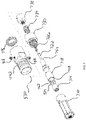
- the tool 510 for installing a blind fastener such as the blind fastener 10 ( FIGS. 1-4 ) is illustrated.
- the tool 510 and its operation can be similar to the tools of co-pending and commonly owned U.S. Patent Application No. 16/203,535 ( U.S. Pub. No. 2019/0160520 , the entire disclosure of which is incorporated herein by reference) and/or International Application No. PCT/US2020/047946 (filed August 26, 2020 , the entire disclosure of which is incorporated herein by reference), except as otherwise shown or described herein.
- the tool 510 includes a nose 514 and a driver 518 drivingly coupled to the nose 514.
- the driver 518 is an electric hand-held nut-runner.
- the driver 518 can be any suitable type of drive mechanism configured to drive the nose 514, such as a pneumatic drive mechanism or an end-effector of a robotic arm for example.
- the driver 518 includes a housing 522 and a drive shaft 526.
- the drive shaft 526 is rotatable relative to the housing 522 about an axis 530 and receives input torque from a motor (not specifically shown) of the driver 518.
- the nose 514 includes a forward nose assembly 532 and a rear nose portion 534 (also referred to herein as a base).
- the rear nose portion 534 is non-rotatably coupled to the housing 522.
- the rear nose portion 534 can include a generally cylindrical body 538 that defines a bore 540 disposed about the axis 530 and configured to receive the drive shaft 526 therein.
- the bore 540 of the rear nose portion 534 can also receive a cylindrical portion 542 of the housing 522 and the rear nose portion 534 can be non-rotatably coupled to the housing 522 by one or more set screws 546 that extend through the rear nose portion 534 and engage the cylindrical portion 542 of the housing 522, though other configurations can be used to fix the rear nose portion 534 to the housing 522.
- the rear nose portion 534 also includes one or more stop members 550.
- the stop members 550 are fixed to the cylindrical body 538 and extend radially inward within the bore 540, though other configurations can be used such as extending axially from the housing 522 for example.
- the forward nose assembly 532 includes a collet 710, a roller clutch or socket assembly 714, a drive member 718 (also referred to herein as a drive body), an ejector pin 722, a first spring 726, an annular body 730 (also referred to herein as an output member), a second spring 734, an input member 738, an outer sleeve 742, and a third spring 746.
- the input member 738 is coaxial with the axis 530 and coupled to the drive shaft 526 for common rotation.
- the end 542 ( FIG. 5 ) of the drive shaft 526 has a predetermined shape (e.g., square or hex for example) that mates with a mating predetermined shaped cavity (not specifically shown) defined by the input member 738, though other configurations can be used.
- the drive member 718 is disposed about the axis 530 and a rearward end 754 of the drive member 718 is coupled to the input member 738 for common rotation about the axis 530.
- the input member 738 is threadably engaged with the drive member 718, though other configurations can be used.
- a forward end 758 of the drive member 718 defines a bore 762.
- the drive member 718 also includes a mode clutch input 1110 disposed between opposite axial ends 754, 758.
- the mode clutch input 1110 includes a plurality of flat surfaces 1114 disposed about the axis 530. In the example provided, the flat surfaces 1114 form a generally hexagonal shape about the axis 530, though other configurations can be used.
- the mode clutch input 1110 also defines angular or helical lead-in ramps 1118 that angle proximate the forward side of each point of the hex shape (i.e., the junction of the flat surfaces 1114), downward toward a cylindrical surface 1122. These lead-in ramps 1118 can aid in rapid engagement of the mode clutch input 1110 with a mating socket or mode clutch output 1126 defined by a forward end of the annular body 730 when not perfectly rotationally aligned.
- the mode clutch output 1126 is a twelve-point star shape configured to mate with the hexagonal shape of the flat surfaces 1114, though other configurations can be used.
- the second spring 734 can be disposed about the drive member 718 and can bias the annular body 730 forward relative to the drive member 718 into engagement with the mode clutch input 1110 to act as a mode clutch.
- a plurality of stop members 1130 also extend axially from a rear end of the annular body 730.
- the stop members 1130 define a shoulder 1134 configured to engage the stop members 550 and act as a clutch.
- the stop members 1130 also include a ramp surface 1138 such that rotation of the annular body 730 in one direction can be inhibited by the shoulder 1134 engaging the stop member 550 while rotation of the annular body 730 in the opposite direction can be permitted by the ramp surface 1138 sliding along the stop member 550 and axially translating the annular body 730.
- the socket assembly 714 includes a socket housing 610 and a plurality of rollers 614.
- the socket housing 610 is coupled to the drive member 718 for common rotation about the axis 530.
- the socket housing 610 is press fit into the bore 762 of the drive member 718, though other configurations can be used.
- the socket housing 610 defines a bore 910 concentric with the axis 530.
- the rollers 614 are spaced circumferentially about the axis and coupled to the socket housing 610 for common rotation about the axis 530.
- a portion of each roller 614 extends into the bore 910 such that a rounded outer surface of each roller is configured to engage the cylindrical surface 156 ( FIGS. 1-3 ) of the bolt 14 ( FIGS. 1-3 ).
- Each roller is rotatable relative to the socket housing 610 about a corresponding axis of that roller 614 that is parallel to the axis 530.
- each roller 614 is a cylindrical body disposed longitudinally parallel to the axis 530. The rollers 614 permit the first tool engagement portion 150 ( FIGS.
- the ejector pin 722 can be disposed concentrically within a bore 918 of the drive member 718 that is concentric with and open to the bore 762.
- the first spring 726 can be disposed within the bore 918 axially between the input member 738 and the ejector pin 722 and configured to bias the ejector pin 722 forward in the bore 918.
- a forward end 922 of the ejector pin 722 can extend into the bore 910 of the socket housing 610.
- a spacer 924 is disposed within the drive member 718 and blocks a rear end 926 of the ejector pin 722 from exiting the bore 918.
- the collet 710 includes a collet sleeve 1010 and a plurality of fingers or prongs 1014.
- the collet sleeve 1010 is disposed about the axis 530.
- the collet sleeve 1010 includes a pair of cam slots 1018 (one of which is shown in FIG. 10 ) through an outer cylindrical surface 1022 of the collet sleeve 1010.
- the cam slot 1018 extends longitudinally at an angle relative to the axis 530.
- Each prong 1014 extends from a forward end of the collet sleeve 1010.
- a forward end of each prong 1014 includes a jaw 1026 that extends radially inward.
- the jaws 1026 cooperate to define an aperture 1030 that can include a plurality of grip features 1034 (e.g., splines) configured to mate with the second tool engagement portion 266 ( FIGS. 1-3 ) of the nut 18.
- the collet sleeve 1010 is coupled to the forward end of the annular body 730 for common rotation about the axis 530.
- the collet sleeve 1010 is threadably coupled to the annular body 730 though other configurations can be used.
- Each prong 1014 includes a ramp surface 810 that narrows radially inward in the rearward direction.
- the ramp surfaces 810 are proximate the jaws 1026 and at the junction of the jaws 1026 and the prongs 1014.
- the outer sleeve 742 is disposed about the collet 710.
- the outer sleeve 742 includes a mating ramp surface 814 that is configured to slide along the ramp surfaces 810 of the prongs 1014.
- the outer sleeve 742 is axially slidable relative to the collet 710 such that when the outer sleeve 742 is in a forward position, the mating ramp surface 814 presses radially inward on the ramp surfaces 810 to press the jaws 1026 radially inward relative to when the outer sleeve 742 is in a retracted or rearward position.
- the third spring 746 biases the outer sleeve 742 toward the forward position.
- follower lugs 818 or (e.g., set screws) can extend radially inward from the outer sleeve 742 into the cam slots 1018.
- the follower lugs 818 are configured to ride along the cam slots 1018 such that when the collet 710 rotates about the axis 530, the outer sleeve 742 rotates therewith but applying a rotational drag force on the outer sleeve 742 can cause the follower lugs 818 to ride rearward in the cam slots 1018 to move the outer sleeve 742 axially rearward.
- the rotational drag may be caused by an operator.
- the tool 510 may optionally include a rotational brake 554 ( FIG. 5 ) to cause the rotational drag.
- the rotational brake 554 is located in the rear nose portion 534 ( FIG. 5 ), though other configurations can be used.
- the blind fastener 10 is loaded into the nose 514 of the tool such that the first tool engagement portion 150 is received in the socket assembly 714 and the second tool engagement portion 266 is gripped by the jaws 1026.
- the blind fastener 10 is inserted into the workpieces 26, 30 either before loading into the tool 510 or after.
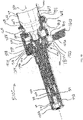
- the tool 510 is then pressed forward until in the position shown in FIG. 14 . Pressing the tool 510 causes the collet 710 to move rearward relative to the rear nose portion 534 so that the stop members 1130 engage the stop members 550 to inhibit rotation of the collet 710.
- the outer sleeve 742 remains forward relative to the collet 710 so the jaws 1026 continue to grip the second tool engagement portion 266.
- the drive member 718 is forward relative to the collet 710 such that the mode clutch input 1110 is not engaged with the mode clutch output 1126.
- the driver 518 is then operated to rotate the drive member 718 to rotate the bolt 14.
- the bolt 14 is rotated until the bulb 410 ( FIG. 4 ) is formed and then the lug 118 breaks off.
- the tool 510 can be slightly retracted so that the tool is generally in the position shown in FIG. 15 .
- the outer sleeve 742 is in the forward position so that the jaws 1026 continue to grip the second tool engagement portion 266.
- the collet 710 is in the forward position such that the annular body 730 is not engaged with the stop members 550.
- the drive member 718 is in the rearward position such that it is engaged for rotation with the annular body 730.
- the driver 518 is operated so that the drive member 718 and the collet 710 rotate until the handling member 218 breaks off.
- the second tool engagement portion 266 is still gripped by the jaws 1026 and the lug 118 is retained in the tool 510 by the handling member 218.
- the tool 510 can then be moved to a location away from the workpieces 26, 30 and the outer sleeve 742 can be moved rearward (either directly or via the rotational brake 554 schematically shown in FIG. 5 ). This permits the jaws 1026 to expand radially outward, releasing the handling member 218.
- the ejector pin 722 is pressed forward by the first spring 726 and ejects the lug 118 from the tool 510, which can also eject the handling member 218 from the tool 510.
- the third spring 746 is stiffer than the second spring 734 such that when the outer sleeve 742 is pulled back, the stop members 1130 engage the stop members 550 before the collet 710 opens.
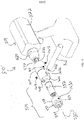
- the driver 518 also includes a shroud 1610 and a reaction bar 1612, also referred to herein as a handle.
- the shroud 1610 is a generally cylindrical body disposed about the axis 530 and fixed to the housing 522.
- the shroud 1610 defines a pair of threaded apertures 1614 (one of which is visible in FIG.
- the shroud 1610 defines a central bore 1622 concentric about the axis 530 and extending axially through the shroud 1610 and a slot 1626 extending through a sidewall of the shroud 1610 and open to the central bore 1622.
- the rear nose portion 534 is slidably received in the central bore 1622 and defines a threaded bore 1630 through a side wall of the cylindrical body 538 that aligns with the slot 1626.
- An end 1632 of the reaction bar 1612 extends through the slot 1626 and threadably engages the bore 1630.
- the slot 1626 inhibits rotation of the reaction bar 1612 but permits axial translation within the slot 1626.
- the shroud 1610 can optionally define a second slot 1628 on the opposite side and the cylindrical body 538 can define a second threaded bore (not visible in FIG. 16 ) on the opposite side to permit the reaction bar 1612 to be switched to the other side.
- the cylindrical body 538 defines a shoulder 1710 and the outer sleeve 742 defines a lip 1714 configured to engage the shoulder 1710 to inhibit the outer sleeve 742 from translating axially outward from the cylindrical body 538 beyond the position shown in FIG. 17 .
- the shoulder 1710 and lip 1714 extend circumferentially about the axis 530, though other configurations can be used. In the position shown in FIG.
- a rear end 1718 of the cylindrical body 538 is spaced apart from a shoulder 1722 of the shroud 1610 such that the reaction bar 1612 can be pulled axially backwards (i.e., toward the housing 522) in the slot 1626 to translate the cylindrical body 538 and thus the outer sleeve 742 backwards.
- an operator can release the collet 710 by pulling the reaction bar 1612.
- the stop members 550 (one of which is shown in FIG. 17 ) extend radially inward from the shroud 1610, though other configurations can be used.
- FIGS. 18-25 a tool 510" of a third configuration is illustrated.
- the tool 510" is similar to the tool 510 ( FIGS. 5-15 ) and 510' ( FIGS. 16 and 17 ) except as otherwise shown or described herein. Accordingly, similar features are denoted by similar reference numerals and only differences are described in detail herein.
- the shroud 1610 does not define the slot 1626.
- the stop members 550 (one of which is shown in FIG. 19 ) extends radially inward from the shroud 1610.
- the rear end 1718 of the cylindrical body 538 is disposed about the shroud 1610 and is slidable along an outer surface 1912 of the shroud 1610 axially and rotationally with reference to the axis 530.
- the rear nose portion 534 also includes an outer shroud 1810 disposed concentrically about the cylindrical body 538.
- the outer shroud 1810 defines a rear facing shoulder 2010 (labeled in FIG. 20 ) configured to abut a forward facing lip 2014 (labeled in FIG. 20 ) of the cylindrical body 538.
- the cylindrical body 538 is rotatable about the axis 530 relative to the outer shroud 1810.
- the outer shroud 1810 defines a first slot 1814 extending radially through one side of the outer shroud 1810.
- the first slot 1814 extends longitudinally in the circumferential direction about the axis 530.
- the outer shroud 1810 also defines a second slot 1818 extending radially through one side of the outer shroud 1810.
- the first and second slots 1814 and 1818 are on the same side of the outer shroud 1810, though other configurations can be used.
- the second slot 1818 is axially rearward of the first slot 1814 and extends longitudinally in the axial direction.
- the outer shroud 1810 can also define a bore 2114 extending through a side of the outer shroud 1810 and aligned with a bore 1918 defined tangentially in a side of the cylindrical body 538.
- a spring 1914 is disposed within the bore 1918 and a plug 2110 is disposed within the bore 2114 to maintain the spring in the bore 1918.
- the plug 2110 is threadably engaged with the bore 2114, though other configurations can be used.
- the spring 1914 is configured to bias the cylindrical body 538 rotationally relative to the outer shroud 1810 in the rotational direction 2120.
- the end 1632 of the reaction bar 1612 extends through the first slot 1814 and is coupled to the cylindrical body 538.
- the end 1632 is threaded and received in a threaded bore 1922 defined by the cylindrical body 538, though other configurations can be used.
- the cylindrical body 538 defines an aperture 1934 that extends radially through a side of the cylindrical body 538.
- the aperture 1934 is delimited in the rearward direction by a rear surface 2218.
- a first region of the aperture 1934 is delimited in the forward direction by a first forward surface 2210 and a second region of the aperture 1934 is delimited in the forward direction by a second forward surface 2214.
- the first forward surface 2210 is further in the axial direction from the rear surface 2218 than the second forward surface 2214.
- the first forward surface 2210 is further in the rotational direction 2120 than the second forward surface 2214.
- the aperture 2210 generally aligns with the slot 1818.
- One of the set screws 1618 extends through the slot 1818 and through the aperture 2210 and is threadably engaged with the threaded aperture 1614 to act as a limit pin that limits movement of the cylindrical body 538 and outer shroud 1810 relative to the shroud 1610.
- the cylindrical body 538 may also define a circumferential groove 1912 that is open radially inward.
- a retainer 1910 e.g., a resilient snap ring or C-clip
- a retainer 1910 is received in the groove 1912 and extends radially inward therefrom to block the lip 1714 of the outer sleeve 742 to inhibit relative axial motion between the outer sleeve 742 and the cylindrical body 538.
- the second spring 734 can the annular body 730 forward relative to the drive member 718 and into the position in which the mode clutch input 1110 is engaged.
- the third spring 746 biases the outer sleeve 742 into the forward position. Since the cylindrical body 538 is coupled to the outer sleeve 742 for axial movement therewith via the retainer 1910, the cylindrical body 538 and the reaction bar 1612 are also in a forward position relative to the shroud 1610. In this forward position, the set screw 1618 engages the rear surface 2218 (labeled in FIG. 22 ) of the aperture 1934 and a rear surface 2222 (labeled in FIG. 22 ) of the slot 1818.
- spring 1914 biases the cylindrical body in the rotational direction 2120 (labeled in FIGS. 21 and 22 ) so that the reaction bar 1612 is toward the bottom of the first slot 1814.
- the set screw 1618 can engage a top surface 2226 (labeled in FIG. 22 ).
- the reaction bar 1612 is rotated in the rotational direction opposite direction 2120 (labeled in FIGS. 21 and 22 ) until the set screw 1618 engages a bottom surface 2230 ( FIG. 22 ) of the aperture 1934 and is then translated rearward until the set screw 1618 engages the first forward surface 2210.
- the reaction bar 1612 can be located toward a top of the first slot 1814.
- the set screw 1618 may engage a front surface 2234 (labeled in FIG. 22 ) of the slot 1818.
- the outer sleeve 742 is rearward and the jaws 1026 are expanded.
- the tool 510" is then moved forward until the first tool engagement portion 150 (labeled in FIG. 2 ) and the second tool engagement portion 266 (labeled in FIG. 2 ) are received in the tool 510".
- blind fastener 10 is illustrated in FIG. 23 as already positioned in the workpieces 26, 30, the blind fastener 10 may alternatively be first inserted into the tool 510" with the tool 510" in the position shown in FIG. 23 and then retained in the tool 510" by moving the reaction bar 1612 to the position shown in FIGS. 24 and 25 and described below.
- the reaction bar 1612 then translates axially to the position shown in FIGS. 24 and 25 and then rotates in the direction 2120 (labeled in FIG. 22 ) back toward the bottom of the slot 1814 so that the set screw 1618 engages the forward surface 2214 ( FIG. 22 ) of the aperture 1924 ( FIG. 22 ).
- the first tool engagement portion 150 (labeled in FIG. 2 ) and the second tool engagement portion 266 (labeled in FIG. 2 ) are engaged by the socket assembly 714 and the jaws 1026, respectively.
- the mode clutch 1110 is disengaged so that the socket 714 can rotate relative to the jaws 1026.
- the stop members 1130 engage the stop members 550 to inhibit rotation of the jaws 1026.
- the socket 714 can be rotated by the driver 518 ( FIG. 18 ) until the first tool engagement portion 150 (labeled in FIG. 2 ) breaks off.
- the driver 518 can be translated rearward slightly until the set screw 1618 is again in the position shown in FIGS. 18-21 .
- the stop members 1130 are disengaged from the stop members 550, the mode clutch 1110 is engaged so that the socket 714 rotates with the jaws 1026, and the outer sleeve 742 remains forward to maintain the jaws 1026 in gripping position with the second tool engagement portion 266 ( FIG. 2 ).
- the driver 518 can be operated to rotate the second tool engagement portion 266 ( FIG. 2 ) until it breaks off.
- the tool 510" can then be moved away from the installed blind fastener 10 and panels 26, 30 to release the broken off first and second tool engagement portions 150, 266.
- the reaction bar 1612 is moved again to the position shown in FIG. 23 and the spring 726 pushes the ejector pin 722 to eject the broken off first and second tool engagement portions 150, 266.
- the tool 510" can attach the blind fastener 10 to the workpieces 26, 30, retain the broken off components, and release them at to safe location to avoid the broken off components from impacting or damaging the workpieces 26, 30 or other components (not shown) nearby.
- any one of the tools 510, 510', or 510" can be used with a driver 518 that can optionally be an electric smart driver, capable of tracking and storing installation data, which can be integrated into a smart tool communication system and provide installation data for every part installed.
- a driver 518 can optionally be an electric smart driver, capable of tracking and storing installation data, which can be integrated into a smart tool communication system and provide installation data for every part installed.
- a blind fastener for connecting a plurality of workpieces comprises:
- an end surface of the bolt head may be flush with or recessed from an end surface of the nut head when the bolt is fully threaded into the nut.
- the first frangible portion may be configured to break off from the bolt head such that an end surface of the bolt head is flush with or recessed from a front surface of the plurality of workpieces
- the second frangible portion may be configured to break off from the nut head such that an end surface of the nut head is flush with or recessed from the front surface
- the lug may taper radially inward from the cylindrical outer surface to a terminal end portion of the bolt.
- the handling member may taper radially inward from the second tool engagement portion to a terminal end portion of the nut.
- the second frangible portion may be entirely radially inward of an outermost perimeter of the nut head.
- the handling member may define a bore having a diameter equal to an outermost diameter of the recess.
- a radially outermost surface of the lug may be disposed radially outward of a bore defined by the handling member, the first frangible portion extending through the bore.
- the handling member may be entirely radially outward of the first tool engagement portion.
- the lug may taper radially inward from the cylindrical outer surface to the first frangible portion.
- the blind fastener may consist of two pieces when in a pre-installed condition, the bolt being a first one of the two pieces and the nut being a second one of the two pieces.
- the second frangible portion may define a break-neck that extends around a full circumference of the nut.
- the first frangible portion may include a break-neck that extends around a full circumference of the bolt.
- the bolt may be an aluminum material and the sleeve may be a titanium material.
- the bolt may be a 6-4 titanium alloy material and the sleeve may be an unalloyed commercially pure titanium material.
- the phrase at least one of A, B, and C should be construed to mean a logical (A OR B OR C), using a non-exclusive logical OR, and should not be construed to mean "at least one of A, at least one of B, and at least one of C.
Landscapes
- Engineering & Computer Science (AREA)
- Mechanical Engineering (AREA)
- General Engineering & Computer Science (AREA)
- Gripping On Spindles (AREA)
- Dowels (AREA)
- Details Of Spanners, Wrenches, And Screw Drivers And Accessories (AREA)
Priority Applications (1)
| Application Number | Priority Date | Filing Date | Title |
|---|---|---|---|
| EP25174274.8A EP4575242A3 (de) | 2020-12-17 | 2021-12-17 | Zweiteiliger blindbefestiger und installationswerkzeug |
Applications Claiming Priority (1)
| Application Number | Priority Date | Filing Date | Title |
|---|---|---|---|
| US202063126799P | 2020-12-17 | 2020-12-17 |
Related Child Applications (2)
| Application Number | Title | Priority Date | Filing Date |
|---|---|---|---|
| EP25174274.8A Division EP4575242A3 (de) | 2020-12-17 | 2021-12-17 | Zweiteiliger blindbefestiger und installationswerkzeug |
| EP25174274.8A Division-Into EP4575242A3 (de) | 2020-12-17 | 2021-12-17 | Zweiteiliger blindbefestiger und installationswerkzeug |
Publications (2)
| Publication Number | Publication Date |
|---|---|
| EP4015151A1 true EP4015151A1 (de) | 2022-06-22 |
| EP4015151B1 EP4015151B1 (de) | 2025-06-18 |
Family
ID=78957179
Family Applications (2)
| Application Number | Title | Priority Date | Filing Date |
|---|---|---|---|
| EP21215522.0A Active EP4015151B1 (de) | 2020-12-17 | 2021-12-17 | Zweiteiliger blindbefestiger und installationswerkzeug |
| EP25174274.8A Pending EP4575242A3 (de) | 2020-12-17 | 2021-12-17 | Zweiteiliger blindbefestiger und installationswerkzeug |
Family Applications After (1)
| Application Number | Title | Priority Date | Filing Date |
|---|---|---|---|
| EP25174274.8A Pending EP4575242A3 (de) | 2020-12-17 | 2021-12-17 | Zweiteiliger blindbefestiger und installationswerkzeug |
Country Status (7)
| Country | Link |
|---|---|
| US (3) | US20230069811A9 (de) |
| EP (2) | EP4015151B1 (de) |
| CN (1) | CN114643552A (de) |
| BR (1) | BR102021025606A8 (de) |
| CA (1) | CA3142366C (de) |
| ES (1) | ES3037075T3 (de) |
| MX (2) | MX2025010160A (de) |
Families Citing this family (1)
| Publication number | Priority date | Publication date | Assignee | Title |
|---|---|---|---|---|
| USD1121426S1 (en) * | 2020-12-17 | 2026-04-07 | Sps Technologies, Llc | Blind fastener |
Citations (3)
| Publication number | Priority date | Publication date | Assignee | Title |
|---|---|---|---|---|
| US9669457B2 (en) * | 2014-01-14 | 2017-06-06 | Lisi Aerospace | Rivet for blind fasteners, associated setting tool and method for setting such a rivet |
| US20190160520A1 (en) | 2017-11-28 | 2019-05-30 | Sps Technologies, Llc | Automatic double-action fastener installation tool |
| US20190162217A1 (en) | 2017-11-27 | 2019-05-30 | Sps Technologies, Llc | Two-piece blind fastener |
Family Cites Families (20)
| Publication number | Priority date | Publication date | Assignee | Title |
|---|---|---|---|---|
| US3357094A (en) * | 1964-12-04 | 1967-12-12 | Nat Screw & Mfg Company | Blind fastener |
| GB1135538A (en) * | 1967-04-28 | 1968-12-04 | Sweeney Mfg Co B K | Bolt tightening tool |
| DE4302083A1 (de) * | 1993-01-19 | 1994-07-21 | Black & Decker Inc | Kraftgetriebenes Werkzeug, insbesondere Elektrowerkzeug |
| US7475619B2 (en) * | 2005-04-22 | 2009-01-13 | The Stanley Works | Over torque proof socket |
| US9212678B2 (en) * | 2011-04-14 | 2015-12-15 | John D. Pratt | Fastener and method of installing same |
| EP2758677A1 (de) * | 2011-09-19 | 2014-07-30 | Monogram Aerospace Fasteners, Inc. | Blindbefestiger mit abnehmbarer schraubenschlüsselvorrichtung und verfahren zur entfernung der schraubenschlüsselvorrichtung |
| US9284971B2 (en) * | 2012-04-04 | 2016-03-15 | John D. Pratt | Fastener and method of installing same |
| US9903403B2 (en) * | 2012-04-04 | 2018-02-27 | John D. Pratt | Fastener and method of installing same |
| US8979453B2 (en) * | 2012-04-17 | 2015-03-17 | Alcoa Inc. | Blind fastener |
| US9149873B2 (en) * | 2012-06-05 | 2015-10-06 | Robert Bosch Gmbh | Collet retention mechanism for a rotary tool |
| US9593706B2 (en) * | 2012-11-11 | 2017-03-14 | The Boeing Company | Structural blind fastener and method of installation |
| CN203516322U (zh) * | 2013-07-02 | 2014-04-02 | J·D·普拉特 | 紧固件 |
| CN104308790B (zh) * | 2014-09-29 | 2015-08-26 | 洪劲松 | 铆螺母电动工具 |
| FR3037369B1 (fr) * | 2015-06-11 | 2017-07-21 | Lisi Aerospace | Fixation installee d'un seul cote a douille deformable |
| FR3053745B1 (fr) * | 2016-07-06 | 2019-05-17 | Lisi Aerospace | Rivet de fixation aveugle avec fut epaule et procede d'installation associe |
| US10774863B2 (en) * | 2018-06-18 | 2020-09-15 | The Boeing Company | Blind fastener system with electromagnetic effects-protective coating |
| FR3085448B1 (fr) * | 2018-09-04 | 2020-11-27 | Lisi Aerospace | Vis avec gorge de rupture, fixation comprenant une telle vis, assemblage et procede d'installation associes |
| BR112022003770A2 (pt) * | 2019-08-26 | 2022-05-31 | Sps Tech Llc | Fecho cego de duas peças e ferramenta de instalação |
| US11959504B2 (en) * | 2020-07-24 | 2024-04-16 | Howmet Aerospace Inc. | Self-forming thread blind fastener |
| EP4406676A3 (de) * | 2020-12-08 | 2024-10-02 | The Boeing Company | Verfahren und werkzeug zum setzen eines befestigungselements |
-
2021
- 2021-12-15 CA CA3142366A patent/CA3142366C/en active Active
- 2021-12-15 US US17/551,796 patent/US20230069811A9/en not_active Abandoned
- 2021-12-17 EP EP21215522.0A patent/EP4015151B1/de active Active
- 2021-12-17 MX MX2025010160A patent/MX2025010160A/es unknown
- 2021-12-17 EP EP25174274.8A patent/EP4575242A3/de active Pending
- 2021-12-17 CN CN202111548871.3A patent/CN114643552A/zh active Pending
- 2021-12-17 BR BR102021025606A patent/BR102021025606A8/pt active IP Right Grant
- 2021-12-17 MX MX2021016118A patent/MX2021016118A/es unknown
- 2021-12-17 ES ES21215522T patent/ES3037075T3/es active Active
-
2025
- 2025-03-10 US US19/074,518 patent/US20250205774A1/en active Pending
- 2025-03-11 US US19/076,506 patent/US20250205775A1/en active Pending
Patent Citations (3)
| Publication number | Priority date | Publication date | Assignee | Title |
|---|---|---|---|---|
| US9669457B2 (en) * | 2014-01-14 | 2017-06-06 | Lisi Aerospace | Rivet for blind fasteners, associated setting tool and method for setting such a rivet |
| US20190162217A1 (en) | 2017-11-27 | 2019-05-30 | Sps Technologies, Llc | Two-piece blind fastener |
| US20190160520A1 (en) | 2017-11-28 | 2019-05-30 | Sps Technologies, Llc | Automatic double-action fastener installation tool |
Also Published As
| Publication number | Publication date |
|---|---|
| BR102021025606A8 (pt) | 2024-02-15 |
| MX2021016118A (es) | 2022-06-20 |
| CA3142366A1 (en) | 2022-06-17 |
| US20230069811A9 (en) | 2023-03-02 |
| CA3142366C (en) | 2023-11-07 |
| ES3037075T3 (en) | 2025-09-26 |
| EP4575242A2 (de) | 2025-06-25 |
| BR102021025606A2 (pt) | 2022-06-28 |
| US20220105557A1 (en) | 2022-04-07 |
| US20250205774A1 (en) | 2025-06-26 |
| MX2025010160A (es) | 2025-10-01 |
| US20250205775A1 (en) | 2025-06-26 |
| EP4015151B1 (de) | 2025-06-18 |
| CN114643552A (zh) | 2022-06-21 |
| EP4575242A3 (de) | 2025-08-13 |
Similar Documents
| Publication | Publication Date | Title |
|---|---|---|
| EP4375018B1 (de) | Zweiteiliger blindanreisser und installationswerkzeug | |
| US10974310B2 (en) | Automatic double-action fastener installation tool | |
| US11143226B2 (en) | Two-piece blind fastener | |
| EP1635994B1 (de) | Blindniet und nasenanordnung zur installation des blindniets | |
| US20250205775A1 (en) | Two-piece blind fastener installation tool | |
| EP0198105A1 (de) | Ein sicher lösbares, stiftdrahtförmiges Spannmittel für automatisches Einsteck- und Ausziehwerk | |
| US20010006014A1 (en) | Combination driving tool | |
| US4979279A (en) | Fastener installation tool apparatus | |
| EP0216980A1 (de) | Blindbefestiger mit Hutmutter sowie Verfahren zur Montage desselben | |
| US20260124683A1 (en) | Chuck with quick connect spindle interface | |
| WO2024234217A1 (en) | Chuck with quick connect spindle interface | |
| CN214263908U (zh) | 一种便于车削法兰盲板的车床 | |
| EP1952923A1 (de) | Spannzangenfutter für Maschinenwerkzeuge |
Legal Events
| Date | Code | Title | Description |
|---|---|---|---|
| PUAI | Public reference made under article 153(3) epc to a published international application that has entered the european phase |
Free format text: ORIGINAL CODE: 0009012 |
|
| STAA | Information on the status of an ep patent application or granted ep patent |
Free format text: STATUS: THE APPLICATION HAS BEEN PUBLISHED |
|
| AK | Designated contracting states |
Kind code of ref document: A1 Designated state(s): AL AT BE BG CH CY CZ DE DK EE ES FI FR GB GR HR HU IE IS IT LI LT LU LV MC MK MT NL NO PL PT RO RS SE SI SK SM TR |
|
| STAA | Information on the status of an ep patent application or granted ep patent |
Free format text: STATUS: REQUEST FOR EXAMINATION WAS MADE |
|
| 17P | Request for examination filed |
Effective date: 20221028 |
|
| RBV | Designated contracting states (corrected) |
Designated state(s): AL AT BE BG CH CY CZ DE DK EE ES FI FR GB GR HR HU IE IS IT LI LT LU LV MC MK MT NL NO PL PT RO RS SE SI SK SM TR |
|
| GRAP | Despatch of communication of intention to grant a patent |
Free format text: ORIGINAL CODE: EPIDOSNIGR1 |
|
| STAA | Information on the status of an ep patent application or granted ep patent |
Free format text: STATUS: GRANT OF PATENT IS INTENDED |
|
| INTG | Intention to grant announced |
Effective date: 20240607 |
|
| GRAJ | Information related to disapproval of communication of intention to grant by the applicant or resumption of examination proceedings by the epo deleted |
Free format text: ORIGINAL CODE: EPIDOSDIGR1 |
|
| STAA | Information on the status of an ep patent application or granted ep patent |
Free format text: STATUS: REQUEST FOR EXAMINATION WAS MADE |
|
| GRAP | Despatch of communication of intention to grant a patent |
Free format text: ORIGINAL CODE: EPIDOSNIGR1 |
|
| STAA | Information on the status of an ep patent application or granted ep patent |
Free format text: STATUS: GRANT OF PATENT IS INTENDED |
|
| INTC | Intention to grant announced (deleted) | ||
| INTG | Intention to grant announced |
Effective date: 20250120 |
|
| GRAS | Grant fee paid |
Free format text: ORIGINAL CODE: EPIDOSNIGR3 |
|
| GRAA | (expected) grant |
Free format text: ORIGINAL CODE: 0009210 |
|
| STAA | Information on the status of an ep patent application or granted ep patent |
Free format text: STATUS: THE PATENT HAS BEEN GRANTED |
|
| P01 | Opt-out of the competence of the unified patent court (upc) registered |
Free format text: CASE NUMBER: APP_19802/2025 Effective date: 20250424 |
|
| AK | Designated contracting states |
Kind code of ref document: B1 Designated state(s): AL AT BE BG CH CY CZ DE DK EE ES FI FR GB GR HR HU IE IS IT LI LT LU LV MC MK MT NL NO PL PT RO RS SE SI SK SM TR |
|
| REG | Reference to a national code |
Ref country code: GB Ref legal event code: FG4D |
|
| REG | Reference to a national code |
Ref country code: CH Ref legal event code: EP |
|
| REG | Reference to a national code |
Ref country code: DE Ref legal event code: R096 Ref document number: 602021032406 Country of ref document: DE |
|
| REG | Reference to a national code |
Ref country code: CH Ref legal event code: EP |
|
| REG | Reference to a national code |
Ref country code: IE Ref legal event code: FG4D |
|
| REG | Reference to a national code |
Ref country code: NL Ref legal event code: FP |
|
| REG | Reference to a national code |
Ref country code: ES Ref legal event code: FG2A Ref document number: 3037075 Country of ref document: ES Kind code of ref document: T3 Effective date: 20250926 |
|
| PG25 | Lapsed in a contracting state [announced via postgrant information from national office to epo] |
Ref country code: FI Free format text: LAPSE BECAUSE OF FAILURE TO SUBMIT A TRANSLATION OF THE DESCRIPTION OR TO PAY THE FEE WITHIN THE PRESCRIBED TIME-LIMIT Effective date: 20250618 |
|
| REG | Reference to a national code |
Ref country code: LT Ref legal event code: MG9D |
|
| PG25 | Lapsed in a contracting state [announced via postgrant information from national office to epo] |
Ref country code: GR Free format text: LAPSE BECAUSE OF FAILURE TO SUBMIT A TRANSLATION OF THE DESCRIPTION OR TO PAY THE FEE WITHIN THE PRESCRIBED TIME-LIMIT Effective date: 20250919 Ref country code: NO Free format text: LAPSE BECAUSE OF FAILURE TO SUBMIT A TRANSLATION OF THE DESCRIPTION OR TO PAY THE FEE WITHIN THE PRESCRIBED TIME-LIMIT Effective date: 20250918 |
|
| PG25 | Lapsed in a contracting state [announced via postgrant information from national office to epo] |
Ref country code: BG Free format text: LAPSE BECAUSE OF FAILURE TO SUBMIT A TRANSLATION OF THE DESCRIPTION OR TO PAY THE FEE WITHIN THE PRESCRIBED TIME-LIMIT Effective date: 20250618 |
|
| PG25 | Lapsed in a contracting state [announced via postgrant information from national office to epo] |
Ref country code: HR Free format text: LAPSE BECAUSE OF FAILURE TO SUBMIT A TRANSLATION OF THE DESCRIPTION OR TO PAY THE FEE WITHIN THE PRESCRIBED TIME-LIMIT Effective date: 20250618 |
|
| PG25 | Lapsed in a contracting state [announced via postgrant information from national office to epo] |
Ref country code: RS Free format text: LAPSE BECAUSE OF FAILURE TO SUBMIT A TRANSLATION OF THE DESCRIPTION OR TO PAY THE FEE WITHIN THE PRESCRIBED TIME-LIMIT Effective date: 20250918 |
|
| PG25 | Lapsed in a contracting state [announced via postgrant information from national office to epo] |
Ref country code: LV Free format text: LAPSE BECAUSE OF FAILURE TO SUBMIT A TRANSLATION OF THE DESCRIPTION OR TO PAY THE FEE WITHIN THE PRESCRIBED TIME-LIMIT Effective date: 20250618 |
|
| PG25 | Lapsed in a contracting state [announced via postgrant information from national office to epo] |
Ref country code: PT Free format text: LAPSE BECAUSE OF FAILURE TO SUBMIT A TRANSLATION OF THE DESCRIPTION OR TO PAY THE FEE WITHIN THE PRESCRIBED TIME-LIMIT Effective date: 20251020 |
|
| REG | Reference to a national code |
Ref country code: AT Ref legal event code: MK05 Ref document number: 1803792 Country of ref document: AT Kind code of ref document: T Effective date: 20250618 |
|
| PG25 | Lapsed in a contracting state [announced via postgrant information from national office to epo] |
Ref country code: IS Free format text: LAPSE BECAUSE OF FAILURE TO SUBMIT A TRANSLATION OF THE DESCRIPTION OR TO PAY THE FEE WITHIN THE PRESCRIBED TIME-LIMIT Effective date: 20251018 |
|
| PGFP | Annual fee paid to national office [announced via postgrant information from national office to epo] |
Ref country code: GB Payment date: 20251229 Year of fee payment: 5 |
|
| PG25 | Lapsed in a contracting state [announced via postgrant information from national office to epo] |
Ref country code: AT Free format text: LAPSE BECAUSE OF FAILURE TO SUBMIT A TRANSLATION OF THE DESCRIPTION OR TO PAY THE FEE WITHIN THE PRESCRIBED TIME-LIMIT Effective date: 20250618 Ref country code: SM Free format text: LAPSE BECAUSE OF FAILURE TO SUBMIT A TRANSLATION OF THE DESCRIPTION OR TO PAY THE FEE WITHIN THE PRESCRIBED TIME-LIMIT Effective date: 20250618 |
|
| PGFP | Annual fee paid to national office [announced via postgrant information from national office to epo] |
Ref country code: IT Payment date: 20251219 Year of fee payment: 5 |
|
| PGFP | Annual fee paid to national office [announced via postgrant information from national office to epo] |
Ref country code: NL Payment date: 20251226 Year of fee payment: 5 Ref country code: FR Payment date: 20251226 Year of fee payment: 5 |
|
| PG25 | Lapsed in a contracting state [announced via postgrant information from national office to epo] |
Ref country code: CZ Free format text: LAPSE BECAUSE OF FAILURE TO SUBMIT A TRANSLATION OF THE DESCRIPTION OR TO PAY THE FEE WITHIN THE PRESCRIBED TIME-LIMIT Effective date: 20250618 |
|
| PGFP | Annual fee paid to national office [announced via postgrant information from national office to epo] |
Ref country code: IE Payment date: 20251229 Year of fee payment: 5 |
|
| PG25 | Lapsed in a contracting state [announced via postgrant information from national office to epo] |
Ref country code: PL Free format text: LAPSE BECAUSE OF FAILURE TO SUBMIT A TRANSLATION OF THE DESCRIPTION OR TO PAY THE FEE WITHIN THE PRESCRIBED TIME-LIMIT Effective date: 20250618 |
|
| PG25 | Lapsed in a contracting state [announced via postgrant information from national office to epo] |
Ref country code: EE Free format text: LAPSE BECAUSE OF FAILURE TO SUBMIT A TRANSLATION OF THE DESCRIPTION OR TO PAY THE FEE WITHIN THE PRESCRIBED TIME-LIMIT Effective date: 20250618 |
|
| PG25 | Lapsed in a contracting state [announced via postgrant information from national office to epo] |
Ref country code: SK Free format text: LAPSE BECAUSE OF FAILURE TO SUBMIT A TRANSLATION OF THE DESCRIPTION OR TO PAY THE FEE WITHIN THE PRESCRIBED TIME-LIMIT Effective date: 20250618 Ref country code: RO Free format text: LAPSE BECAUSE OF FAILURE TO SUBMIT A TRANSLATION OF THE DESCRIPTION OR TO PAY THE FEE WITHIN THE PRESCRIBED TIME-LIMIT Effective date: 20250618 |
|
| REG | Reference to a national code |
Ref country code: DE Ref legal event code: R097 Ref document number: 602021032406 Country of ref document: DE |
|
| PGFP | Annual fee paid to national office [announced via postgrant information from national office to epo] |
Ref country code: ES Payment date: 20260102 Year of fee payment: 5 |
|
| PG25 | Lapsed in a contracting state [announced via postgrant information from national office to epo] |
Ref country code: DK Free format text: LAPSE BECAUSE OF FAILURE TO SUBMIT A TRANSLATION OF THE DESCRIPTION OR TO PAY THE FEE WITHIN THE PRESCRIBED TIME-LIMIT Effective date: 20250618 |
|
| PGFP | Annual fee paid to national office [announced via postgrant information from national office to epo] |
Ref country code: DE Payment date: 20251229 Year of fee payment: 5 |
|
| PLBE | No opposition filed within time limit |
Free format text: ORIGINAL CODE: 0009261 |
|
| STAA | Information on the status of an ep patent application or granted ep patent |
Free format text: STATUS: NO OPPOSITION FILED WITHIN TIME LIMIT |
|
| REG | Reference to a national code |
Ref country code: CH Ref legal event code: L10 Free format text: ST27 STATUS EVENT CODE: U-0-0-L10-L00 (AS PROVIDED BY THE NATIONAL OFFICE) Effective date: 20260430 |