EP4015159A2 - Appareil et procédé pour effectuer une génération d'images d'objets, une reconnaissance d'objets et un apprentissage d'environnement par un robot mobile - Google Patents
Appareil et procédé pour effectuer une génération d'images d'objets, une reconnaissance d'objets et un apprentissage d'environnement par un robot mobile Download PDFInfo
- Publication number
- EP4015159A2 EP4015159A2 EP20840775.9A EP20840775A EP4015159A2 EP 4015159 A2 EP4015159 A2 EP 4015159A2 EP 20840775 A EP20840775 A EP 20840775A EP 4015159 A2 EP4015159 A2 EP 4015159A2
- Authority
- EP
- European Patent Office
- Prior art keywords
- image
- information
- unit
- environment
- mobile robot
- Prior art date
- Legal status (The legal status is an assumption and is not a legal conclusion. Google has not performed a legal analysis and makes no representation as to the accuracy of the status listed.)
- Granted
Links
Images







Classifications
-
- G—PHYSICS
- G05—CONTROLLING; REGULATING
- G05D—SYSTEMS FOR CONTROLLING OR REGULATING NON-ELECTRIC VARIABLES
- G05D1/00—Control of position, course, altitude or attitude of land, water, air or space vehicles, e.g. using automatic pilots
- G05D1/02—Control of position or course in two dimensions
- G05D1/021—Control of position or course in two dimensions specially adapted to land vehicles
- G05D1/0231—Control of position or course in two dimensions specially adapted to land vehicles using optical position detecting means
- G05D1/0246—Control of position or course in two dimensions specially adapted to land vehicles using optical position detecting means using a video camera in combination with image processing means
- G05D1/0248—Control of position or course in two dimensions specially adapted to land vehicles using optical position detecting means using a video camera in combination with image processing means in combination with a laser
-
- G—PHYSICS
- G06—COMPUTING OR CALCULATING; COUNTING
- G06V—IMAGE OR VIDEO RECOGNITION OR UNDERSTANDING
- G06V20/00—Scenes; Scene-specific elements
- G06V20/50—Context or environment of the image
-
- B—PERFORMING OPERATIONS; TRANSPORTING
- B25—HAND TOOLS; PORTABLE POWER-DRIVEN TOOLS; MANIPULATORS
- B25J—MANIPULATORS; CHAMBERS PROVIDED WITH MANIPULATION DEVICES
- B25J9/00—Program-controlled manipulators
- B25J9/16—Program controls
-
- B—PERFORMING OPERATIONS; TRANSPORTING
- B25—HAND TOOLS; PORTABLE POWER-DRIVEN TOOLS; MANIPULATORS
- B25J—MANIPULATORS; CHAMBERS PROVIDED WITH MANIPULATION DEVICES
- B25J9/00—Program-controlled manipulators
- B25J9/16—Program controls
- B25J9/1628—Program controls characterised by the control loop
- B25J9/163—Program controls characterised by the control loop learning, adaptive, model based, rule based expert control
-
- B—PERFORMING OPERATIONS; TRANSPORTING
- B25—HAND TOOLS; PORTABLE POWER-DRIVEN TOOLS; MANIPULATORS
- B25J—MANIPULATORS; CHAMBERS PROVIDED WITH MANIPULATION DEVICES
- B25J9/00—Program-controlled manipulators
- B25J9/16—Program controls
- B25J9/1656—Program controls characterised by programming, planning systems for manipulators
- B25J9/1664—Program controls characterised by programming, planning systems for manipulators characterised by motion, path, trajectory planning
-
- G—PHYSICS
- G05—CONTROLLING; REGULATING
- G05D—SYSTEMS FOR CONTROLLING OR REGULATING NON-ELECTRIC VARIABLES
- G05D1/00—Control of position, course, altitude or attitude of land, water, air or space vehicles, e.g. using automatic pilots
- G05D1/02—Control of position or course in two dimensions
- G05D1/021—Control of position or course in two dimensions specially adapted to land vehicles
- G05D1/0231—Control of position or course in two dimensions specially adapted to land vehicles using optical position detecting means
- G05D1/0238—Control of position or course in two dimensions specially adapted to land vehicles using optical position detecting means using obstacle or wall sensors
- G05D1/024—Control of position or course in two dimensions specially adapted to land vehicles using optical position detecting means using obstacle or wall sensors in combination with a laser
-
- G—PHYSICS
- G05—CONTROLLING; REGULATING
- G05D—SYSTEMS FOR CONTROLLING OR REGULATING NON-ELECTRIC VARIABLES
- G05D1/00—Control of position, course, altitude or attitude of land, water, air or space vehicles, e.g. using automatic pilots
- G05D1/02—Control of position or course in two dimensions
- G05D1/021—Control of position or course in two dimensions specially adapted to land vehicles
- G05D1/0231—Control of position or course in two dimensions specially adapted to land vehicles using optical position detecting means
- G05D1/0246—Control of position or course in two dimensions specially adapted to land vehicles using optical position detecting means using a video camera in combination with image processing means
-
- G—PHYSICS
- G05—CONTROLLING; REGULATING
- G05D—SYSTEMS FOR CONTROLLING OR REGULATING NON-ELECTRIC VARIABLES
- G05D1/00—Control of position, course, altitude or attitude of land, water, air or space vehicles, e.g. using automatic pilots
- G05D1/02—Control of position or course in two dimensions
- G05D1/021—Control of position or course in two dimensions specially adapted to land vehicles
- G05D1/0268—Control of position or course in two dimensions specially adapted to land vehicles using internal positioning means
- G05D1/0274—Control of position or course in two dimensions specially adapted to land vehicles using internal positioning means using mapping information stored in a memory device
-
- G—PHYSICS
- G05—CONTROLLING; REGULATING
- G05D—SYSTEMS FOR CONTROLLING OR REGULATING NON-ELECTRIC VARIABLES
- G05D1/00—Control of position, course, altitude or attitude of land, water, air or space vehicles, e.g. using automatic pilots
- G05D1/20—Control system inputs
- G05D1/24—Arrangements for determining position or orientation
- G05D1/246—Arrangements for determining position or orientation using environment maps, e.g. simultaneous localisation and mapping [SLAM]
- G05D1/2462—Arrangements for determining position or orientation using environment maps, e.g. simultaneous localisation and mapping [SLAM] using feature-based mapping
-
- G—PHYSICS
- G06—COMPUTING OR CALCULATING; COUNTING
- G06N—COMPUTING ARRANGEMENTS BASED ON SPECIFIC COMPUTATIONAL MODELS
- G06N3/00—Computing arrangements based on biological models
- G06N3/02—Neural networks
- G06N3/04—Architecture, e.g. interconnection topology
- G06N3/045—Combinations of networks
-
- G—PHYSICS
- G06—COMPUTING OR CALCULATING; COUNTING
- G06N—COMPUTING ARRANGEMENTS BASED ON SPECIFIC COMPUTATIONAL MODELS
- G06N3/00—Computing arrangements based on biological models
- G06N3/02—Neural networks
- G06N3/04—Architecture, e.g. interconnection topology
- G06N3/0464—Convolutional networks [CNN, ConvNet]
-
- G—PHYSICS
- G06—COMPUTING OR CALCULATING; COUNTING
- G06N—COMPUTING ARRANGEMENTS BASED ON SPECIFIC COMPUTATIONAL MODELS
- G06N3/00—Computing arrangements based on biological models
- G06N3/02—Neural networks
- G06N3/08—Learning methods
- G06N3/09—Supervised learning
-
- G—PHYSICS
- G06—COMPUTING OR CALCULATING; COUNTING
- G06V—IMAGE OR VIDEO RECOGNITION OR UNDERSTANDING
- G06V10/00—Arrangements for image or video recognition or understanding
- G06V10/40—Extraction of image or video features
- G06V10/44—Local feature extraction by analysis of parts of the pattern, e.g. by detecting edges, contours, loops, corners, strokes or intersections; Connectivity analysis, e.g. of connected components
-
- G—PHYSICS
- G06—COMPUTING OR CALCULATING; COUNTING
- G06V—IMAGE OR VIDEO RECOGNITION OR UNDERSTANDING
- G06V10/00—Arrangements for image or video recognition or understanding
- G06V10/40—Extraction of image or video features
- G06V10/46—Descriptors for shape, contour or point-related descriptors, e.g. scale invariant feature transform [SIFT] or bags of words [BoW]; Salient regional features
-
- G—PHYSICS
- G06—COMPUTING OR CALCULATING; COUNTING
- G06V—IMAGE OR VIDEO RECOGNITION OR UNDERSTANDING
- G06V10/00—Arrangements for image or video recognition or understanding
- G06V10/70—Arrangements for image or video recognition or understanding using pattern recognition or machine learning
- G06V10/74—Image or video pattern matching; Proximity measures in feature spaces
- G06V10/75—Organisation of the matching processes, e.g. simultaneous or sequential comparisons of image or video features; Coarse-fine approaches, e.g. multi-scale approaches; using context analysis; Selection of dictionaries
- G06V10/757—Matching configurations of points or features
-
- G—PHYSICS
- G06—COMPUTING OR CALCULATING; COUNTING
- G06V—IMAGE OR VIDEO RECOGNITION OR UNDERSTANDING
- G06V10/00—Arrangements for image or video recognition or understanding
- G06V10/70—Arrangements for image or video recognition or understanding using pattern recognition or machine learning
- G06V10/764—Arrangements for image or video recognition or understanding using pattern recognition or machine learning using classification, e.g. of video objects
-
- G—PHYSICS
- G06—COMPUTING OR CALCULATING; COUNTING
- G06V—IMAGE OR VIDEO RECOGNITION OR UNDERSTANDING
- G06V10/00—Arrangements for image or video recognition or understanding
- G06V10/70—Arrangements for image or video recognition or understanding using pattern recognition or machine learning
- G06V10/77—Processing image or video features in feature spaces; using data integration or data reduction, e.g. principal component analysis [PCA] or independent component analysis [ICA] or self-organising maps [SOM]; Blind source separation
- G06V10/80—Fusion, i.e. combining data from various sources at the sensor level, preprocessing level, feature extraction level or classification level
- G06V10/803—Fusion, i.e. combining data from various sources at the sensor level, preprocessing level, feature extraction level or classification level of input or preprocessed data
-
- G—PHYSICS
- G06—COMPUTING OR CALCULATING; COUNTING
- G06V—IMAGE OR VIDEO RECOGNITION OR UNDERSTANDING
- G06V10/00—Arrangements for image or video recognition or understanding
- G06V10/70—Arrangements for image or video recognition or understanding using pattern recognition or machine learning
- G06V10/82—Arrangements for image or video recognition or understanding using pattern recognition or machine learning using neural networks
-
- G—PHYSICS
- G06—COMPUTING OR CALCULATING; COUNTING
- G06V—IMAGE OR VIDEO RECOGNITION OR UNDERSTANDING
- G06V20/00—Scenes; Scene-specific elements
- G06V20/50—Context or environment of the image
- G06V20/56—Context or environment of the image exterior to a vehicle by using sensors mounted on the vehicle
- G06V20/58—Recognition of moving objects or obstacles, e.g. vehicles or pedestrians; Recognition of traffic objects, e.g. traffic signs, traffic lights or roads
-
- G—PHYSICS
- G06—COMPUTING OR CALCULATING; COUNTING
- G06V—IMAGE OR VIDEO RECOGNITION OR UNDERSTANDING
- G06V20/00—Scenes; Scene-specific elements
- G06V20/70—Labelling scene content, e.g. deriving syntactic or semantic representations
-
- G—PHYSICS
- G05—CONTROLLING; REGULATING
- G05B—CONTROL OR REGULATING SYSTEMS IN GENERAL; FUNCTIONAL ELEMENTS OF SUCH SYSTEMS; MONITORING OR TESTING ARRANGEMENTS FOR SUCH SYSTEMS OR ELEMENTS
- G05B2219/00—Program-control systems
- G05B2219/30—Nc systems
- G05B2219/40—Robotics, robotics mapping to robotics vision
- G05B2219/40475—In presence of moving obstacles, dynamic environment
-
- G—PHYSICS
- G05—CONTROLLING; REGULATING
- G05B—CONTROL OR REGULATING SYSTEMS IN GENERAL; FUNCTIONAL ELEMENTS OF SUCH SYSTEMS; MONITORING OR TESTING ARRANGEMENTS FOR SUCH SYSTEMS OR ELEMENTS
- G05B2219/00—Program-control systems
- G05B2219/30—Nc systems
- G05B2219/40—Robotics, robotics mapping to robotics vision
- G05B2219/40564—Recognize shape, contour of object, extract position and orientation
-
- G—PHYSICS
- G05—CONTROLLING; REGULATING
- G05D—SYSTEMS FOR CONTROLLING OR REGULATING NON-ELECTRIC VARIABLES
- G05D2101/00—Details of software or hardware architectures used for the control of position
- G05D2101/20—Details of software or hardware architectures used for the control of position using external object recognition
-
- G—PHYSICS
- G06—COMPUTING OR CALCULATING; COUNTING
- G06N—COMPUTING ARRANGEMENTS BASED ON SPECIFIC COMPUTATIONAL MODELS
- G06N3/00—Computing arrangements based on biological models
- G06N3/004—Artificial life, i.e. computing arrangements simulating life
- G06N3/008—Artificial life, i.e. computing arrangements simulating life based on physical entities controlled by simulated intelligence so as to replicate intelligent life forms, e.g. based on robots replicating pets or humans in their appearance or behaviour
-
- G—PHYSICS
- G06—COMPUTING OR CALCULATING; COUNTING
- G06N—COMPUTING ARRANGEMENTS BASED ON SPECIFIC COMPUTATIONAL MODELS
- G06N3/00—Computing arrangements based on biological models
- G06N3/02—Neural networks
- G06N3/04—Architecture, e.g. interconnection topology
-
- G—PHYSICS
- G06—COMPUTING OR CALCULATING; COUNTING
- G06N—COMPUTING ARRANGEMENTS BASED ON SPECIFIC COMPUTATIONAL MODELS
- G06N3/00—Computing arrangements based on biological models
- G06N3/02—Neural networks
- G06N3/04—Architecture, e.g. interconnection topology
- G06N3/044—Recurrent networks, e.g. Hopfield networks
Definitions
- the present invention relates to an environment learning device of a robot, and more particularly, to an environment learning device and an environment learning method of an autonomous mobile robot. Further, the present invention relates to an object image generating device, a method thereof, and an object recognizing device including the same, and more particularly, to an object image generating device, a method thereof, and an object recognizing device using a three-dimensional LiDAR.
- Robots have been developed for industrial use, and have taken a part of factory automation. Recently, as robot application fields are further expanded, medical robots, aerospace robots, etc. are being developed, and home robots that can be used in general homes are also being made.
- a typical example of a home robot is a mobile robot that performs cleaning.
- the mobile robot refers to a device which automatically cleans an area to be cleaned by sucking foreign materials such as dust from the floor while autonomously moving in the area to be cleaned.
- Such a mobile robot detects obstacles located in a cleaning area through various sensors and controls a movement route and a cleaning operation of the mobile robot using the detected result.
- An object of the present invention is to perform a deep learning algorithm which allows a robot to create a map while the autonomous mobile robot is being charged and re-load environment information acquired during the autonomous movement to recognize the environment and to be used for an application which finds out a location by finally recognizing objects such as furniture using a method of checking a location of the recognized objects to mark the location on the map, with an environment learning device and an environment learning method of an autonomous mobile robot.
- Another object is to sufficiently use the process by performing the deep learning algorithm during the charging time and provide a sufficient time by guaranteeing a time for charging.
- Another object is to implement a system with low system specifications because a separate process for running the deep learning during the movement is not necessary and call or send a robot from or to a desired location without running a deep learning algorithm during the driving of the robot because a location of the object is marked on the map.
- still another object of the present invention is to provide an object image generating device, a method thereof, and an object recognizing device including the same which have a high object recognition performance while minimizing a computational complexity to recognize an object based on information acquired from a LiDAR.
- an environment learning device of an autonomous mobile robot includes: a memory which stores environment information which is already acquired by an autonomous mobile robot in a state in which a power is managed to be a predetermined reference or higher and movement map information generated with respect to a moving area where the autonomous mobile robot moves; an environment information acquiring unit which determines feature points to recognize an object located in the moving area using at least some of the environment information and the movement map information stored in the memory and loads the selected environment information in accordance with the determined feature point from the memory; a movement environment recognizing unit which recognizes the object using the selected environment information; and an updating unit which updates the movement map using object information in accordance with the recognized object.
- the movement map information includes a plurality of nodes and a link which configure the movement map regarding the moving area and the environment information includes image information on the moving area acquired during the movement; and distance information and reflected light information extracted from three-dimensional point cloud data acquired from an external LiDAR.
- the feature point is at least one of a point whenever the autonomous mobile robot moves along a predetermined route, a point when a direction of the autonomous mobile robot is changed, and a point previously determined to recognize the object.
- the environment information acquiring unit includes: a feature point determining unit which determines a feature point to recognize an object located in the moving area using at least some of the environment information and the movement map information stored in the memory; and a loading unit which loads the selected environment information in accordance with the determined feature point from the memory.
- the feature point determining unit specifies the feature point as a feature node, among nodes which configure the movement map and assigns numbers to nodes in accordance to an order of specifying the feature nodes and the loading unit loads environment information stored when the autonomous mobile robot is located at the feature node, in accordance with an order of the specified feature nodes.
- the loading unit includes a LiDAR loading unit which loads distance information and reflected light information extracted from point cloud data acquired from the LiDAR when the autonomous mobile robot is located at the feature node during the movement: and an image data loading unit which loads image information on the moving area acquired from the image information acquiring unit, when the autonomous mobile robot is located in the feature node during the movement.
- the movement environment recognizing unit recognizes an object included in a surrounding environment of the feature points using a convolutional neural network (CNN) method.
- CNN convolutional neural network
- the movement environment recognizing unit includes: a LiDAR data recognizing unit which recognizes an object included in the surrounding environment of the feature points, based on the distance information and the reflected light information loaded from the LiDAR data loading unit; and an image data recognizing unit which recognizes an object included in the surrounding environment of the feature points, based on the image information loaded from the image data loading unit.
- the LiDAR data recognizing unit includes: a first input unit which receives the distance information and the reflected light information acquired from the LiDAR data loading unit; a first shape extracting unit which extracts shapes of the objects included in the surrounding environment of the feature points by combining or filtering cross-sections of candidate objects from points of the point cloud data, based on the distance information and the reflected light information; and a first object recognizing unit which classifies the shapes of the objects in accordance with attributes from the extracted shapes of the objects to recognize the object.
- the image data recognizing unit includes: a second input unit which receives the image information acquired from the image data loading unit; a second shape extracting unit which extracts shapes of the objects included in the surrounding environment of the feature points by combining or filtering cross-sections of candidate objects from points of the image information on the moving area included in the image information; and a second object recognizing unit which classifies the shapes of the objects in accordance with attributes from the extracted shapes of the objects to recognize the object.
- the movement environment recognizing unit further includes: an object information matching unit which specifically classifies the object information by comparing object information recognized by the LiDAR data recognizing unit and object information recognized by the image data recognizing unit for every coordinate of the feature nodes.
- the updating unit updates the movement map by matching a coordinate of the feature node of the recognized object information and a coordinate of the movement map for the moving area.
- An environment learning method of an autonomous mobile robot includes: determining feature points to recognize an object located in the moving area using at least some of environment information and movement map information stored in the memory and loading selected environment information in accordance with the determined feature point from a memory, by an environment information acquiring unit; recognizing the object using the selected environment information, by a movement environment recognizing unit; and updating the movement map using object information in accordance with the recognized object, by an updating unit.
- the movement map information includes a plurality of nodes and a link which configure the movement map regarding the moving area and the environment information includes image information on the moving area acquired during the movement and three-dimensional point cloud data in accordance with a reflected light signal reflected by an object acquired from an external LiDAR.
- the feature point is at least one of a point whenever the autonomous mobile robot moves along a predetermined route, a point when a direction of the autonomous mobile robot is changed, and a point previously determined to recognize the object.
- the loading of the selected environment information in accordance with the determined feature point from the memory includes determining a feature point to recognize an object located in the moving area using at least some of the environment information and the movement map information stored in the memory, by a feature point determining unit; and loading the selected environment information in accordance with the determined feature point from the memory, by a loading unit.
- the feature point is specified as a feature node, among nodes which configure the movement map and numbers are assigned to nodes in accordance to an order of specifying the feature nodes and in the loading from the memory, the environment information stored when the autonomous mobile robot is located at the feature node is loaded in accordance with the order of specified feature nodes.
- the loading from the memory includes: loading distance information and reflected light information extracted from three-dimensional point cloud data acquired from the LiDAR when the autonomous mobile robot is located at the feature node during the movement, by the LiDAR loading unit: and loading image information on the moving area acquired from the image information acquiring unit, when the autonomous mobile robot is located at the feature node during the movement, by the image data loading unit.
- the recognizing of an object includes: recognizing an object included in the surrounding environment of the feature points, based on the distance information and the intensity information loaded from the LiDAR data loading unit, by the LiDAR data recognizing unit, recognizing an object included in the surrounding environment of the feature points, based on the image information loaded from the image data loading unit, by an image data recognizing unit, and specifically classifying the object information by comparing object information recognized by the LiDAR data recognizing unit and object information recognized by the image data recognizing unit for every coordinate of the feature nodes, by an object information matching unit.
- the movement map is updated by matching a coordinate of the feature node of the recognized object information and a coordinate of the movement map for the moving area.
- An object image generating device includes: a three-dimensional LiDAR which receives a reflected light signal reflected by an object and generates a point cloud in accordance with a reflected light signal; and an object image reconfiguring unit which generates a plurality of images obtained by projecting at least a part of the point cloud in a predetermined space in accordance with a distance to the object and an intensity of the reflected light signal and generates a color image reconfigured using the plurality of images.
- the plurality of images generated by the object image reconfiguring unit includes: a depth image which defines a distance to the object based on the point cloud; and an intensity image in accordance with the intensity of the reflected light signal and the object image reconfiguring unit reconfigures the depth image and the intensity image in accordance with a predetermined color coordinate system to generate the color image.
- the object image reconfiguring unit includes a hybrid image generating unit which mixes the depth image and the intensity image to further generate a hybrid image; and a color image generating unit which generates the color image in accordance with a predetermined color coordinate system using the depth image, the intensity image, and the hybrid image.
- the hybrid image generating unit generates the hybrid image by convoluting pixel information of the depth image and pixel information of the intensity image.
- the object image reconfiguring unit further includes an image filter unit which performs the filtering to remove a noise of the depth image and the intensity image and an image pre-processing unit which uniformly distributes pixel values of the depth image and the intensity image which are filtered by converting a histogram distribution characteristic for pixel values of the depth image and the intensity image which are filtered to flatten the pixel values and the hybrid image generating unit may mix the flattened depth image and intensity image to generate the hybrid image.
- the depth image, the intensity image, and the hybrid image may be two-dimensional black and white images.
- the intensity image may represent information about a surface of the object by projecting at least a part of the point cloud into a two-dimensional space in accordance with the intensity of the reflected light signal.
- the object image generating device may be installed in a mobile robot which moves and travels a predetermined space.
- an object recognizing device includes a three-dimensional LiDAR which receives a reflected light signal reflected by an object and generates a point cloud in accordance with the reflected light signal; an object image reconfiguring unit which generates a plurality of images obtained by projecting at least a part of the point cloud in a predetermined space in accordance with a distance to the object and an intensity of the reflected light signal and generates a color image reconfigured using the plurality of images; and a processor which recognizes the object using the color image.
- the plurality of images generated by the object image reconfiguring unit includes: a depth image which defines a distance to the object based on the point cloud; and an intensity image in accordance with the intensity of the reflected light signal and the object image reconfiguring unit reconfigures the depth image and the intensity image in accordance with a predetermined color coordinate system to generate the color image.
- the object image reconfiguring unit includes a hybrid image generating unit which mixes the depth image and the intensity image to further generate a hybrid image; and a color image generating unit which generates the color image in accordance with a predetermined color coordinate system using the depth image, the intensity image, and the hybrid image, and the processor further includes a labeled image generating unit which generates a labeled image obtained by labeling a part of the color image.
- the processor inputs the color image and the labeled image to an artificial neural network and recognizes the objects through the artificial neural network,
- the processor includes: an encoding unit which encodes the color image and the labeled image to convert the images into input feature vectors and transmits the converted input feature vectors to the artificial neural network; and a decoding unit which decodes an output feature vector output from the artificial neural network to recognize objects in the color image, and the artificial neural network includes: an input layer which receives the input feature vectors; a hidden layer which converts the input feature vectors into the output feature vector by convoluting the input feature vectors through hidden nodes which are set with different weights; and an output layer which outputs the output feature vector to the decoding unit.
- the hybrid image generating unit generates the hybrid image by convoluting pixel information of the depth image and pixel information of the intensity image.
- an object image generating method includes receiving a reflected light signal reflected by an object and generating a point cloud in accordance with a reflected light signal, by a three-dimensional LiDAR; and generating a plurality of images obtained by projecting at least a part of the point cloud in a predetermined space in accordance with a distance to the object and an intensity of the reflected light signal and generating a color image reconfigured using the plurality of images, by an object image reconfiguring unit.
- the processor since the deep learning algorithm is performed during the charging time, the processor may be sufficiently used and since a time for charging is guaranteed, a sufficient spare time may be ensured.
- a system may be implemented with low system specifications because a separate process for performing the deep learning during the movement is not necessary and a robot may be called or sent to a desired location without running a deep learning algorithm during the driving of the robot because a location of the object is marked on the map.
- the object image generating device, the method thereof, and the object recognizing device including the same convert three-dimensional information acquired from a 3D LiDAR into two-dimensional information to reduce a dimension of the information so that a computational amount and speed which can be driven even in a device with a small computational capacity such as a home cleaning robot may be ensured.
- first or second may be used to describe various components but the components are not limited by the above terms. The above terms are used only to discriminate one component from the other component.
- FIG. 1 is a view schematically illustrating a system of an autonomous mobile robot according to an embodiment of the present invention.
- a system of an autonomous mobile robot may include an autonomous mobile robot 1 and a docking station 2 for charging the mobile robot.
- the autonomous mobile robot 1 refers to a movable cleaning robot and for example, moves a predetermined space, for example, homes, public organizations, offices to automatically clean the space.
- the autonomous mobile robot 1 includes a LiDAR 11 and an image information acquiring unit 12 mounted inside or outside.
- the 3D LiDAR 11 may be implemented as a laser radar having a distance range which detects distant objects, a viewing angle range such as azimuth and elevation, and an excellent spatial resolution.
- the LIDAR is a device which transmits a laser signal, measures a returning time of the reflected signal, and measures a distance to a reflector using a speed of light.
- the laser signal is converted into an electrical signal by a photo diode.
- the laser signal may have a predetermined wavelength band.
- the three-dimensional LiDAR 11 of the present invention transmits and receives an optical signal using a pair of light sources and a photo diode and three-dimensionally scans surroundings using a movable mirror and a rotor.
- the three-dimensional LiDAR 11 may operate by a time of flight (TOF) manner.
- TOF time of flight
- a laser emits a pulsed or square wave signal to measure a time when reflection pulses or square wave signals from objects within a measurement range reach a receiver to measure a distance between an object to be measured and the distance measuring device.
- the laser signal irradiated by the three-dimensional LiDAR 11 is irradiated with very narrow intervals while moving vertically and horizontally, distance information in accordance with the laser signal reflected by the objects are collected to acquire three-dimensional information of a surrounding environment of the three-dimensional LiDAR.
- the three-dimensional LiDAR 11 of the present invention is installed on a top surface of the mobile robot to transmit and receive a laser signal in a predetermined periodic interval to and from the surrounding environment in a range of 360 degrees while autonomously rotating to acquire a point cloud including information about the object. Further, the mobile robot is fixed in a location where the mobile robot recognizes an object or moves at a timing for recognizing the object to transmit or receive the laser signal.
- the image information acquiring unit 12 may include various sensors such as a camera, a laser scanner, or an ultrasonic sensor and create a map for a predetermined space based on the acquired data, for example, for an entire area to be cleaned while moving in homes, public organizations, offices and suck foreign materials such as dust from the floor while autonomously moving an area to be cleaned based on the created map without the manipulation of the user to automatically clean an area to be cleaned.
- various sensors such as a camera, a laser scanner, or an ultrasonic sensor and create a map for a predetermined space based on the acquired data, for example, for an entire area to be cleaned while moving in homes, public organizations, offices and suck foreign materials such as dust from the floor while autonomously moving an area to be cleaned based on the created map without the manipulation of the user to automatically clean an area to be cleaned.
- the environment learning device 10 of the autonomous mobile robot is implemented by a processor in the autonomous mobile robot 1 and uses environment information acquired by the LiDAR 11 and the image information acquiring unit 12. Further, the environment learning device 10 includes a memory which stores environment information acquired during the movement and movement map information generated with regard to a moving area where the autonomous mobile robot moves.
- the movement map information includes a plurality of nodes and links which configure the movement map related to the moving area and the environment information includes image information on the moving area acquired during the movement and distance information and reflected light information extracted from 3-dimensional point cloud data acquired from an external LiDAR.
- the autonomous mobile robot 1 may generate a map using a simultaneous localization and mapping (SLAM) technique.
- SLAM simultaneous localization and mapping
- the SLAM technique refers to a technique which recognizes a location with an existing map or creates a map by knowing a location and also simultaneously figures out a location and constructs a map to complement to each other.
- the autonomous mobile robot 1 autonomously moves in an area to be cleaned to automatically clean the area and then moves to a docking station 2 to charge or empty the dust stored in the robot cleaner.
- a signal processing unit determines a moving mode or a movement route of the autonomous mobile robot using the environment information acquired by the image information acquiring unit 12 and processes an operation related to the moving area and a user command.
- the docking station 2 sends a docking guide signal to the front side and when the autonomous mobile robot 1 is docked in accordance with the sent docking guide signal, charges the docked autonomous mobile robot 1.
- the docking station 2 may stop or block the transmission of the docking guide signal which guides the mobile signal.
- the docking station 2 performs not only a function of sending a signal to smoothly guide a mobile robot to the docking station usually, but also a function of supplying a power to the mobile robot by connecting an external power source to the mobile robot when the mobile robot is connected, a function of displaying a status indicating whether a power is turned on by a user, the mobile robot is being charged, or the charging is completed, a function of supplying a guide signal, displaying a status, and supplying an external power using a power of a power supplier, and a function of receiving a power from an external AC input to convert the power into a power for a docking station operation.
- the docking station 2 may block the displaying of a charging state on a status display unit and even though the charging is completed, if the autonomous mobile robot 1 is docked, blocks a charging status display through the status display unit.
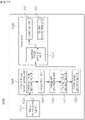
- FIG. 2 is a block diagram illustrating an environment learning device of an autonomous mobile robot according to an embodiment of the present invention.
- the environment learning device 10 of an autonomous mobile robot includes an environment information acquiring unit 100, a movement environment recognizing unit 200, and an updating unit 300.
- the environment learning device 10 of the autonomous mobile robot is a device for applying a function of recognizing an object and an environment to an autonomous mobile robot which needs to perform the autonomous moving and charging.
- the autonomous mobile robot can be used for an application which finally recognizes objects such as furniture to find out the location using the environment learning device.
- the autonomous mobile robot may include autonomous mobile robots such as a cleaning robot, a logistics robot, and a service robot and an autonomous mobile robot which requires charging.
- autonomous mobile robots such as a cleaning robot, a logistics robot, and a service robot and an autonomous mobile robot which requires charging.
- the environment learning device 10 of an autonomous mobile robot executes a deep learning algorithm which allows a robot to create a map after charging the robot and load environment information acquired during the autonomous movement to recognize the environment, in a state in which the autonomous movement finishes, and checks the locations of the recognized objects to mark the locations on the map.
- the processor since the deep learning algorithm is executed during the charging time, the processor may be sufficiently used and since a time for charging is guaranteed, a sufficient spare time may be ensured.
- a system may be implemented with low system specifications because a separate process for running the deep learning during the movement is not necessary and a robot may be called or sent from or to a desired location without running a deep learning algorithm during the driving of the robot because a location of the object is marked on the map.
- the environment information acquiring unit 100 determines feature points for recognizing an object located in the moving area and loads selected environment information in accordance with the determined feature points from the memory, using at least some of environment information which is already acquired by the autonomous mobile robot in a state in which a power is managed by a predetermined reference or higher during the movement, the environment information and the movement map information stored in the memory 101 which stores the movement map information generated with regard to the moving area where the autonomous mobile robot moves.
- the predetermined reference refers to a case when the robot is being charged in the docking station, a case when a charged amount of the battery is higher than a predetermined reference level, and a case when a power of a reference level or higher remains in consideration of a remaining movement route of the moving mobile robot.
- a charging mode command when a charging mode command is input, it is determined as a state for learning environment information.
- the charging mode command stops the moving process and starts the charging process and an algorithm of the environment learning device is performed during the charging process.
- a charging mode command is transmitted from a controller (not illustrated), the charging starts and when a moving mode command is transmitted, the charging stops and the autonomous movement starts.
- the process of the environment learning device may be performed.
- the movement map information includes a plurality of nodes and links which configure the movement map related to the moving area and the environment information includes image information on the moving area acquired during the movement and distance information and reflected light information extracted from three-dimensional point cloud data acquired from an external LiDAR.
- the feature point is at least one of a point whenever the autonomous mobile robot moves along a predetermined route, a point when a direction of the autonomous mobile robot is changed, and a point previously determined to recognize the object.
- the point previously determined to recognize the object refers to a point corresponding to a location where the object is most satisfactorily recognized, for example, a point where a center of the object is recognized or a point where a characteristic appearance of the object is clearly visible, or a point where an edge feature point (the most edge feature points) is easily extracted from the object.
- the edge may be extracted using a method of detecting an edge area using a sobel filter.
- the environment information is data for every location of the point to perform object detection and recognition and the environment information acquiring unit 100 allows a virtual robot to instantaneously acquire data from information or a map such as a map which is created in advance and a LiDAR image while moving around.
- Information including the environment information and the movement map information may be stored in memories 101, 102, and 103 and the memories may be included in the device or combined.
- the movement environment recognizing unit 200 recognizes the object using the selected environment information.
- the selected environment information refers to environment information acquired from feature points which are determined to recognize an object among the environment information and the object detection and recognition are performed using the acquired environment information.
- the updating unit 300 updates the movement map using the object information in accordance with the recognized object.
- the object information may include object recognition information indicating that the object is a "table", location information regarding a location of the table, and mobility information indicating that the table is mainly fixed to be used.
- the updating unit 300 matches the recognized object and the map information to estimate a location on the map.
- the movement map is updated by marking a category and information of the object in a location of the object recognized on a map of the object recognized by matching a coordinate of a corresponding feature node of the recognized object information and a coordinate of a movement map for the moving area.
- a system may be implemented with low system specifications because a separate process for running the deep learning during the movement is not necessary and a robot may be called or sent from or to a desired location without running a deep learning algorithm during the driving of the robot because a location of the object is marked on the map.
- FIG. 3 is a block diagram illustrating an environment information acquiring unit of an environment learning device of an autonomous mobile robot according to an embodiment of the present invention.
- the environment information acquiring unit 100 of the autonomous mobile robot includes a feature point determining unit 110 and a loading unit 120.
- the environment information acquiring unit 100 generates data acquired at a moment when the robot passes the location, among data acquired during the movement of the autonomous mobile robot and acquires the location of the robot and all data generated at that time while replaying the stored data to convert the data to perform the object detection and recognition.
- the environment information acquiring unit 100 determines feature points for recognizing an object located in the moving area and loads selected environment information in accordance with the determined feature points from the memory, using at least some of environment information which is already acquired by the autonomous mobile robot in a state in which a power is managed by a predetermined reference or higher during the movement, the environment information and the movement map information stored in the memory which stores the movement map information generated with regard to the moving area where the autonomous mobile robot moves.
- the environment information acquiring unit 100 turns off a process for autonomous movement of the robot and turns on a process for object detection and recognition.
- the movement map information includes a plurality of nodes and links which configure the movement map related to the moving area and the environment information includes image information on the moving area acquired during the movement and distance information and reflected light information extracted from three-dimensional point cloud data acquired from an external LiDAR.
- the movement map may be a three-dimensional map or a two-dimensional map
- the image information on the moving area may be image data
- the data acquired from the LiDAR may be three-dimensional or two-dimensional LiDAR data.
- the feature point determining unit 110 determines a feature point to recognize an object located in the moving area using at least some of the environment information and the movement map information stored in the memory.
- the feature point determining unit 110 specifies the feature point as a feature node, among nodes which configure the movement map and assigns numbers to nodes in accordance to an order of specifying the feature nodes.
- the loading unit 120 loads the selected environment information in accordance with the determined feature point from the memory and loads environment information stored when the autonomous mobile robot is located at the feature node in accordance with the order of the specified feature nodes.
- the loaded environment information includes a map, point cloud information, an image, or image information and the map is a three-dimensional or two-dimensional map.
- the point cloud information is distance (range) information and reflected light (intensity) information and the image or the image information is images taken while the robot moves.
- the loading unit 120 includes a LiDAR data loading unit 121 and an image data loading unit 123.
- the LiDAR data loading unit 121 loads the distance information and the reflected light information extracted from three-dimensional point cloud data acquired from the LiDAR when the autonomous mobile robot is located at the feature node during the movement.
- the image data loading unit 123 loads the image information on the moving area acquired from the image information acquiring unit 12 when the autonomous mobile robot is located at the feature node during the movement.
- a data converting unit which converts the loaded environment information into a format which performs object detection and recognition may be further provided.
- FIGS. 4 to 6 are views for explaining a movement map of an environment learning device of an autonomous mobile robot according to an embodiment of the present invention.
- FIG. 4 illustrates a movement map of an environment learning device of an autonomous mobile robot according to an embodiment of the present invention.
- the autonomous mobile robot stores points which are features while generating a map and also stores environment information at that point.
- a node of the graph may be used as the feature point.
- simultaneous localization and map-building or simultaneous localization and mapping refers to a task which creates a precise map for the environment only using a sensor attached to the robot without having the help from the outside, while the robot moves around an unknown environment.
- FIG. 4 illustrates node information which can be used as feature points on the map created by the graph SLAM and referring to FIG. 4 , the movement map 400 is configured by a plurality of nodes 401 and 410 and a link 420.
- each point refers to a node and a dotted line refers to an edge.
- the nodes 401 refers to one point where the autonomous mobile robot moves and the link 420 refers to a moving route of the autonomous mobile robot which connects the nodes.
- the feature point determining unit 110 specifies the feature point as a feature node 410, among the nodes 401 which configure the movement map and assigns numbers to the nodes in accordance to the order of specifying the feature nodes.
- the feature point may be at least one of a point whenever the autonomous mobile robot moves along a predetermined route, a point when the route of the autonomous mobile robot suddenly changes, and a point when the image information acquiring unit of the autonomous mobile robot faces to the center.
- the autonomous mobile robot located at each node moves to a first direction D1 or a second direction D2 on the route.
- the feature point may be stored whenever the robot moves by a predetermined distance or a point where a center of a space or feature points suddenly change may be stored as a feature point.
- the autonomous mobile robot When the autonomous mobile robot recognizes an object using a 3D LiDAR, distance (range) information and reflected light (intensity) information acquired at each feature point 410 by the LiDAR, and location information of the robot are stored together.
- an image acquired at each feature point and the location information of the robot are stored.
- the loading unit 120 loads environment information stored when the autonomous mobile robot is located at the feature node, in accordance with the order of specified feature nodes.
- the data is loaded in accordance with the node number and when the object is recognized using the 3D LiDAR, the location information of the point cloud and the reflected light information of the point cloud are loaded to configure a recognizer.
- FIG. 5 specifically illustrates a movement map of an environment learning device of an autonomous mobile robot according to an embodiment of the present invention.
- a method of specifying a node and loading data by the environment learning device of the autonomous mobile robot according to the embodiment of the present invention will be described with reference to FIG. 5 .
- feature points where the autonomous mobile robot moves are specified as a first feature node 411, a second feature node 412, a third feature node 413, and a fourth feature node 414 and numbers of #1, #2, #3, and #4 are assigned in accordance with the order of specifying the nodes.
- first feature node 411 is located between the first link 421 and the second link 422 and the direction is suddenly changed from a direction L1 of the first link to a direction L2 of the second link at a corner of the object.
- the second feature node 412 is located between the second link 422 and the third link 423 and is located in the middle M of the object and the direction L3 of the second link and a direction L4 of the third link coincide.
- the third feature node 413 is located between the third link 423 and the fourth link 424 and the direction is suddenly changed from a direction L5 of the third link to a direction L6 of the fourth link at a corner of the object.
- the feature point may be at least one of a point whenever the autonomous mobile robot moves along a predetermined route, a point when the route of the autonomous mobile robot suddenly changes, and a point when the image information acquiring unit of the autonomous mobile robot faces to the center.
- the autonomous mobile robot located at each node moves to the first direction D1 or the second direction D2 on the route.
- the loading unit 120 loads environment information stored when the autonomous mobile robot is located at the feature node, in accordance with the order of specified feature nodes #1, #2, #3, and #4.
- the environment information is loaded in accordance with the node number and when the object is recognized using the 3D LiDAR, the location information of the point cloud and the reflected light information of the point cloud are loaded to configure a recognizer.
- FIG. 6 illustrates a process of acquiring image information of an autonomous mobile robot from a movement map of an environment learning device of an autonomous mobile robot according to an embodiment of the present invention.
- the image information acquiring unit of the autonomous mobile robot may photograph a front side T1 and sides T2 and T3 of the obstacle on the feature nodes 1a, 1b, and 1c.
- An area S in accordance with a rotation angle of a camera may be photographed when the front side of the obstacle is seen from the feature node 1a. Thereafter, when the data is retrieved, obstacles seen from the front side and the sides are compared to specifically identify the obstacle. Further, a stationary obstacle and a moving obstacle may be compared by being compared with LiDAR data.
- FIG. 7 is a block diagram illustrating a movement environment recognizing unit of an environment learning device of an autonomous mobile robot according to an embodiment of the present invention.
- a movement environment recognizing unit 200 of an autonomous mobile robot includes a LiDAR data recognizing unit 210, an image data recognizing unit 220, and an object information matching unit 230.
- the movement environment recognizing unit 200 inputs converted information to a deep learning engine to perform object detection and recognition.
- the movement environment recognizing unit 200 recognizes the object using the selected environment information.
- the movement environment recognizing unit 200 recognizes object information included in a surrounding environment of the feature points using a convolutional neural network (CNN) method.
- CNN convolutional neural network
- the convolutional neural network is designed to classify a new image because a layer is configured to extract a characteristic of the image from an existing neural network.
- a model of the movement environment recognizing unit is not necessarily limited to a model trained by a convolutional neural network technique and a model trained by a different type of deep learning technique may also be used.
- the movement environment recognizing unit may be configured to include a deep learning unit to determine a filter coefficient by performing the learning in advance to determine a filter coefficient of the convolution neural network, with a feature point extracted from training data which has been classified in advance as an input. Further, the learning to determine a filter coefficient may be performed during the charging.
- the LiDAR data recognizing unit 210 recognizes an object included in the surrounding environment of the feature points, based on the distance information and the reflected information loaded from the LiDAR data loading unit.
- the image data recognizing unit 220 recognizes an object included in the surrounding environment of the feature points, based on the image information loaded from the image data loading unit.
- the object information matching unit 230 specifically classifies the object information by comparing object information recognized by the LiDAR data recognizing unit and object information recognized by the image data recognizing unit for every coordinate of the feature node.
- the object information matching unit classifies the object in consideration of a determination result in the image data recognizing unit and a determination result in the LiDAR data recognizing unit. If the determination result in the image data recognizing unit and a determination result in the LiDAR data recognizing unit are different from each other, the object may be classified in accordance with a result added by varying a weight in accordance with the situation. For example, when the lighting is dark, the object information matching unit classifies the object by assigning a higher weight to the determination result of the LiDAR data recognizing unit.
- location information of the point cloud where the recognized object is present may be acquired directly from the input data.
- the image based object recognition it depends on whether the LiDAR is applied. Specifically, when the 3D LiDAR is mounted, the 3D LiDAR and the image match to acquire three-dimensional location information which is projected onto the image may be acquired. When the 2D LiDAR is mounted, information of a wall on the map acquired from the 2D LiDAR and image information match to match an object recognized from the image and the location information.
- a location of the recognized object is estimated by matching a map created while the autonomous mobile robot moves and a location and a field of view of the robot.
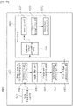
- FIG. 8 is a view for explaining a LiDAR data recognizing unit of an environment learning device of an autonomous mobile robot according to an embodiment of the present invention.
- the LiDAR data recognizing unit 210 of the autonomous mobile robot includes a first input unit 211, a first shape extracting unit 212, and a first object recognizing unit 213.
- the LiDAR data recognizing unit 210 recognizes an object included in the surrounding environment of the feature points, based on the distance information and the reflected light information loaded from the LiDAR data loading unit.
- the first input unit 211 receives the distance information and the reflected light information acquired from the LiDAR data loading unit.
- the first shape extracting unit 212 extracts shapes of the objects included in the surrounding environment of the feature points by combining or filtering cross-sections of candidate objects from points of the point cloud data, based on the distance information and the reflected light information.
- the point cloud data has a format which can be used by the LiDAR data recognizing unit 210 and may be extracted from scan information in the form of xyz or las using a drawing design/manufacturing program which can be loaded.
- the point cloud data may include an image representing a shape which represents an outline, a shape, or a structure of a candidate object which is determined as an object.
- the first shape extracting unit 212 may cut cross-sections at a plurality of predetermined reference heights to combine or filter the cross-sections.
- various heights such as 30 cm, 50 cm, and 1 m may be specified in advance and it is identified whether there is a protrusion in a medium height of the object, or there is a protrusion at a height of the top, or there is a specific object at a height of a bottom, through the filtering.
- the first object recognizing unit 213 recognizes the object by classifying the shapes of the objects in accordance with an attribute, from the extracted shapes of the objects.
- a type of the recognized object is output from the output unit 214 and object information in accordance with the output object is marked in the previously stored movement map.
- FIG. 9 is a view for explaining an image data recognizing unit of an environment learning device of an autonomous mobile robot according to an embodiment of the present invention.
- the image data recognizing unit 220 of the autonomous mobile robot includes a second input unit 221, a second shape extracting unit 222, and a second object recognizing unit 223.
- the second input unit 221 receives the image information acquired from the image data loading unit.
- the second shape extracting unit 222 extracts shapes of the objects included in the surrounding environment of the feature points by combining or filtering cross-sections of candidate objects from points of the image information on the moving area included in the image information.
- Cross-sections at a plurality of predetermined reference heights are cut to be combined or filtered.
- various heights such as 30 cm, 50 cm, and 1 m may be designated in advance and it is identified whether there is a protrusion in a medium height of the object, or there is a protrusion at a height of the top, or there is a specific object at a height of a bottom, through the filtering.
- the second object recognizing unit 223 recognizes the object by classifying the shapes of the objects in accordance with an attribute, from the extracted shapes of the objects.
- a type of the recognized object is output from the output unit 224 and object information in accordance with the output object is marked in the previously stored movement map.
- the environment learning device of the autonomous mobile robot uses a 3D LiDAR and an image based object recognizing system and thus differences caused when two systems are individually used may be compensated.
- FIGS. 10A and 10B are views for explaining an object information matching unit of an environment learning device of an autonomous mobile robot according to an embodiment of the present invention.
- FIG. 10A illustrates a TV and a wooden TV cabinet and FIG. 10B illustrates a cabinet made of glass.
- FIGS. 10A and 10B illustrate an example acquired from a node #10 corresponding to a tenth feature node.
- the LiDAR data recognizing unit recognizes the TV cabinet 241 and a space from the TV cabinet to determine that the object is a piece of furniture with a clearance.
- the image data recognizing unit identifies that the object is a piece of furniture with a clearance and the inside of the cabinet is made of wood which does not reflect and the TV 243 is located on the top.
- the object information matching unit matches a result of determining that the object is a cabinet corresponding to information of the furniture with a clearance recognized by the LiDAR data recognizing unit and a result of determining that the object is the wooden furniture as determined by the image data recognizing unit to specifically determine that the object which is recognized as an existing obstacle is a TV cabinet made of wood.
- the LiDAR data recognizing unit determines that there is a cabinet 245 and identifies that the cabinet is located without a clearance from the floor.
- the image data recognizing unit identifies that the inside of the cabinet reflects light and thus determines that it has a glass door 244 or the inside is empty.
- the object information matching unit matches a result of determining that the object is a cabinet which is located without a clearance from the floor as determined by the image data recognizing unit and a result of determining that the object is the furniture made of glass as determined by the image data recognizing unit to specifically determine that the object which is recognized as an existing obstacle is a cabinet made of a glass material.
- the object information may be further specifically classified using the object information matching unit of the present invention.
- the autonomous mobile robot may clean the inside of the furniture depending on the height of the clearance.
- the autonomous mobile robot may be controlled to be driven by adjusting a distance to the obstacle to prevent the collision.
- the object information matching unit may compare object information recognized by the LiDAR data recognizing unit and object information recognized by the image data recognizing unit.
- the object information may be classified in detail by comparing the object information for every coordinate of the feature nodes.
- the object information of the order #10 illustrated in FIG. 10 nodes of the order #9 and the order #11 are compared and at each node, the object information may be compared in accordance with the feature point of the image.
- the dog When the dog is recognized even at the nodes of the order #9 and the order #11, it is determined as an actual alive dog and when a side of the still stuffed dog is recognized by the image data recognizing unit, it is determined as a stuffed dog so that the movement of the autonomous mobile robot may be controlled.
- the object information matching unit may classify the object by assigning weights of the object information of the LiDAR data recognizing unit and the object information recognized by the image data recognizing unit which vary depending on the situation.
- a weight is applied to a still object and when an obstacle is recognized from the floor, a weight is applied to a moving object. Further, like an obstacle related to the object, a doghouse is recognized together with the dog, the weight is applied to the dog.
- FIGS. 11 to 14 are flowcharts illustrating an environment learning method of an autonomous mobile robot according to an embodiment of the present invention.
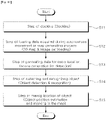
- FIG. 11 is a flowchart illustrating an environment learning method of an autonomous mobile robot according to an embodiment of the present invention.
- the environment learning method of an autonomous mobile robot starts from a step S1 1 of docking the autonomous mobile robot to be charged.
- the processor starts after the robot docks in step S11.
- a process for autonomous movement of the robot is turned off and a process for object detection and recognition is turned on.
- step S12 a processor loads data acquired during the autonomous movement of the robot or a map generating process.
- step S12 data acquired during the autonomous movement or the map generating process is loaded.
- a three-dimensional or two-dimensional map may be used and three-dimensional or two-dimensional LiDAR data or image data may be used.
- a map includes a three-dimensional or two-dimensional map
- point cloud information includes distance (range) information or reflected light (intensity) information
- image or image information includes images photographed while the robot moves.
- step S13 data for every location at the moment when the robot passes one point, among the loaded data, is generated.
- step S13 data for every location is acquired to perform the object detection and recognition and a virtual robot instantaneously acquires data from information and a map such as a map which is created in advance and a LiDAR image while moving around.
- data acquired at a moment when the robot passes the location is generated and the location of the robot and all data generated at that time while replaying the stored data are acquired to convert the data to perform the object detection and recognition.
- step S14 an object located at one point from the data for every location is detected and recognized.
- the object detection and recognition are performed using data acquired in step S14.
- the converted information is input to a deep learning engine to perform the object detection and recognition.
- step S15 the location of the detected object is marked on the map and the environment learning method of the autonomous mobile robot according to the embodiment of the present invention ends.
- step S15 a location on the map is estimated by matching the recognized object and the map information a category and information of the object are marked in the location of the object recognized on the map. Thereafter, when a process of recognizing an object for the entire map and marking on the map finishes, the process is completed.
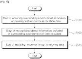
- the environment learning method of the autonomous mobile robot starts from a step S100 of loading selected environment information in accordance with a feature point from the memory, by the environment information acquiring unit.
- step S100 the environment information acquiring unit determines feature points to recognize an object located in the moving area using at least some of environment information and movement map information stored in the memory and loads the selected environment information in accordance with the determined feature point from the memory.
- the environment information acquiring unit 100 determines feature points for recognizing an object located in the moving area and loads selected environment information in accordance with the determined feature points from the memory, using at least some of environment information which is already acquired by the autonomous mobile robot in a state in which a power is managed by a predetermined reference or higher during the movement, the environment information and the movement map information stored in the memory 101 which stores the movement map information generated with regard to the moving area where the autonomous mobile robot moves.
- the predetermined reference may be a case when the robot is being charged in the docking station, a case when a charged amount of the battery is higher than a predetermined reference, and a case when an amount of power which is higher than the reference value remains in consideration of a remaining movement route of the mobile robot which is moving.
- a charging mode command when a charging mode command is input, it is determined as a state for learning the environment information.
- the charging mode command stops the moving process and starts a charging process and an algorithm of the environment learning device is performed during the charging process.
- the charging mode command is transmitted from a controller (not illustrated), the charging starts and when the moving mode command is transmitted, the charging is stopped and the autonomous movement starts.
- the process of the environment learning device may be performed.
- the movement map information includes a plurality of nodes and links which configure the movement map related to the moving area and the environment information includes image information on the moving area acquired during the movement and distance information and reflected light information extracted from three-dimensional point cloud data acquired from an external LiDAR.
- the feature point may be at least one of a point whenever the autonomous mobile robot moves along a predetermined route, a point when the route of the autonomous mobile robot suddenly changes, and a point when the image information acquiring unit of the autonomous mobile robot faces to the center.
- the location data is data for every location to perform object detection and recognition and the environment information acquiring unit 100 allows a virtual robot to instantaneously acquire data from information and a map such as a map which is created in advance and a LiDAR image while moving around.
- step S200 the movement environment recognizing unit recognizes the object using the selected environment information.
- step s300 the updating unit updates the movement map using the object information in accordance with the recognized object.
- the movement map is updated by matching a coordinate of the feature node of the recognized object information and a coordinate of the movement map for the moving area.
- the feature point determining unit specifies the feature point as a feature node among the nodes which configure the movement map and assigns a number for every node in accordance with an order of specifying the feature node, in step S110.
- the loading unit loads environment information stored when the autonomous mobile robot is located at the feature node, in accordance with the order of specified feature nodes.
- the LiDAR data loading unit loads the distance information and the reflected light information extracted from three-dimensional point cloud data acquired from the LiDAR when the autonomous mobile robot is located at the feature node during the movement.
- step S123 the image data loading unit loads image information on the moving area acquired from the image information acquiring unit when the autonomous mobile robot is located in the feature node during the movement.
- step S200 of recognizing object information included in the surrounding environment the object information included in the surrounding environment of the feature points is recognized using the convolutional neural network (CNN) method.
- CNN convolutional neural network
- the LiDAR data recognizing unit recognizes object information included in the surrounding environment of the feature points, based on the distance information and the reflected light information acquired from the LiDAR data loading unit.
- step S211 the first input unit 211 receives the distance information and the reflected light information acquired from the LiDAR data loading unit.
- the first shape extracting unit 212 extracts shapes of the objects included in the surrounding environment of the feature points by combining or filtering cross-sections of candidate objects from points of the point cloud data, based on the distance information and the reflected information.
- step S213 the first object recognizing unit 213 classifies the objects in accordance with the attribute, from the extracted shape of the objects, to determine a type of objects recognized by the autonomous mobile robot and recognize it as object information.
- a type of the recognized object is output from the output unit 214 and the output type of object is marked in the previously stored movement map.
- the image data recognizing unit recognizes object information included in the surrounding environment of the feature points, based on the image information acquired from the image data loading unit.
- step S221 the second input unit 221 receives the image information acquired from the image data loading unit.
- step S222 the second shape extracting unit 222 extracts shapes of the objects included in the surrounding environment of the feature points by combining or filtering cross-sections of candidate objects from points of the image information on the moving area included in the image information.
- step S223 the second object recognizing unit 223 classifies the objects in accordance with the attribute, from the extracted shape of the objects, to determine a type of objects recognized by the autonomous mobile robot and recognize it as object information.
- a type of the recognized object is output from the output unit 224 and the output type of object is marked in the previously stored movement map.
- the environment learning device of the autonomous mobile robot uses a 3D LiDAR and an image based object recognizing system and thus differences when two systems are individually used may be compensated.
- the object information matching unit specifically classifies the object information by comparing object information recognized by the LiDAR data recognizing unit and object information recognized by the image data recognizing unit for every coordinate of the feature nodes.
- a computer readable recording medium in which a program for allowing the computer to execute the environment learning method of the autonomous mobile robot is recorded is provided.
- An object recognizing device 1500 of the present invention is installed in a mobile robot to recognize objects in the vicinity of the mobile robot to perform an operation for efficiently cleaning the vicinity, such as, a moving direction and a moving mode.
- the mobile robot of the present invention refers to a device designed to be movable from a specific position to another position according to a predetermined method and moves from the specific position to another position using a moving unit such as wheels, rails, or walking legs.
- the mobile robot may collect external information using a sensor and then move according to the collected information or move using a separate manipulating unit by a user.
- Examples of the mobile robot of the present invention include robot cleaners, toy cars, or mobile robots for industrial or military purposes.
- the mobile robot may move using wheels or walk using one or more legs, or may be implemented by a combination thereof.
- the robot cleaner is a device which sucks foreign materials such as dust accumulated on a floor while moving in a cleaning space to automatically clean the cleaning space. Differently from a normal cleaner which moves by an external force provided by a user, the robot cleaner cleans the cleaning space while moving using external information or a predetermined moving pattern.
- the robot cleaner may automatically move using a predetermined pattern or detect external obstacles using a detecting sensor and then moves as it is detected. Further, the robot cleaner may move in accordance with a signal transmitted from a remote control device which is manipulated by the user.
- FIG. 15 is a block diagram schematically illustrating a configuration of an object recognizing device according to an embodiment of the present invention.
- an object recognizing device 1500 of the present invention includes a three-dimensional LiDAR 1510, an object image reconfiguring unit 1520, and a processor 1530.
- an object image generating device according to an embodiment of the present invention may include the three-dimensional LiDAR 1510 and the object image reconfiguring unit 1520 of FIG. 15 . That is, the object recognizing device includes an object image generating device, which is a repeated concept so that the configuration of the object recognizing device will be described in more detail.
- the three-dimensional LiDAR 1510 may be implemented as a laser radar having a distance range which detects distant objects, a viewing angle range such as azimuth and elevation, and an excellent spatial resolution.
- the LiDAR is a device which transmits a laser signal, measures a returning time of the reflected signal, and measures a distance to a reflector using a speed of light.
- the laser signal is converted into an electrical signal by a photo diode.
- the laser signal may have a predetermined wavelength band.
- the three-dimensional LiDAR 1510 of the present invention transmits and receives an optical signal using a pair of light sources and a photo diode and three-dimensionally scans surroundings using a movable mirror and a rotor.
- the three-dimensional LiDAR 1510 may operate by a time of flight (TOF) manner.
- TOF time of flight
- a laser emits a pulsed or square wave signal to measure a time when reflection pulses or square wave signals from objects within a measurement range reach a receiver to measure a distance between an object to be measured and the distance measuring apparatus.
- the laser signal irradiated by the three-dimensional LiDAR 1510 is irradiated with very narrow intervals while moving vertically and horizontally, distance information in accordance with the laser signal reflected by the objects are collected to acquire three-dimensional information of a surrounding environment of the three-dimensional LiDAR.
- the three-dimensional LiDAR 1510 of the present invention is installed on a top surface of the mobile robot to transmit and receive a laser signal in a predetermined periodic interval to and from the surrounding environment in a range of 360 degrees while autonomously rotating to acquire a point cloud including information about the object. Further, the mobile robot is fixed in a location where the mobile robot recognizes an object or moves at a timing for recognizing the object to transmit or receive the laser signal.
- the three-dimensional LiDAR will be described in more detail below with reference to FIG. 16 .
- the three-dimensional LiDAR 1510 may generate a point cloud which represents locations of the objects based on a laser signal (optical signal) reflected by the object.
- the object image reconfiguring unit 1520 may generate images representing distance information or surface information of the objects based on the point cloud.
- the three-dimensional LiDAR 1510 generates the point cloud by representing three-dimensional location information of the objects which can be calculated from the received laser signal in the form of points. That is, the point cloud is represented by expressing the three-dimensional location information of all surrounding objects acquired by the laser signal received by the three-dimensional LiDAR 1510 as a set of countless points so that it can be expressed in a shape as if water droplets form a cloud.
- the point cloud is configured by a number of measuring point groups which are densely emitted from the three-dimensional LiDAR to be reflected from the object and return to the receiver and each measuring point group has a location coordinate of x, y, and z.
- the three-dimensional LiDAR provides information in the form of a number of measuring points including a three-dimensional location, that is, a point cloud, by densely sampling a target surface of a distance of a space for each point with respect to the centric coordinate system.
- the viewpoint may freely move.
- the measurement information for the space is provided to improve the problem of the image information and when the three-dimensional printer is utilized, a three-dimensional shape may be easily constructed and manufactured.
- the point cloud according to the embodiment of the present invention may be generated as a three-dimensional image like an image 2200 illustrated in an upper portion of FIGS. 21 and 22 .
- the processor 1530 may recognize the object by learning using the images generated from the object image reconfiguring unit 1520.
- FIG. 16 is a block diagram schematically illustrating a configuration of a three-dimensional LiDAR 1510 according to an embodiment of the present invention.
- the three-dimensional LiDAR 1510 of the present invention includes a light source 1511, an optical signal transmitting unit 1512, an optical signal detecting unit 1513, and a point cloud generating unit 1514.
- the light source 1511 generates a laser signal.
- the optical signal transmitting unit 1512 transmits the laser signal generated from the light source 1511 to objects in the vicinity of the mobile robot with a predetermined time interval.
- the optical signal detecting unit 1513 may receive a laser signal transmitted from the optical signal transmitting unit 1512 which is reflected and returns from the surrounding objects to detect a signal intensity including an amount of light of the received laser signal.
- the point cloud generating unit 1514 calculates a time from a timing when the laser signal is received from the optical signal transmitting unit 1512 to a timing when the transmitted laser signal which is reflected and returns from the object is received to measure a distance from the three-dimensional LiDAR 1510 to at least one point of the object. By doing this, the point cloud generating unit 1514 generates the point cloud as an electric signal using information about the measured distance and the detected signal intensity to transmit the electric signal to the object image reconfiguring unit 1520.
- FIGS. 17 and 19 are block diagrams more specifically illustrating a configuration of an object recognizing device 1500 according to another embodiment of the present invention and FIGS. 18 and 20 are conceptual views illustrating to explain an operation algorithm of an object recognizing device according to an embodiment of the present invention.
- FIGS. 17 and 18 are views illustrating an operation flow in a learning step of more effectively recognizing an object using object information acquired by the object recognizing device and FIGS. 19 and 20 are views illustrating an operation flow at a timing when the object is recognized using object information acquired in real time after completing all the learning.
- FIGS. 17 and 18 are views illustrating an operation flow in a learning step of more effectively recognizing an object using object information acquired by the object recognizing device
- FIGS. 19 and 20 are views illustrating an operation flow at a timing when the object is recognized using object information acquired in real time after completing all the learning.
- the object image reconfiguring unit 1520 of the present invention includes a feature image generating unit 1521, an image filter unit 1522, an image pre-processing unit 1523, a hybrid image generating unit 1524, and a color image generating unit 1525.
- the feature image generating unit 1521 may generate a plurality of images for objects in accordance with a distance to the objects and an intensity of the reflected signal using a point cloud which is transmitted as an electric signal from the three-dimensional LiDAR 1510. To be more specific, the feature image generating unit 1521 may generate a two-dimensional depth image including distance information about a distance to the object and a two-dimensional intensity image including surface information about a surface characteristic of the object.
- the depth image is the same meaning as a distance (range) image and has a pixel value corresponding to the distance.
- the feature image generating unit 1521 may generate a depth image formed of information about a distance between at least one point of the three-dimensional LiDAR 1510 and at least one point of one of the objects, by projecting the three-dimensional point cloud in the two-dimensional space.
- FIG. 21 is a view illustrating that a depth image is generated using a point cloud according to an embodiment of the present invention.
- an image 2200 in the upper portion is a point cloud which is a three-dimensional image and an image 2100 in the lower portion is a depth image (distance image) which is a two-dimensional image.
- the depth image of the present invention may be generated as a light gray color image, different from an image acquired by a normal camera.
- the image acquired by the normal camera is generated by sensing color reflected by visible ray, but the depth image of the present invention may express the distance between the three-dimensional LiDAR 1510 and the object with colors.
- the feature image generating unit 1521 may determine each pixel value of a depth image corresponding to a location of at least one point of the object in accordance with a distance between at least one point of the three-dimensional LiDAR 1510 and at least one point of each object. That is, a color of the depth image of the present invention may be determined in accordance with a distance to the object, like the image 2210 of the lower portion of FIG. 21 .
- the feature image generating unit 1521 may generate an intensity image formed by information for object surface features by projecting the point cloud into a two-dimensional space, in consideration of intensities of a laser signal which is reflected and returns from at least one point of one of the objects included in the three-dimensional point cloud.
- FIG. 22 is a view illustrating that an intensive image is generated using a point cloud according to an embodiment of the present invention.
- an image 2200 in the upper portion is a point cloud which is a three-dimensional image and an image 2220 in the lower portion is an intensity image which is a two-dimensional image.
- the intensity image according to the embodiment represents information which is similar to an image acquired by a normal camera.
- the laser signal which is transmitted and received by the three-dimensional LiDAR 1510 of the present invention uses a band of an infrared ray, rather than a visible ray band so that the intensity image is represented as an image which is different from an image acquired by a normal camera.
- the depth image of the present invention represents surrounding objects only with distances from the objects so that a feature of the object surface cannot be found.
- information of the transmitted laser signal which is reflected and returns from the surface of each object is reflected as it is so that all the features of the object surface may be represented like the visible ray image.
- the intensity image is data obtained by converting an intensity of the laser signal which is reflected from the object surface to return into an image so that an object surface with good reflection may be represented with a bright value and an object surface with poor reflection may be represented with a dark value.
- the image converting unit 1521 generates a depth image and an intensity image obtained by converting a point cloud which is a three-dimensional image into a two-dimensional image by mapping pixel unit signal values which form the three-dimensional point cloud onto a two-dimensional plane.
- the feature image generating unit 1521 transmits the depth image and the intensity image to the image filter unit 1522 after generating the depth image (range image) and the intensity image for the object, based on the object information.
- the image filter unit 1522 removes an image noise of the depth image and the intensity image which are transmitted.
- the image filter unit 1522 of the present invention may be implemented as a median filter.
- the image filter unit 1522 of the present invention filters the depth image and the intensity image using a noise processing to improve the quality of the information included in the depth image and the intensity image.
- the image filter unit 1522 transmits the depth image and the intensity image from which the noise is filtered to the image pre-processing unit 1523.
- the image pre-processing unit 1523 uniformly distributes pixel values of the depth image and the intensity image which are filtered to process each image.
- the image pre-processing unit 1523 according to the embodiment performs histogram equalization on the depth image and the intensity image which are filtered to allow the process 1530 to easily distinguish the object later to output an image with an improved image quality by uniformly distributing the distribution of the pixel values of the images.
- the image pre-processing unit 1523 transmits the depth image and the intensity image which are processed to the hybrid image generating unit 1524.
- the hybrid image generating unit 1524 generates a hybrid image to allow the color image generating unit 1525 to generate a color image.
- the depth image and the intensity image which is processed by the image pre-processing unit 1523 are image information formed of one image so that the depth image and the intensity image are generated as a black and white image (gray images).
- the color image is generated only by combining three images RGB each formed of single information. That is, two images are generated by the feature image generating unit 1521 so that the one another image needs to be generated using the two generated images.
- FIG. 23 is a reference view illustrating a process of generating a color image according to an embodiment of the present invention.
- the hybrid image generating unit 1524 of the present invention generates a hybrid image by convoluting pixel information configured by the depth image which is processed by the image pre-processing unit 1523 and pixel information configured by the intensity image.
- the hybrid image generated as described above may be generated as a black and white (gray) image, similarly to the depth image and the intensity image.
- the color image generating unit 1525 of the present invention may generate a new color image by combining the generated hybrid image and the depth image and the intensity image which are processed.
- the hybrid image is generated by the hybrid image generating unit 1524, using the depth image and the intensity image which are processed.
- FIG. 18 which is another embodiment, it is illustrated that the depth image and the intensity image which are processed by the image pre-processing unit 1523 are directly transmitted to the color image generating unit 1525.
- the hybrid image generating unit 1524 of the present invention as illustrated in FIG. 18 , is provided as a configuration included in the color image generating unit 1525 so that the hybrid image generating unit may be implemented to generate a color image after generating the hybrid image by the color image generating unit 1525. Further, as illustrated in FIG. 17 , the hybrid image generating unit 1524 may also be implemented to be provided separately from the color image generating unit 1525.
- FIG. 24 is a view illustrating an algorithm which generates the above-described color image.
- [j] and [i] refer to j-th pixel and an i-th pixel in a combined image.
- FIG. 25 is a view illustrating a color image generated by the above-described process.
- the processor 1530 of the present invention may be configured to include a labeled image generating unit 1531, a learning unit 1532, and an object recognizing unit 1533.
- the labeled image generating unit 1531 of the present embodiment receives a color image generated by the color image generating unit 1525 and generates a labeled image in which at least one point of the received color image is labeled.
- the processor 1530 performs the learning to satisfactorily recognize the objects in the vicinity of the mobile robot.
- a portion specified by the user is represented in the color image which is input data to represent a portion to be found from the input image by the artificial neural network.
- the labeled image may be an image which further includes labeled object information obtained by labeling a specific object (for example, a chair or a table) desired by the user in the color image.
- a specific object for example, a chair or a table
- the labeled image generating unit 1531 transmits the generated labeled image and the color image to the learning unit 1532 and the learning unit 1532 inputs the color image and the labeled image which are transmitted to an artificial neural network provided therein to recognize the objects through the artificial neural network.
- FIG. 26 is a view illustrating input images which are input to an artificial neural network of a process according to an embodiment of the present invention.
- the labeled image which is generated using the color image may be generated as an image like the color image.
- the learning unit 1532 of the processor of the present invention receives the color image and the labeled image to perform the learning. That is, the learning unit 1532 receives the color image and the label image in which an object to be recognized by the object recognizing device 1500 is labeled in the color image to perform the learning.
- the learning unit 1532 of the present invention may learn the color image and the labeled image using an artificial neural network configured as a deep neural network (DNN).
- the artificial neural network of the learning unit of the present invention may be implemented as one of a convolution neural network (CNN), a recurrent neural network (RNN), and a generative adversarial network (GAN).
- CNN convolution neural network
- RNN recurrent neural network
- GAN generative adversarial network
- the learning unit 1532 includes an encoding unit, a convolution neural network (artificial neural network), and a decoding unit.
- the encoding unit receives the color image and the labeled image to encode the color image and the labeled image which are received to convert the color image and the labeled image into input feature vectors.
- the input feature vector refers to a vector matrix which represents a feature of each image.
- the convolution neural network is configured by an input layer configured of input nodes, a hidden layer configured of a plurality of hidden nodes which learns using the input color image and label information, and an output layer configured of output nodes which output a learning result to perform the learning.
- the hidden layers converts the input feature vectors into output feature vectors by performing the convolution using each input feature vector output from each input node of the input layer, weights set between the nodes, and a bias value for each node.
- the decoding unit decodes the output feature vector (vector matrix) which is a learning result output from the convolution neural network to calculate a result of recognizing the object based on the input image information.
- the recognition result may be a definition (name) of the object included in the input image information, a number of objects, a location of the object, and a size of the object.
- FIGS. 19 and 20 illustrate an operation flow at a timing when the object is recognized using object information acquired in real time after completing all the learning as mentioned above.
- the object recognizing unit 1933 of the object recognizing device 1900 of FIGS. 19 and 20 recognizes the objects currently in the vicinity of the robot based on the point cloud generated from the three-dimensional LiDAR 1910 installed at the top of the mobile robot 10, using a neural network including layers in which optimal weights between layers of the artificial neural network determined by the learning process of the learning unit 1932 for recognizing an object are set.
- the object recognizing device 1900 of FIG. 20 which is an embodiment of the present invention may be configured to further include a movement control unit 1940.
- the movement control unit 1940 controls a moving direction and a moving mode of the mobile robot 10 in consideration of a location of an object in the surrounding environment recognized from the object recognizing unit 1933.
- the movement control unit 1940 generates a map for a predetermined space, for example, an entire area of a home, a public organization, or an office to be cleaned while moving based on data about an object recognized by the object recognizing unit 1933 and controls an operation unit which performs a cleaning operation to automatically clean an area to be cleaned by sucking foreign materials such as dust, from a floor, while moving in an area to be cleaned by itself without manipulation of the user, based on the previously generated map.
- a map for a predetermined space for example, an entire area of a home, a public organization, or an office to be cleaned while moving based on data about an object recognized by the object recognizing unit 1933 and controls an operation unit which performs a cleaning operation to automatically clean an area to be cleaned by sucking foreign materials such as dust, from a floor, while moving in an area to be cleaned by itself without manipulation of the user, based on the previously generated map.
- FIG. 27 is a flowchart illustrating an object image generating method according to an exemplary embodiment of the present disclosure in accordance with a time flow.
- step S2701 the three-dimensional LiDAR 1510 transmits a laser signal (optical signal) to the surrounding object and receives a reflected optical signal reflected by the object.
- step S2702 the three-dimensional LiDAR 1510 generates a point cloud in accordance with a reflected optical signal.
- the three-dimensional LiDAR 1510 transmits the generated point cloud to the object image reconfiguring unit 1520 in step S2703.
- step S2704 the object image reconfiguring unit 1520 generates a depth image and an intensity image by projecting at least a part of the point cloud into a predetermined space in accordance with the distance to the object and the intensity of the reflected optical signal.
- step S2705 the object image reconfiguring unit 1520 mixes the depth image and the intensity image which are generated to generate a hybrid image and in step S2706, generates a color image which is reconfigured by combining the depth image, the intensity image, and the hybrid image.
- the object recognizing device of the present invention and a mobile robot including the same as described above convert three-dimensional information acquired from a 3D LiDAR into two-dimensional information to reduce a dimension of the information so that a computational amount and speed which can be driven even in a device with a small computational capacity such as a home cleaning robot may be ensured.
- the present invention is not limited to the exemplary embodiment.
- one or more components may be selectively combined to be operated within a scope of the present invention.
- all components may be implemented as one independent hardware but a part or all of the components are selectively combined to be implemented as a computer program which includes a program module which performs a part or all functions combined in one or plural hardwares.
- a computer program may be stored in a computer readable media such as a USB memory, a CD disk, or a flash memory to be read and executed by a computer to implement the exemplary embodiment of the present invention.
- the recording media of the computer program may include a magnetic recording medium or an optical recording medium.
Landscapes
- Engineering & Computer Science (AREA)
- Physics & Mathematics (AREA)
- Theoretical Computer Science (AREA)
- General Physics & Mathematics (AREA)
- Multimedia (AREA)
- Computer Vision & Pattern Recognition (AREA)
- Evolutionary Computation (AREA)
- Radar, Positioning & Navigation (AREA)
- Health & Medical Sciences (AREA)
- Artificial Intelligence (AREA)
- Computing Systems (AREA)
- Software Systems (AREA)
- General Health & Medical Sciences (AREA)
- Remote Sensing (AREA)
- Automation & Control Theory (AREA)
- Aviation & Aerospace Engineering (AREA)
- Medical Informatics (AREA)
- Databases & Information Systems (AREA)
- Computational Linguistics (AREA)
- Electromagnetism (AREA)
- Molecular Biology (AREA)
- Mathematical Physics (AREA)
- Biomedical Technology (AREA)
- Biophysics (AREA)
- Data Mining & Analysis (AREA)
- Mechanical Engineering (AREA)
- General Engineering & Computer Science (AREA)
- Life Sciences & Earth Sciences (AREA)
- Robotics (AREA)
- Optics & Photonics (AREA)
- Control Of Position, Course, Altitude, Or Attitude Of Moving Bodies (AREA)
- Image Analysis (AREA)
- Manipulator (AREA)
- Optical Radar Systems And Details Thereof (AREA)
Applications Claiming Priority (4)
| Application Number | Priority Date | Filing Date | Title |
|---|---|---|---|
| KR20190086265 | 2019-07-17 | ||
| KR1020190121799A KR102301759B1 (ko) | 2019-07-17 | 2019-10-01 | 자율 주행 이동 로봇의 충전 중 환경 학습 장치 및 환경 학습 방법 |
| KR1020190128448A KR102315483B1 (ko) | 2019-07-17 | 2019-10-16 | 객체 영상 생성 장치, 방법 및 이를 포함하는 객체 인식 장치 |
| PCT/KR2020/009431 WO2021010784A2 (fr) | 2019-07-17 | 2020-07-17 | Appareil et procédé pour effectuer une génération d'images d'objets, une reconnaissance d'objets et un apprentissage d'environnement par un robot mobile |
Publications (3)
| Publication Number | Publication Date |
|---|---|
| EP4015159A2 true EP4015159A2 (fr) | 2022-06-22 |
| EP4015159A4 EP4015159A4 (fr) | 2023-10-11 |
| EP4015159B1 EP4015159B1 (fr) | 2025-10-01 |
Family
ID=74211134
Family Applications (1)
| Application Number | Title | Priority Date | Filing Date |
|---|---|---|---|
| EP20840775.9A Active EP4015159B1 (fr) | 2019-07-17 | 2020-07-17 | Appareil et procédé pour effectuer une génération d'images d'objets, une reconnaissance d'objets et un apprentissage d'environnement par un robot mobile |
Country Status (3)
| Country | Link |
|---|---|
| US (1) | US12272141B2 (fr) |
| EP (1) | EP4015159B1 (fr) |
| WO (1) | WO2021010784A2 (fr) |
Families Citing this family (9)
| Publication number | Priority date | Publication date | Assignee | Title |
|---|---|---|---|---|
| JP7310912B2 (ja) * | 2019-11-11 | 2023-07-19 | 日本電信電話株式会社 | 3次元点群ラベル学習装置、3次元点群ラベル推定装置、方法、及びプログラム |
| CN114004882B (zh) * | 2021-09-24 | 2025-04-01 | 奥比中光科技集团股份有限公司 | 一种二维地图生成方法、装置、终端设备及存储介质 |
| CN116452837A (zh) * | 2022-01-04 | 2023-07-18 | 北京小米移动软件有限公司 | 特征匹配方法、装置、终端及存储介质 |
| CN114527755A (zh) * | 2022-02-21 | 2022-05-24 | 山东新一代信息产业技术研究院有限公司 | 一种机器人自动回桩充电的方法、设备、存储介质 |
| JP2023155822A (ja) * | 2022-04-11 | 2023-10-23 | キヤノン株式会社 | 情報処理装置、移動体、情報処理方法、及びコンピュータプログラム |
| US20230359217A1 (en) * | 2022-05-05 | 2023-11-09 | Pixart Imaging Inc. | Optical navigation device which can detect and record abnormal region |
| CN115457537B (zh) * | 2022-08-08 | 2025-07-08 | 武汉理工大学 | 多模态的墙砖识别方法、系统及装置 |
| EP4549104A4 (fr) * | 2022-08-23 | 2025-10-01 | Samsung Electronics Co Ltd | Robot se déplaçant par la commande d'un capteur lidar de tof, et son procédé de commande |
| CN115709484B (zh) * | 2023-01-09 | 2023-05-02 | 常州检验检测标准认证研究院 | 一种移动机器人安全仿真检测方法及系统 |
Family Cites Families (8)
| Publication number | Priority date | Publication date | Assignee | Title |
|---|---|---|---|---|
| KR101524020B1 (ko) * | 2009-03-06 | 2015-05-29 | 엘지전자 주식회사 | 로봇 청소기의 점진적 지도 작성 및 위치 보정 방법 |
| JP5822255B2 (ja) * | 2011-04-14 | 2015-11-24 | 株式会社豊田中央研究所 | 対象物識別装置及びプログラム |
| KR101826364B1 (ko) * | 2012-03-08 | 2018-02-06 | 현대엠엔소프트 주식회사 | 컬러 지상 라이다 측량 데이터를 이용하여 건물의 3차원 모델링 데이터를 자동으로 생성하기 위한 방법 |
| KR101868374B1 (ko) | 2016-10-20 | 2018-06-18 | 엘지전자 주식회사 | 이동 로봇의 제어방법 |
| KR101878827B1 (ko) * | 2016-11-30 | 2018-07-17 | 주식회사 유진로봇 | 다채널 라이더 기반 이동로봇의 장애물 검출 장치 및 방법, 및 이를 구비한 이동로봇 |
| KR20180134230A (ko) * | 2017-06-08 | 2018-12-18 | 삼성전자주식회사 | 청소 로봇 및 그 제어 방법 |
| KR102314539B1 (ko) | 2017-06-09 | 2021-10-18 | 엘지전자 주식회사 | 인공지능 이동 로봇의 제어 방법 |
| US10860034B1 (en) * | 2017-09-27 | 2020-12-08 | Apple Inc. | Barrier detection |
-
2020
- 2020-07-17 EP EP20840775.9A patent/EP4015159B1/fr active Active
- 2020-07-17 WO PCT/KR2020/009431 patent/WO2021010784A2/fr not_active Ceased
-
2022
- 2022-01-17 US US17/577,016 patent/US12272141B2/en active Active
Also Published As
| Publication number | Publication date |
|---|---|
| US20220139086A1 (en) | 2022-05-05 |
| WO2021010784A2 (fr) | 2021-01-21 |
| US12272141B2 (en) | 2025-04-08 |
| WO2021010784A3 (fr) | 2021-04-01 |
| EP4015159A4 (fr) | 2023-10-11 |
| EP4015159B1 (fr) | 2025-10-01 |
Similar Documents
| Publication | Publication Date | Title |
|---|---|---|
| US12272141B2 (en) | Device and method for generating object image, recognizing object, and learning environment of mobile robot | |
| KR102301759B1 (ko) | 자율 주행 이동 로봇의 충전 중 환경 학습 장치 및 환경 학습 방법 | |
| KR102275300B1 (ko) | 이동 로봇 및 그 제어방법 | |
| CN112714684B (zh) | 清洁机器人及其执行任务的方法 | |
| US20230085608A1 (en) | Modular Robot | |
| KR102670610B1 (ko) | 공항용 로봇 및 그의 동작 방법 | |
| KR20240063820A (ko) | 청소 로봇 및 그의 태스크 수행 방법 | |
| KR102348041B1 (ko) | 복수의 이동 로봇을 포함하는 로봇 시스템의 제어 방법 | |
| JP2023134626A (ja) | 少なくとも一つの幾何学情報を決定するためのレンジファインダ | |
| JP2022540160A (ja) | 人工知能を利用した移動ロボット及び移動ロボットの制御方法 | |
| US12245730B2 (en) | Systems and methods for enabling navigation in environments with dynamic objects | |
| CN110147106A (zh) | 具激光和视觉融合避障系统的智能移动服务机器人 | |
| Ding et al. | Monocular camera-based complex obstacle avoidance via efficient deep reinforcement learning | |
| TWI739255B (zh) | 移動式機器人 | |
| Peasley et al. | Real-time obstacle detection and avoidance in the presence of specular surfaces using an active 3D sensor | |
| AU2013284446A1 (en) | Pool cleaner with laser range finder system and method | |
| US20220334587A1 (en) | Method for processing map of closed space, apparatus, and mobile device | |
| KR20210051014A (ko) | 로봇 청소기 및 그의 동작 방법 | |
| US11989021B1 (en) | Method for overcoming obstructions of a robotic device | |
| Buck et al. | Generic 3D obstacle detection for AGVs using time-of-flight cameras | |
| Xanthidis et al. | Towards mapping of underwater structures by a team of autonomous underwater vehicles | |
| KR102490754B1 (ko) | 이동 로봇 시스템 | |
| KR102490755B1 (ko) | 이동 로봇 시스템 | |
| KR20230134109A (ko) | 청소 로봇 및 그의 태스크 수행 방법 | |
| WO2020038155A1 (fr) | Dispositif de déplacement autonome, procédé de contrôle et support de stockage |
Legal Events
| Date | Code | Title | Description |
|---|---|---|---|
| STAA | Information on the status of an ep patent application or granted ep patent |
Free format text: STATUS: THE INTERNATIONAL PUBLICATION HAS BEEN MADE |
|
| PUAI | Public reference made under article 153(3) epc to a published international application that has entered the european phase |
Free format text: ORIGINAL CODE: 0009012 |
|
| STAA | Information on the status of an ep patent application or granted ep patent |
Free format text: STATUS: REQUEST FOR EXAMINATION WAS MADE |
|
| 17P | Request for examination filed |
Effective date: 20220113 |
|
| AK | Designated contracting states |
Kind code of ref document: A2 Designated state(s): AL AT BE BG CH CY CZ DE DK EE ES FI FR GB GR HR HU IE IS IT LI LT LU LV MC MK MT NL NO PL PT RO RS SE SI SK SM TR |
|
| RAP1 | Party data changed (applicant data changed or rights of an application transferred) |
Owner name: MIELE & CIE. KG Owner name: YUJIN ROBOT CO., LTD. |
|
| DAV | Request for validation of the european patent (deleted) | ||
| DAX | Request for extension of the european patent (deleted) | ||
| REG | Reference to a national code |
Ref country code: DE Free format text: PREVIOUS MAIN CLASS: B25J0009160000 Ipc: G05D0001020000 Ref country code: DE Ref legal event code: R079 Ref document number: 602020059846 Country of ref document: DE Free format text: PREVIOUS MAIN CLASS: B25J0009160000 Ipc: G05D0001020000 |
|
| A4 | Supplementary search report drawn up and despatched |
Effective date: 20230908 |
|
| RIC1 | Information provided on ipc code assigned before grant |
Ipc: G06V 20/58 20220101ALI20230904BHEP Ipc: G06V 10/82 20220101ALI20230904BHEP Ipc: G06N 3/045 20230101ALI20230904BHEP Ipc: G06N 3/008 20230101ALI20230904BHEP Ipc: A47L 9/28 20060101ALI20230904BHEP Ipc: B25J 11/00 20060101ALI20230904BHEP Ipc: B25J 19/02 20060101ALI20230904BHEP Ipc: B25J 9/16 20060101ALI20230904BHEP Ipc: G05D 1/02 20200101AFI20230904BHEP |
|
| STAA | Information on the status of an ep patent application or granted ep patent |
Free format text: STATUS: EXAMINATION IS IN PROGRESS |
|
| 17Q | First examination report despatched |
Effective date: 20240807 |
|
| REG | Reference to a national code |
Ref country code: DE Ref legal event code: R079 Free format text: PREVIOUS MAIN CLASS: G05D0001020000 Ref country code: DE Ref legal event code: R079 Ref document number: 602020059846 Country of ref document: DE Free format text: PREVIOUS MAIN CLASS: G05D0001020000 Ipc: G05D0001000000 |
|
| GRAP | Despatch of communication of intention to grant a patent |
Free format text: ORIGINAL CODE: EPIDOSNIGR1 |
|
| STAA | Information on the status of an ep patent application or granted ep patent |
Free format text: STATUS: GRANT OF PATENT IS INTENDED |
|
| RIC1 | Information provided on ipc code assigned before grant |
Ipc: G06V 20/58 20220101ALI20250603BHEP Ipc: G06V 10/82 20220101ALI20250603BHEP Ipc: G06N 3/045 20230101ALI20250603BHEP Ipc: G06N 3/008 20230101ALI20250603BHEP Ipc: B25J 9/16 20060101ALI20250603BHEP Ipc: G05D 1/00 20060101AFI20250603BHEP |
|
| INTG | Intention to grant announced |
Effective date: 20250618 |
|
| GRAS | Grant fee paid |
Free format text: ORIGINAL CODE: EPIDOSNIGR3 |
|
| GRAA | (expected) grant |
Free format text: ORIGINAL CODE: 0009210 |
|
| STAA | Information on the status of an ep patent application or granted ep patent |
Free format text: STATUS: THE PATENT HAS BEEN GRANTED |
|
| AK | Designated contracting states |
Kind code of ref document: B1 Designated state(s): AL AT BE BG CH CY CZ DE DK EE ES FI FR GB GR HR HU IE IS IT LI LT LU LV MC MK MT NL NO PL PT RO RS SE SI SK SM TR |
|
| REG | Reference to a national code |
Ref country code: GB Ref legal event code: FG4D Ref country code: CH Ref legal event code: F10 Free format text: ST27 STATUS EVENT CODE: U-0-0-F10-F00 (AS PROVIDED BY THE NATIONAL OFFICE) Effective date: 20251001 |
|
| REG | Reference to a national code |
Ref country code: DE Ref legal event code: R096 Ref document number: 602020059846 Country of ref document: DE |
|
| REG | Reference to a national code |
Ref country code: IE Ref legal event code: FG4D |
|
| REG | Reference to a national code |
Ref country code: NL Ref legal event code: MP Effective date: 20251001 |
|
| REG | Reference to a national code |
Ref country code: AT Ref legal event code: MK05 Ref document number: 1843123 Country of ref document: AT Kind code of ref document: T Effective date: 20251001 |
|
| PG25 | Lapsed in a contracting state [announced via postgrant information from national office to epo] |
Ref country code: NL Free format text: LAPSE BECAUSE OF FAILURE TO SUBMIT A TRANSLATION OF THE DESCRIPTION OR TO PAY THE FEE WITHIN THE PRESCRIBED TIME-LIMIT Effective date: 20251001 |
|
| PG25 | Lapsed in a contracting state [announced via postgrant information from national office to epo] |
Ref country code: ES Free format text: LAPSE BECAUSE OF FAILURE TO SUBMIT A TRANSLATION OF THE DESCRIPTION OR TO PAY THE FEE WITHIN THE PRESCRIBED TIME-LIMIT Effective date: 20251001 |
|
| REG | Reference to a national code |
Ref country code: LT Ref legal event code: MG9D |
|
| PG25 | Lapsed in a contracting state [announced via postgrant information from national office to epo] |
Ref country code: NO Free format text: LAPSE BECAUSE OF FAILURE TO SUBMIT A TRANSLATION OF THE DESCRIPTION OR TO PAY THE FEE WITHIN THE PRESCRIBED TIME-LIMIT Effective date: 20260101 |
|
| PG25 | Lapsed in a contracting state [announced via postgrant information from national office to epo] |
Ref country code: FI Free format text: LAPSE BECAUSE OF FAILURE TO SUBMIT A TRANSLATION OF THE DESCRIPTION OR TO PAY THE FEE WITHIN THE PRESCRIBED TIME-LIMIT Effective date: 20251001 Ref country code: HR Free format text: LAPSE BECAUSE OF FAILURE TO SUBMIT A TRANSLATION OF THE DESCRIPTION OR TO PAY THE FEE WITHIN THE PRESCRIBED TIME-LIMIT Effective date: 20251001 Ref country code: AT Free format text: LAPSE BECAUSE OF FAILURE TO SUBMIT A TRANSLATION OF THE DESCRIPTION OR TO PAY THE FEE WITHIN THE PRESCRIBED TIME-LIMIT Effective date: 20251001 |
|
| PG25 | Lapsed in a contracting state [announced via postgrant information from national office to epo] |
Ref country code: RS Free format text: LAPSE BECAUSE OF FAILURE TO SUBMIT A TRANSLATION OF THE DESCRIPTION OR TO PAY THE FEE WITHIN THE PRESCRIBED TIME-LIMIT Effective date: 20260101 |
|
| PG25 | Lapsed in a contracting state [announced via postgrant information from national office to epo] |
Ref country code: IS Free format text: LAPSE BECAUSE OF FAILURE TO SUBMIT A TRANSLATION OF THE DESCRIPTION OR TO PAY THE FEE WITHIN THE PRESCRIBED TIME-LIMIT Effective date: 20260201 |
|
| PG25 | Lapsed in a contracting state [announced via postgrant information from national office to epo] |
Ref country code: CZ Free format text: LAPSE BECAUSE OF FAILURE TO SUBMIT A TRANSLATION OF THE DESCRIPTION OR TO PAY THE FEE WITHIN THE PRESCRIBED TIME-LIMIT Effective date: 20251001 Ref country code: PT Free format text: LAPSE BECAUSE OF FAILURE TO SUBMIT A TRANSLATION OF THE DESCRIPTION OR TO PAY THE FEE WITHIN THE PRESCRIBED TIME-LIMIT Effective date: 20260202 |
|
| PG25 | Lapsed in a contracting state [announced via postgrant information from national office to epo] |
Ref country code: PL Free format text: LAPSE BECAUSE OF FAILURE TO SUBMIT A TRANSLATION OF THE DESCRIPTION OR TO PAY THE FEE WITHIN THE PRESCRIBED TIME-LIMIT Effective date: 20251001 |
|
| PG25 | Lapsed in a contracting state [announced via postgrant information from national office to epo] |
Ref country code: LV Free format text: LAPSE BECAUSE OF FAILURE TO SUBMIT A TRANSLATION OF THE DESCRIPTION OR TO PAY THE FEE WITHIN THE PRESCRIBED TIME-LIMIT Effective date: 20251001 |