EP4015183A1 - Appareil de moulage par injection et procédé pour réduire l'augmentation de vitesse d'écoulement lors du moulage par injection - Google Patents
Appareil de moulage par injection et procédé pour réduire l'augmentation de vitesse d'écoulement lors du moulage par injection Download PDFInfo
- Publication number
- EP4015183A1 EP4015183A1 EP20214698.1A EP20214698A EP4015183A1 EP 4015183 A1 EP4015183 A1 EP 4015183A1 EP 20214698 A EP20214698 A EP 20214698A EP 4015183 A1 EP4015183 A1 EP 4015183A1
- Authority
- EP
- European Patent Office
- Prior art keywords
- gate
- volume
- injection
- mould cavity
- injection moulding
- Prior art date
- Legal status (The legal status is an assumption and is not a legal conclusion. Google has not performed a legal analysis and makes no representation as to the accuracy of the status listed.)
- Granted
Links
Images


Classifications
-
- B—PERFORMING OPERATIONS; TRANSPORTING
- B29—WORKING OF PLASTICS; WORKING OF SUBSTANCES IN A PLASTIC STATE IN GENERAL
- B29C—SHAPING OR JOINING OF PLASTICS; SHAPING OF MATERIAL IN A PLASTIC STATE, NOT OTHERWISE PROVIDED FOR; AFTER-TREATMENT OF THE SHAPED PRODUCTS, e.g. REPAIRING
- B29C45/00—Injection moulding, i.e. forcing the required volume of moulding material through a nozzle into a closed mould; Apparatus therefor
- B29C45/17—Component parts, details or accessories; Auxiliary operations
- B29C45/26—Moulds
- B29C45/27—Sprue channels ; Runner channels or runner nozzles
- B29C45/2701—Details not specific to hot or cold runner channels
- B29C45/2708—Gates
-
- B—PERFORMING OPERATIONS; TRANSPORTING
- B29—WORKING OF PLASTICS; WORKING OF SUBSTANCES IN A PLASTIC STATE IN GENERAL
- B29C—SHAPING OR JOINING OF PLASTICS; SHAPING OF MATERIAL IN A PLASTIC STATE, NOT OTHERWISE PROVIDED FOR; AFTER-TREATMENT OF THE SHAPED PRODUCTS, e.g. REPAIRING
- B29C45/00—Injection moulding, i.e. forcing the required volume of moulding material through a nozzle into a closed mould; Apparatus therefor
- B29C45/0046—Details relating to the filling pattern or flow paths or flow characteristics of moulding material in the mould cavity
-
- B—PERFORMING OPERATIONS; TRANSPORTING
- B29—WORKING OF PLASTICS; WORKING OF SUBSTANCES IN A PLASTIC STATE IN GENERAL
- B29C—SHAPING OR JOINING OF PLASTICS; SHAPING OF MATERIAL IN A PLASTIC STATE, NOT OTHERWISE PROVIDED FOR; AFTER-TREATMENT OF THE SHAPED PRODUCTS, e.g. REPAIRING
- B29C45/00—Injection moulding, i.e. forcing the required volume of moulding material through a nozzle into a closed mould; Apparatus therefor
- B29C45/0025—Preventing defects on the moulded article, e.g. weld lines, shrinkage marks
-
- B—PERFORMING OPERATIONS; TRANSPORTING
- B29—WORKING OF PLASTICS; WORKING OF SUBSTANCES IN A PLASTIC STATE IN GENERAL
- B29C—SHAPING OR JOINING OF PLASTICS; SHAPING OF MATERIAL IN A PLASTIC STATE, NOT OTHERWISE PROVIDED FOR; AFTER-TREATMENT OF THE SHAPED PRODUCTS, e.g. REPAIRING
- B29C45/00—Injection moulding, i.e. forcing the required volume of moulding material through a nozzle into a closed mould; Apparatus therefor
- B29C45/17—Component parts, details or accessories; Auxiliary operations
- B29C45/76—Measuring, controlling or regulating
- B29C45/77—Measuring, controlling or regulating of velocity or pressure of moulding material
-
- B—PERFORMING OPERATIONS; TRANSPORTING
- B29—WORKING OF PLASTICS; WORKING OF SUBSTANCES IN A PLASTIC STATE IN GENERAL
- B29C—SHAPING OR JOINING OF PLASTICS; SHAPING OF MATERIAL IN A PLASTIC STATE, NOT OTHERWISE PROVIDED FOR; AFTER-TREATMENT OF THE SHAPED PRODUCTS, e.g. REPAIRING
- B29C45/00—Injection moulding, i.e. forcing the required volume of moulding material through a nozzle into a closed mould; Apparatus therefor
- B29C45/0025—Preventing defects on the moulded article, e.g. weld lines, shrinkage marks
- B29C2045/0032—Preventing defects on the moulded article, e.g. weld lines, shrinkage marks sequential injection from multiple gates, e.g. to avoid weld lines
-
- B—PERFORMING OPERATIONS; TRANSPORTING
- B29—WORKING OF PLASTICS; WORKING OF SUBSTANCES IN A PLASTIC STATE IN GENERAL
- B29L—INDEXING SCHEME ASSOCIATED WITH SUBCLASS B29C, RELATING TO PARTICULAR ARTICLES
- B29L2031/00—Other particular articles
- B29L2031/30—Vehicles, e.g. ships or aircraft, or body parts thereof
- B29L2031/3044—Bumpers
Definitions
- the disclosure relates to an injection moulding apparatus and a method for reducing a velocity increase of a flow front during injection moulding.
- Injection moulding is a well-known plastic moulding technique that is used to mould plastic parts of many shapes and sizes.
- today's injection moulding apparatuses use several inlets that open in sequence, with injection of the liquid plastic often starting in the middle of the detail.
- An objective of the disclosure is to provide an injection moulding apparatus and a method addressing the issues raised.
- the objective is achieved by the injection moulding apparatus of claim 1 and the method of claim 8.
- Dependent claims provide advantageous example embodiments.
- the disclosure relates to an injection moulding apparatus comprising at least a first mould plate.
- the first mould plate comprises a first injection inlet arranged in fluid connection with a first gate leading into a mould cavity and a second injection inlet arranged in fluid connection with a second gate leading into the mould cavity.
- the first injection inlet and the second injection inlet are arranged to open in sequence, with the first injection inlet opening before the second injection inlet.
- the second gate comprises a first gate volume leading into the mould cavity.
- the second gate is further provided with a second gate volume allowing injection material to flow into the second gate volume at the same time as into the first gate volume and thereafter into the mould cavity, thereby reducing the velocity of an injection flow in the mould cavity from the second gate.
- the increased volume acts as a shock absorber for the injected liquid plastic.
- the velocity increase on the flow front of the injected material from the second gate is reduced and is in some cases reduced all the way to zero.
- One further advantage with the injection moulding apparatus according to the disclosure is that it is possible to add the second gate volume to existing injection moulding apparatuses. Even though it increases the cost relative to if it is done during the design of an injection moulding apparatus, the cost will still be significantly lower than to use intakes that are opened step by step.
- the second gate volume may be provided by a first increased volume extending from the second injection inlet in a first direction.
- the second gate volume can take many forms and in its least complex form extends in a first direction, for instance in a direction facing away from the direction that the second gate leads into the mould cavity.
- the second gate volume may be further provided by a second increased volume extending from the second injection inlet in a second direction different from the first direction. If the second gate volume needs to be increased in a way where extending the second gate volume only in a first direction does not yield a large enough second gate volume, the second gate volume can be extended in a second direction different from the first direction.
- the second direction may be perpendicular to the first direction and extend in a horizontal or vertical direction relative the extension of the first direction.
- the second direction may alternatively extend in a direction at an angle smaller or greater than 90° to the first direction.
- the second gate volume may also extend in a both positive and negative second direction; an example would be if the second gate volume is essentially T-shaped.
- the first and/or second increased volume may be in the shape of one or more of cuboids, spheroids, parallelepipeds or cylinders. Depending on the amount of space available in the in first mould plate, the first and/or second increased volume can take different shapes such that the desired second gate volume can be achieved. Various combinations of shapes can be used to achieve the desired second gate volume.
- the second gate comprises a throttle leading into the first increased volume.
- the throttle will lead to that the flow velocity of liquid plastic into the second gate volume is reduced such that the second gate volume is not filled too quickly. If the second gate volume is filled too quickly, the effect of the second gate volume is reduced.
- the throttle may have a cross sectional area between approximately 1/4 and 3/4 of a cross sectional area of the second gate volume where the throttle connects the first and second gate volumes.
- a cross sectional area of this size has been shown to provide desired fill velocities of the second gate volume. It is also desired that the material in the throttle hardens once the second gate volume is filled so as the second gate volume is not filled during the filling phase.
- a size of the second gate volume is a function of the distance between the first injection inlet and the second injection inlet.
- the injection inlets will have to be placed with different distances between them in order to achieve the desired filling and packing characteristics.
- the distance between the first and second injection inlets will determine the size, i.e. final volume of the second gate volume.
- an injection moulding apparatus comprises at least a first mould plate , the first mould plate comprising a first injection inlet arranged in fluid connection with a first gate leading into a mould cavity and a second injection inlet arranged in fluid connection with a second gate leading into a mould cavity, wherein the first injection inlet and the second injection inlet are arranged to open in sequence, with the first injection inlet opening before the second injection inlet, wherein the second gate comprises a first gate volume leading into the mould cavity, wherein the method comprises:
- the method may also comprise:
- the method may also comprise:
- the method may also comprise:
- the method may also comprise:
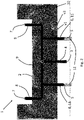
- Figure 1 schematically show a prior art injection moulding apparatus 1 during filling of a mould cavity 2.
- the injection moulding apparatus 1 comprises a first mould plate and a second mould plate (not shown).
- the first mould plate comprises a first injection inlet 3 arranged in fluid connection with a first gate 4 leading into the mould cavity 2 and a second injection inlet 5 arranged in fluid connection with a second gate 6 leading into the mould cavity 2.
- the first injection inlet 3 and the second injection inlet 5 are arranged to open in sequence, with the first injection inlet 3 opening before the second injection inlet 5.
- the mould cavity 2 has an example shape corresponding to a simplified bumper of a vehicle.
- the width of the bumper is approximately 1000 mm.
- the injection moulding apparatus 1 also comprises a third injection inlet 7 arranged in fluid connection with a third gate 8 leading into the mould cavity 2.
- the third injection inlet 7 is arranged to open in sequence after the first and second inlets 3, 5.
- the first, second and third injection 3, 5, 7 inlets are provided with liquid plastic through runners 8 which in turn is supplied from a nozzle 9 as previously known in the art.
- first injection inlet 3 has been open for some time and the second injection inlet 5 has recently opened.
- a flow front 10 is clearly visible in figure 1 .
- a first velocity v1, measured at a wall of the mould cavity 2, and a second velocity v2, measured at a distance from the wall of the mould cavity 2 indicate a flow front velocity of the injected liquid plastic and illustrate a local velocity difference that may give rise to surface defect or flow marks on the article.
- v1 is equal to approximately 57.1 cm/s and v2 is equal to approximately 45.8 cm/s.
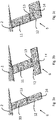
- Figure 2 schematically show an injection moulding apparatus 1 according to the disclosure during filling of a mould cavity 2.
- the difference from the injection moulding apparatus 1 of figure 1 is that the second gate 6 comprises a first gate volume 11 leading into the mould cavity 2 and the second gate 6 is further provided with a second gate volume 12 allowing injection material to flow into the second gate volume 12 at the same time as into the first gate volume 11 and thereafter into the mould cavity 2. This reduces the velocity of an injection flow in the mould cavity 2 from the second gate 6.
- the first injection inlet 3 and the second injection inlet 5 has been opened in the same sequence and as for an equally long time as in figure 1 .
- a first velocity v1 is measured at the wall of the mould cavity 2
- a second velocity v2 is measured at a distance from the wall of the mould cavity 2 indicate a flow front velocity of the injected liquid plastic.
- v1 is equal to approximately 23.3 cm/s and v2 is equal to approximately 21.7 cm/s.
- the second gate volume 12 reduces the velocity of the injection flow of liquid plastic into the mould cavity 2 from the second gate 6 as well as the local velocity difference.
- the lower velocity at the flow front 10 reduces the risk of the injection moulded article, e.g. the bumper according to the example of figures 1 and 2 , from obtaining surfaces that do not meet the desired visual appearance of the article or surfaces that are deformed due to that liquid plastic enters the mould cavity 2 at a too high velocity.
- the final volume of the second gate volume is a function of the distance between the first injection inlet 3 and the second injection inlet 5. If the first and second injection inlets 3, 5 are not situated in the same plane, the distance is measured as the radius of a sphere with the first injection inlet 3 placed in the centre of the sphere and the second injection inlet 5 situated on the surface of the sphere.
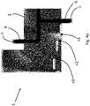
- FIGs 3a-3c schematically show a close-up view of a second gate volume 12 according to embodiments of the disclosure.
- the second gate 6 comprising a throttle 13 and the second gate volume 12 as seen in figure 2 is shown.
- the second gate volume 12 is provided by a first increased volume 14 extending from the second injection inlet 5 in mainly a first direction, where the first direction is essentially extending in the same direction as the extension of the second gate 6.
- the second gate volume 12 is provided by a first increased volume 14 extending from the second injection inlet 5 in mainly a first direction, where the first direction is perpendicular to the extension of the second gate 6.
- the second gate volume 12 is provided by a first increased volume 14 extending in both a first and a second direction, where the first direction is essentially extending in the same direction as the extension of the second gate 6 and where the second direction is perpendicular to the extension of the second gate 6.
- the second gate volume 12 being provided by a second increased volume extending from the second injection inlet 5 in a second direction different from the first direction in addition to the first increased gate volume.
- a second gate volume 12 having a T-shape.
- the second gate volume 12 in the shape of one or more of cuboids, spheroids, parallelepipeds or cylinders.
- the throttle 13 in figures 3a-3c will lead to that the flow velocity of liquid plastic into the second gate volume 12 is reduced such that the second gate volume 12 is not filled too quickly. If the second gate volume 12 is filled too quickly, the effect of the second gate volume 12 is reduced.
- the throttle 13 may have a cross sectional area between approximately 25 % and 75 % of a cross sectional area of the second gate volume 12 where the throttle 13 connects the first and second gate volumes 11, 12. A cross sectional area of this size has been shown to provide desired fill velocities of the second gate volume 12. It is also desired that the material in the throttle 13 hardens once the second gate volume 12 is filled so as the second gate volume 12 is not filled during the filling phase.
- the first and second gate volumes 11, 12 are essentially cuboid in shape and have a height of approximately 3 mm.
- the throttle 13 has a height of approximately 1 mm resulting in a cross sectional area of 33 % of a cross sectional area of the second gate volume 12 where the throttle 13 connects the first and second gate volume 11, 12.
- the effect of the throttle 13 is improved if the width of the throttle 13 is not wider than a width of the first gate volume 11.
- the interface between the second gate 6 and the mould cavity 2 is not changed.
- Examples of the height of the throttle is between approximately 0.5 - 2 mm.
- the throttle also has an extension in the same direction as the first gate volume 11.
- Examples of the extension of the throttle is between approximately 2 - 5 mm.
- Example lengths of the second gate volume in figure 3a is between 50 - 70 mm, with approximately 60 mm being a good starting point for finding the proper design length.
- the throttle is intended to be situated as close to the second injection inlet as possible to design and manufacture.
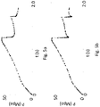
- Figures 4a-4b schematically show a more detailed view of flow velocities for the injection moulding apparatus 1 of figures 1 and 2 during filling of a mould cavity 2.
- Figure 4a schematically shows a more detailed view of flow velocities for the injection moulding apparatus 1 of figure 1 .
- the velocity is indicated at three locations in the mould cavity 2, a first velocity v1 at the flow front 10 near the second gate 6 where the velocity is highest, a second velocity v2 at a first distance from the flow front 10 and a third velocity v3 at a second distance from the flow front 10.
- the first velocity v1 is approximately 47.3 m/s
- the second velocity v2 is approximately 22.4 m/s
- the third velocity v3 is approximately 13.2 m/s.
- Figure 4b schematically shows a more detailed view of flow velocities for the injection moulding apparatus 1 of figure 2 comprising a second gate 6 provided with a second gate volume 12.
- the velocity is measured at three locations in the mould cavity 2, a first velocity v1 at the flow front near the second gate 6, a second velocity v2 at a first distance from the flow front 10 and a third velocity v3 at a second distance from the flow front 10.
- the first velocity v1 is approximately 23.0 m/s
- the second velocity v2 is approximately 21.1 m/s
- the third velocity v3 is approximately 13.1 m/s.
- Figures 5a and 5b schematically shows a comparison between an injection moulding apparatus 1 with a prior art second gate 6 according to figure 1 and an injection moulding apparatus 1 with a second gate 6 according to the disclosure.
- the comparison relates to the pressure at the nozzle 9 required to fulfil an intended fill time.
- the chart in figure 5a shows the pressure at the nozzle 9 for a prior art second gate 6, e.g. a gate such as in figure 1 .
- a prior art second gate 6 e.g. a gate such as in figure 1 .
- large pressure drops are generally interpreted as a varying flow front velocity, which is something that one tries to avoid.
- the chart in figure 5b shows the pressure at the nozzle 9 for a second gate 6 according to the disclosure, e.g. a gate such as in figure 2 .
- a second gate 6 e.g. a gate such as in figure 2 .
- large pressure drops does not indicate a varying flow front velocity as has been demonstrated in for instance figures 2 and 4b .
- the final volume of the second gate volume is dependent also on the size of the article to be injection moulded. Simulation software can be beneficial for finding the optimal second gate volume. The sizes mentioned above would in such case provide good starting values for simulations.
- the size of the runners, e.g. cross sectional area or volume, can also be optimised to add to the effect of the second gate volume.
Landscapes
- Engineering & Computer Science (AREA)
- Manufacturing & Machinery (AREA)
- Mechanical Engineering (AREA)
- Moulds For Moulding Plastics Or The Like (AREA)
Priority Applications (4)
| Application Number | Priority Date | Filing Date | Title |
|---|---|---|---|
| EP20214698.1A EP4015183B1 (fr) | 2020-12-16 | 2020-12-16 | Appareil de moulage par injection et procédé pour réduire l'augmentation de vitesse d'écoulement lors du moulage par injection |
| CN202180083752.7A CN116635202B (zh) | 2020-12-16 | 2021-11-25 | 注射成型装置和用于在注射成型期间减小流动前沿的速度增加的方法 |
| PCT/CN2021/133081 WO2022127549A1 (fr) | 2020-12-16 | 2021-11-25 | Appareil de moulage par injection et procédé pour réduire l'augmentation de vitesse du front d'écoulement pendant un moulage par injection |
| US18/205,117 US12251863B2 (en) | 2020-12-16 | 2023-06-02 | Injection moulding apparatus and method to reduce velocity increase of flow front during injection moulding |
Applications Claiming Priority (1)
| Application Number | Priority Date | Filing Date | Title |
|---|---|---|---|
| EP20214698.1A EP4015183B1 (fr) | 2020-12-16 | 2020-12-16 | Appareil de moulage par injection et procédé pour réduire l'augmentation de vitesse d'écoulement lors du moulage par injection |
Publications (2)
| Publication Number | Publication Date |
|---|---|
| EP4015183A1 true EP4015183A1 (fr) | 2022-06-22 |
| EP4015183B1 EP4015183B1 (fr) | 2024-10-09 |
Family
ID=73855153
Family Applications (1)
| Application Number | Title | Priority Date | Filing Date |
|---|---|---|---|
| EP20214698.1A Active EP4015183B1 (fr) | 2020-12-16 | 2020-12-16 | Appareil de moulage par injection et procédé pour réduire l'augmentation de vitesse d'écoulement lors du moulage par injection |
Country Status (3)
| Country | Link |
|---|---|
| US (1) | US12251863B2 (fr) |
| EP (1) | EP4015183B1 (fr) |
| WO (1) | WO2022127549A1 (fr) |
Cited By (1)
| Publication number | Priority date | Publication date | Assignee | Title |
|---|---|---|---|---|
| CN115846623A (zh) * | 2022-12-22 | 2023-03-28 | 广东鸿兴精密科技股份有限公司 | 一种新型低压铸造系统 |
Citations (5)
| Publication number | Priority date | Publication date | Assignee | Title |
|---|---|---|---|---|
| JPH06238706A (ja) * | 1993-02-16 | 1994-08-30 | Honda Motor Co Ltd | 射出成形方法 |
| JP2665112B2 (ja) * | 1992-08-25 | 1997-10-22 | 本田技研工業株式会社 | 射出成形方法及び射出成形装置 |
| JP2000254946A (ja) * | 1999-03-05 | 2000-09-19 | Tohoku Munekata Co Ltd | 射出成形用金型 |
| CN103640152A (zh) * | 2013-11-15 | 2014-03-19 | 成都航天模塑股份有限公司 | 挡泥板模具及其注塑工艺 |
| US20140232044A1 (en) * | 2011-10-11 | 2014-08-21 | Borealis Ag | Distribution system for injection moulding |
Family Cites Families (8)
| Publication number | Priority date | Publication date | Assignee | Title |
|---|---|---|---|---|
| US6063315A (en) | 1997-03-07 | 2000-05-16 | Cascade Engineering, Inc. | Gas-assisted injection molding of large panels with sequential gating |
| CA2443483C (fr) * | 2002-10-02 | 2011-08-16 | Mold-Masters Limited | Dispositif melangeur |
| DE102007052597A1 (de) * | 2007-11-03 | 2009-05-07 | Mht Mold & Hotrunner Technology Ag | Angußadapter sowie Angußsystem für einen Angußadapter |
| CN202016175U (zh) * | 2011-04-12 | 2011-10-26 | 苏州腾行精密模具有限公司 | 模具流道结构 |
| CN202781678U (zh) * | 2012-09-12 | 2013-03-13 | 晟扬精密模具(昆山)有限公司 | 一种新型模具浇注结构 |
| CN202781679U (zh) * | 2012-09-13 | 2013-03-13 | 晟扬精密模具(昆山)有限公司 | 一种笔记本模具热塑流道 |
| US10183431B2 (en) | 2015-01-28 | 2019-01-22 | Inglass S.P.A. | Method for injection molding of plastic materials |
| CN111730818A (zh) * | 2020-06-22 | 2020-10-02 | 曼盛包装(上海)有限公司 | 一种用于注塑模具的浇口结构和注塑模具 |
-
2020
- 2020-12-16 EP EP20214698.1A patent/EP4015183B1/fr active Active
-
2021
- 2021-11-25 WO PCT/CN2021/133081 patent/WO2022127549A1/fr not_active Ceased
-
2023
- 2023-06-02 US US18/205,117 patent/US12251863B2/en active Active
Patent Citations (5)
| Publication number | Priority date | Publication date | Assignee | Title |
|---|---|---|---|---|
| JP2665112B2 (ja) * | 1992-08-25 | 1997-10-22 | 本田技研工業株式会社 | 射出成形方法及び射出成形装置 |
| JPH06238706A (ja) * | 1993-02-16 | 1994-08-30 | Honda Motor Co Ltd | 射出成形方法 |
| JP2000254946A (ja) * | 1999-03-05 | 2000-09-19 | Tohoku Munekata Co Ltd | 射出成形用金型 |
| US20140232044A1 (en) * | 2011-10-11 | 2014-08-21 | Borealis Ag | Distribution system for injection moulding |
| CN103640152A (zh) * | 2013-11-15 | 2014-03-19 | 成都航天模塑股份有限公司 | 挡泥板模具及其注塑工艺 |
Cited By (2)
| Publication number | Priority date | Publication date | Assignee | Title |
|---|---|---|---|---|
| CN115846623A (zh) * | 2022-12-22 | 2023-03-28 | 广东鸿兴精密科技股份有限公司 | 一种新型低压铸造系统 |
| CN115846623B (zh) * | 2022-12-22 | 2023-08-11 | 广东鸿兴精密科技股份有限公司 | 一种低压铸造系统 |
Also Published As
| Publication number | Publication date |
|---|---|
| WO2022127549A1 (fr) | 2022-06-23 |
| US20230330903A1 (en) | 2023-10-19 |
| EP4015183B1 (fr) | 2024-10-09 |
| US12251863B2 (en) | 2025-03-18 |
| CN116635202A (zh) | 2023-08-22 |
Similar Documents
| Publication | Publication Date | Title |
|---|---|---|
| CN101590519B (zh) | 铝合金进气歧管的浇注铸造工艺 | |
| US12251863B2 (en) | Injection moulding apparatus and method to reduce velocity increase of flow front during injection moulding | |
| US10906091B2 (en) | Sand casting mold and method of forming sand casting mold by 3D printing | |
| CN203635867U (zh) | 铝合金高薄壁箱体的浇道结构 | |
| CN107363224A (zh) | 一种铸件的铸造系统及方法 | |
| CN206653616U (zh) | 反喇叭口脱模滑块单元及涡流风扇脱模机构 | |
| CN208811033U (zh) | 一种后制动器支架铸件浇注模具及浇注系统 | |
| CN206492922U (zh) | 一种电机机壳的模具 | |
| CN103528337B (zh) | 门托盘及具有其的冰箱 | |
| CN116635202B (zh) | 注射成型装置和用于在注射成型期间减小流动前沿的速度增加的方法 | |
| CN206550223U (zh) | 一种后横梁成型模具 | |
| CN206011608U (zh) | 注塑模具行位弹镶件结构及注塑模具 | |
| CN205033506U (zh) | 一种流道装置 | |
| CN104669540B (zh) | 一种玻璃托架总成的注塑模具 | |
| CN103552213A (zh) | 一种解决注塑成型厚壁侧浇口处喷射纹的方法 | |
| CN103481459A (zh) | 一种新型注塑模具 | |
| CN111421761B (zh) | 一种塑包金产品防变形注塑模具 | |
| CN207577365U (zh) | 一种法兰蝶阀的阀体模具 | |
| CN209578112U (zh) | 一种应用于压铸模具的抽芯流道结构 | |
| CN207190143U (zh) | 用于调节双色注塑机射嘴间距的转化机构 | |
| CN210758980U (zh) | 可调节式注胶机构 | |
| JP7711566B2 (ja) | 樹脂成形品及び該樹脂成形品の製造方法 | |
| CN107618144A (zh) | 制冰机壳体注塑模具与制冰机 | |
| CN103836876A (zh) | 用于冰箱的门端盖和具有其的冰箱 | |
| CN103949607A (zh) | 适用于一次成型摄像头支架的压铸模具 |
Legal Events
| Date | Code | Title | Description |
|---|---|---|---|
| PUAI | Public reference made under article 153(3) epc to a published international application that has entered the european phase |
Free format text: ORIGINAL CODE: 0009012 |
|
| STAA | Information on the status of an ep patent application or granted ep patent |
Free format text: STATUS: REQUEST FOR EXAMINATION WAS MADE |
|
| 17P | Request for examination filed |
Effective date: 20201216 |
|
| AK | Designated contracting states |
Kind code of ref document: A1 Designated state(s): AL AT BE BG CH CY CZ DE DK EE ES FI FR GB GR HR HU IE IS IT LI LT LU LV MC MK MT NL NO PL PT RO RS SE SI SK SM TR |
|
| STAA | Information on the status of an ep patent application or granted ep patent |
Free format text: STATUS: EXAMINATION IS IN PROGRESS |
|
| 17Q | First examination report despatched |
Effective date: 20230426 |
|
| GRAP | Despatch of communication of intention to grant a patent |
Free format text: ORIGINAL CODE: EPIDOSNIGR1 |
|
| STAA | Information on the status of an ep patent application or granted ep patent |
Free format text: STATUS: GRANT OF PATENT IS INTENDED |
|
| RIC1 | Information provided on ipc code assigned before grant |
Ipc: B29L 31/30 20060101ALN20240411BHEP Ipc: B29C 45/77 20060101ALI20240411BHEP Ipc: B29C 45/00 20060101AFI20240411BHEP |
|
| INTG | Intention to grant announced |
Effective date: 20240503 |
|
| RAP3 | Party data changed (applicant data changed or rights of an application transferred) |
Owner name: ZHEJIANG GEELY HOLDING GROUP CO., LTD. Owner name: NINGBO GEELY AUTOMOBILE RESEARCH & DEVELOPMENT CO., LTD. |
|
| GRAS | Grant fee paid |
Free format text: ORIGINAL CODE: EPIDOSNIGR3 |
|
| GRAA | (expected) grant |
Free format text: ORIGINAL CODE: 0009210 |
|
| STAA | Information on the status of an ep patent application or granted ep patent |
Free format text: STATUS: THE PATENT HAS BEEN GRANTED |
|
| AK | Designated contracting states |
Kind code of ref document: B1 Designated state(s): AL AT BE BG CH CY CZ DE DK EE ES FI FR GB GR HR HU IE IS IT LI LT LU LV MC MK MT NL NO PL PT RO RS SE SI SK SM TR |
|
| REG | Reference to a national code |
Ref country code: CH Ref legal event code: EP |
|
| REG | Reference to a national code |
Ref country code: DE Ref legal event code: R096 Ref document number: 602020038979 Country of ref document: DE |
|
| REG | Reference to a national code |
Ref country code: IE Ref legal event code: FG4D |
|
| REG | Reference to a national code |
Ref country code: LT Ref legal event code: MG9D |
|
| REG | Reference to a national code |
Ref country code: NL Ref legal event code: MP Effective date: 20241009 |
|
| REG | Reference to a national code |
Ref country code: AT Ref legal event code: MK05 Ref document number: 1730110 Country of ref document: AT Kind code of ref document: T Effective date: 20241009 |
|
| PG25 | Lapsed in a contracting state [announced via postgrant information from national office to epo] |
Ref country code: NL Free format text: LAPSE BECAUSE OF FAILURE TO SUBMIT A TRANSLATION OF THE DESCRIPTION OR TO PAY THE FEE WITHIN THE PRESCRIBED TIME-LIMIT Effective date: 20241009 |
|
| PG25 | Lapsed in a contracting state [announced via postgrant information from national office to epo] |
Ref country code: NL Free format text: LAPSE BECAUSE OF FAILURE TO SUBMIT A TRANSLATION OF THE DESCRIPTION OR TO PAY THE FEE WITHIN THE PRESCRIBED TIME-LIMIT Effective date: 20241009 |
|
| PG25 | Lapsed in a contracting state [announced via postgrant information from national office to epo] |
Ref country code: IS Free format text: LAPSE BECAUSE OF FAILURE TO SUBMIT A TRANSLATION OF THE DESCRIPTION OR TO PAY THE FEE WITHIN THE PRESCRIBED TIME-LIMIT Effective date: 20250209 Ref country code: HR Free format text: LAPSE BECAUSE OF FAILURE TO SUBMIT A TRANSLATION OF THE DESCRIPTION OR TO PAY THE FEE WITHIN THE PRESCRIBED TIME-LIMIT Effective date: 20241009 Ref country code: PT Free format text: LAPSE BECAUSE OF FAILURE TO SUBMIT A TRANSLATION OF THE DESCRIPTION OR TO PAY THE FEE WITHIN THE PRESCRIBED TIME-LIMIT Effective date: 20250210 |
|
| PG25 | Lapsed in a contracting state [announced via postgrant information from national office to epo] |
Ref country code: FI Free format text: LAPSE BECAUSE OF FAILURE TO SUBMIT A TRANSLATION OF THE DESCRIPTION OR TO PAY THE FEE WITHIN THE PRESCRIBED TIME-LIMIT Effective date: 20241009 |
|
| PG25 | Lapsed in a contracting state [announced via postgrant information from national office to epo] |
Ref country code: BG Free format text: LAPSE BECAUSE OF FAILURE TO SUBMIT A TRANSLATION OF THE DESCRIPTION OR TO PAY THE FEE WITHIN THE PRESCRIBED TIME-LIMIT Effective date: 20241009 |
|
| PG25 | Lapsed in a contracting state [announced via postgrant information from national office to epo] |
Ref country code: ES Free format text: LAPSE BECAUSE OF FAILURE TO SUBMIT A TRANSLATION OF THE DESCRIPTION OR TO PAY THE FEE WITHIN THE PRESCRIBED TIME-LIMIT Effective date: 20241009 |
|
| PG25 | Lapsed in a contracting state [announced via postgrant information from national office to epo] |
Ref country code: NO Free format text: LAPSE BECAUSE OF FAILURE TO SUBMIT A TRANSLATION OF THE DESCRIPTION OR TO PAY THE FEE WITHIN THE PRESCRIBED TIME-LIMIT Effective date: 20250109 |
|
| PG25 | Lapsed in a contracting state [announced via postgrant information from national office to epo] |
Ref country code: LV Free format text: LAPSE BECAUSE OF FAILURE TO SUBMIT A TRANSLATION OF THE DESCRIPTION OR TO PAY THE FEE WITHIN THE PRESCRIBED TIME-LIMIT Effective date: 20241009 Ref country code: GR Free format text: LAPSE BECAUSE OF FAILURE TO SUBMIT A TRANSLATION OF THE DESCRIPTION OR TO PAY THE FEE WITHIN THE PRESCRIBED TIME-LIMIT Effective date: 20250110 Ref country code: AT Free format text: LAPSE BECAUSE OF FAILURE TO SUBMIT A TRANSLATION OF THE DESCRIPTION OR TO PAY THE FEE WITHIN THE PRESCRIBED TIME-LIMIT Effective date: 20241009 |
|
| PG25 | Lapsed in a contracting state [announced via postgrant information from national office to epo] |
Ref country code: PL Free format text: LAPSE BECAUSE OF FAILURE TO SUBMIT A TRANSLATION OF THE DESCRIPTION OR TO PAY THE FEE WITHIN THE PRESCRIBED TIME-LIMIT Effective date: 20241009 |
|
| PG25 | Lapsed in a contracting state [announced via postgrant information from national office to epo] |
Ref country code: RS Free format text: LAPSE BECAUSE OF FAILURE TO SUBMIT A TRANSLATION OF THE DESCRIPTION OR TO PAY THE FEE WITHIN THE PRESCRIBED TIME-LIMIT Effective date: 20250109 |
|
| PG25 | Lapsed in a contracting state [announced via postgrant information from national office to epo] |
Ref country code: SM Free format text: LAPSE BECAUSE OF FAILURE TO SUBMIT A TRANSLATION OF THE DESCRIPTION OR TO PAY THE FEE WITHIN THE PRESCRIBED TIME-LIMIT Effective date: 20241009 |
|
| PG25 | Lapsed in a contracting state [announced via postgrant information from national office to epo] |
Ref country code: MC Free format text: LAPSE BECAUSE OF FAILURE TO SUBMIT A TRANSLATION OF THE DESCRIPTION OR TO PAY THE FEE WITHIN THE PRESCRIBED TIME-LIMIT Effective date: 20241009 |
|
| PG25 | Lapsed in a contracting state [announced via postgrant information from national office to epo] |
Ref country code: DK Free format text: LAPSE BECAUSE OF FAILURE TO SUBMIT A TRANSLATION OF THE DESCRIPTION OR TO PAY THE FEE WITHIN THE PRESCRIBED TIME-LIMIT Effective date: 20241009 |
|
| REG | Reference to a national code |
Ref country code: DE Ref legal event code: R097 Ref document number: 602020038979 Country of ref document: DE |
|
| PG25 | Lapsed in a contracting state [announced via postgrant information from national office to epo] |
Ref country code: EE Free format text: LAPSE BECAUSE OF FAILURE TO SUBMIT A TRANSLATION OF THE DESCRIPTION OR TO PAY THE FEE WITHIN THE PRESCRIBED TIME-LIMIT Effective date: 20241009 |
|
| PG25 | Lapsed in a contracting state [announced via postgrant information from national office to epo] |
Ref country code: RO Free format text: LAPSE BECAUSE OF FAILURE TO SUBMIT A TRANSLATION OF THE DESCRIPTION OR TO PAY THE FEE WITHIN THE PRESCRIBED TIME-LIMIT Effective date: 20241009 |
|
| PG25 | Lapsed in a contracting state [announced via postgrant information from national office to epo] |
Ref country code: SK Free format text: LAPSE BECAUSE OF FAILURE TO SUBMIT A TRANSLATION OF THE DESCRIPTION OR TO PAY THE FEE WITHIN THE PRESCRIBED TIME-LIMIT Effective date: 20241009 |
|
| PG25 | Lapsed in a contracting state [announced via postgrant information from national office to epo] |
Ref country code: CZ Free format text: LAPSE BECAUSE OF FAILURE TO SUBMIT A TRANSLATION OF THE DESCRIPTION OR TO PAY THE FEE WITHIN THE PRESCRIBED TIME-LIMIT Effective date: 20241009 |
|
| PG25 | Lapsed in a contracting state [announced via postgrant information from national office to epo] |
Ref country code: IT Free format text: LAPSE BECAUSE OF FAILURE TO SUBMIT A TRANSLATION OF THE DESCRIPTION OR TO PAY THE FEE WITHIN THE PRESCRIBED TIME-LIMIT Effective date: 20241009 |
|
| REG | Reference to a national code |
Ref country code: CH Ref legal event code: PL |
|
| PLBE | No opposition filed within time limit |
Free format text: ORIGINAL CODE: 0009261 |
|
| STAA | Information on the status of an ep patent application or granted ep patent |
Free format text: STATUS: NO OPPOSITION FILED WITHIN TIME LIMIT |
|
| PG25 | Lapsed in a contracting state [announced via postgrant information from national office to epo] |
Ref country code: LU Free format text: LAPSE BECAUSE OF NON-PAYMENT OF DUE FEES Effective date: 20241216 |
|
| PG25 | Lapsed in a contracting state [announced via postgrant information from national office to epo] |
Ref country code: SE Free format text: LAPSE BECAUSE OF FAILURE TO SUBMIT A TRANSLATION OF THE DESCRIPTION OR TO PAY THE FEE WITHIN THE PRESCRIBED TIME-LIMIT Effective date: 20241009 |
|
| 26N | No opposition filed |
Effective date: 20250710 |
|
| REG | Reference to a national code |
Ref country code: BE Ref legal event code: MM Effective date: 20241231 |
|
| PG25 | Lapsed in a contracting state [announced via postgrant information from national office to epo] |
Ref country code: BE Free format text: LAPSE BECAUSE OF NON-PAYMENT OF DUE FEES Effective date: 20241231 |
|
| PG25 | Lapsed in a contracting state [announced via postgrant information from national office to epo] |
Ref country code: CH Free format text: LAPSE BECAUSE OF NON-PAYMENT OF DUE FEES Effective date: 20241231 |
|
| PG25 | Lapsed in a contracting state [announced via postgrant information from national office to epo] |
Ref country code: IE Free format text: LAPSE BECAUSE OF NON-PAYMENT OF DUE FEES Effective date: 20241216 |
|
| PGFP | Annual fee paid to national office [announced via postgrant information from national office to epo] |
Ref country code: GB Payment date: 20251104 Year of fee payment: 6 |
|
| PGFP | Annual fee paid to national office [announced via postgrant information from national office to epo] |
Ref country code: FR Payment date: 20251117 Year of fee payment: 6 |
|
| PGFP | Annual fee paid to national office [announced via postgrant information from national office to epo] |
Ref country code: DE Payment date: 20251222 Year of fee payment: 6 |