EP4015252A1 - Système de retenue de capteur de pneu de véhicule - Google Patents
Système de retenue de capteur de pneu de véhicule Download PDFInfo
- Publication number
- EP4015252A1 EP4015252A1 EP21211735.2A EP21211735A EP4015252A1 EP 4015252 A1 EP4015252 A1 EP 4015252A1 EP 21211735 A EP21211735 A EP 21211735A EP 4015252 A1 EP4015252 A1 EP 4015252A1
- Authority
- EP
- European Patent Office
- Prior art keywords
- cup
- sensor
- retaining system
- tread
- vehicle tire
- Prior art date
- Legal status (The legal status is an assumption and is not a legal conclusion. Google has not performed a legal analysis and makes no representation as to the accuracy of the status listed.)
- Granted
Links
Images


Classifications
-
- B—PERFORMING OPERATIONS; TRANSPORTING
- B60—VEHICLES IN GENERAL
- B60C—VEHICLE TYRES; TYRE INFLATION; TYRE CHANGING; CONNECTING VALVES TO INFLATABLE ELASTIC BODIES IN GENERAL; DEVICES OR ARRANGEMENTS RELATED TO TYRES
- B60C11/00—Tyre tread bands; Tread patterns; Anti-skid inserts
- B60C11/24—Wear-indicating arrangements
- B60C11/243—Tread wear sensors, e.g. electronic sensors
-
- B—PERFORMING OPERATIONS; TRANSPORTING
- B60—VEHICLES IN GENERAL
- B60C—VEHICLE TYRES; TYRE INFLATION; TYRE CHANGING; CONNECTING VALVES TO INFLATABLE ELASTIC BODIES IN GENERAL; DEVICES OR ARRANGEMENTS RELATED TO TYRES
- B60C11/00—Tyre tread bands; Tread patterns; Anti-skid inserts
- B60C11/24—Wear-indicating arrangements
- B60C11/246—Tread wear monitoring systems
-
- B—PERFORMING OPERATIONS; TRANSPORTING
- B60—VEHICLES IN GENERAL
- B60C—VEHICLE TYRES; TYRE INFLATION; TYRE CHANGING; CONNECTING VALVES TO INFLATABLE ELASTIC BODIES IN GENERAL; DEVICES OR ARRANGEMENTS RELATED TO TYRES
- B60C23/00—Devices for measuring, signalling, controlling, or distributing tyre pressure or temperature, specially adapted for mounting on vehicles; Arrangement of tyre inflating devices on vehicles, e.g. of pumps or of tanks; Tyre cooling arrangements
- B60C23/02—Signalling devices actuated by tyre pressure
- B60C23/04—Signalling devices actuated by tyre pressure mounted on the wheel or tyre
- B60C23/0491—Constructional details of means for attaching the control device
- B60C23/0493—Constructional details of means for attaching the control device for attachment on the tyre
-
- B—PERFORMING OPERATIONS; TRANSPORTING
- B60—VEHICLES IN GENERAL
- B60C—VEHICLE TYRES; TYRE INFLATION; TYRE CHANGING; CONNECTING VALVES TO INFLATABLE ELASTIC BODIES IN GENERAL; DEVICES OR ARRANGEMENTS RELATED TO TYRES
- B60C19/00—Tyre parts or constructions not otherwise provided for
- B60C2019/004—Tyre sensors other than for detecting tyre pressure
-
- B—PERFORMING OPERATIONS; TRANSPORTING
- B60—VEHICLES IN GENERAL
- B60C—VEHICLE TYRES; TYRE INFLATION; TYRE CHANGING; CONNECTING VALVES TO INFLATABLE ELASTIC BODIES IN GENERAL; DEVICES OR ARRANGEMENTS RELATED TO TYRES
- B60C9/00—Reinforcements or ply arrangement of pneumatic tyres
- B60C9/18—Structure or arrangement of belts or breakers, crown-reinforcing or cushioning layers
Definitions
- the invention relates to vehicle tires. More particularly, the invention relates to vehicle tires with sensors that determine various conditions within the tires. Specifically, the invention is directed to a sensor retaining system for a tire, which includes a reinforcing cup for the sensor, which in turn is disposed in a flexible container.
- the tire In the manufacture of a pneumatic tire, the tire is typically built on the drum of a tire-building machine, which is known in the art as a tire building drum. Numerous tire components are wrapped about and/or applied to the drum in sequence, forming a cylindrical-shaped tire carcass. The tire carcass is then expanded into a toroidal shape for receipt of the remaining components of the tire, such as a belt package and a rubber tread. The completed toroidally-shaped unvulcanized tire carcass, which is known in the art at that stage as a green tire, is then inserted into a mold or press for forming of the tread pattern and curing or vulcanization.
- tread wear indicators that are formed on a tire tread before or after curing are known in the art.
- prior art mechanical tread wear indicators include color indicia disposed below certain tread elements, tie bars disposed in the tread grooves, or characters formed in the tread elements, all of which provide a visual indicator of wear.
- Such mechanical indicators may be difficult for a vehicle operator to see, and thus do not easily provide information to the operator.
- the data can be communicated to electronic systems of the vehicle, such as vehicle stability and/or braking systems, in order to provide improved control of the vehicle and to monitor or track driving behavior.
- electronic systems of the vehicle such as vehicle stability and/or braking systems
- Mechanical tread wear indicators are not able to provide such data to electronic systems of the vehicle.
- prior art electronic wear sensors were developed. Such sensors are known in the art as direct wear sensors, as they attempt to directly measure tire wear, rather than providing an estimate from indirect means.
- prior art direct wear sensors include resistance-based electronic sensors that typically are incorporated into tread elements of tires. As the tread element wears, resistors in the sensor also wear, leading to a change in the electrical resistance of the sensor. By measuring the resistance of the sensor and transmitting the measured resistance data to a processor, wear of the tread can be determined.
- some tires include a sensor for a tire pressure monitoring system (TPMS), which enables the pressure inside the tire to be monitored.
- TPMS tire pressure monitoring system
- a TPMS sensor may be mounted to an innerliner of the tire using a flexible housing or container to withstand the dynamic environment of the tire.
- the flexible container for the TPMS sensor may not provide sufficient compression or holding force on the TPMS sensor to maintain electrical contact between the electronic tread wear sensor and the TPMS sensor over time.
- the flexible container for the TPMS sensor may allow relative movement between the electronic tread wear sensor and the TPMS sensor, abrading the electrical contacts on the electronic tread wear sensor and/or the TPMS sensor. When such abrasion occurs, the electrical contacts on the electronic tread wear sensor and/or the TPMS sensor wear down, undesirably reducing the electrical conductivity between the electronic tread wear sensor and the TPMS sensor.
- a vehicle tire sensor retaining system that includes a structure which provides sufficient compression to maintain electrical contact between an electronic tread wear sensor and a TPMS sensor, reduces relative movement between the electronic tread wear sensor and the TPMS sensor, is durable, and is easy to install.
- the invention relates to a system in accordance with claim 1.
- a vehicle tire sensor retaining system is provided.
- the tire includes a pair of sidewalls, each one of which extends radially outwardly from a respective bead area to a ground-contacting tread.
- the tread is formed with a plurality of tread elements.
- a sensor unit is mounted to the tire and includes a pair of electrical contacts.
- a tread wear sensor extends into a selected one of the tread elements.
- the tread wear sensor includes a wire that includes proximal ends, each one of which electrically contacts a respective one of the sensor unit electrical contacts to create an electrical circuit.
- a flexible container is mounted to an innerliner of the tire.
- a cup includes a base and a sidewall that cooperate to form a cavity. A bottom of the tread wear sensor and the sensor unit are received in the cavity of the cup, in which the cup maintains a connection between the electrical contacts and the wire proximal ends, and the cup is disposed in the flexible container.
- Axial and “axially” mean lines or directions that are parallel to the axis of rotation of the tire.
- “Circumferential” means lines or directions extending along the perimeter of the surface of the annular tread perpendicular to the axial direction.
- Equatorial plane means the plane perpendicular to the tire's axis of rotation and passing through the center of its tread.
- “Lateral” means an axial direction.
- Ring and radially mean lines or directions that are perpendicular to the axis of rotation of the tire.
- TPMS means a tire pressure monitoring system, which is an electronic system that measures the internal pressure of a tire and is capable of communicating the pressure to a processor that is mounted on the vehicle and/or is in electronic communication with electronic systems of the vehicle.
- Thread element or “traction element” means a rib or a block element defined by a shape having adjacent grooves.
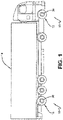
- FIG. 1 An exemplary embodiment of the sensor retaining system 10 for a vehicle tire of the present invention is presented in Figures 1 through 8D .
- one or more tires 12 supports a vehicle 14. While the vehicle 14 is depicted as a commercial truck, the invention is not to be so restricted. The principles of the invention find application in other vehicle categories, such as passenger vehicles, off-the-road vehicles and the like, in which vehicles may be supported by more or fewer tires than shown in Figure 1 .
- the tire 12 includes a pair of bead areas 16, each one of which is formed with a bead core 18 that is embedded in the respective bead areas.
- Each one of a pair of sidewalls 20 extends radially outwardly from a respective bead area 16 to a ground-contacting tread 22.
- the tread 22 is formed with multiple tread elements or tread blocks 32 and includes a radially outer surface 34.
- the tire 12 is reinforced by a carcass 24 that toroidally extends from one bead area 16 to the other bead area, as known to those skilled in the art.
- An innerliner 26 is formed on the inner or inside surface of the carcass 24.
- the tire 12 is mounted on the flange of a wheel or rim 36 ( Figure 1 ) as known in the art, forming an internal cavity 30.
- a sensor unit 28 is mounted to the tire 12.
- the sensor unit 28 detects certain real-time parameters of the tire 12, and preferably includes a pressure sensor to sense the inflation pressure within a cavity 30 of the tire, and a temperature sensor to sense the temperature of the tire and/or the temperature in the cavity.
- the sensor unit 28 preferably is a commercially available tire pressure monitoring system (TPMS) module or sensing unit.
- TPMS tire pressure monitoring system
- the sensor unit 28 preferably also includes a processor and memory to store tire identification (ID) information for each specific tire 12.
- the tire ID may include manufacturing information for the tire 12, including: the tire model; size information, such as rim size, width, and outer diameter; manufacturing location; manufacturing date; a treadcap code that includes or correlates to a compound identification; and a mold code that includes or correlates to a tread structure identification.
- the tire ID may also include a service history or other information to identify specific features and parameters of each tire 12.
- the sensor unit 28 preferably further includes an antenna for wirelessly transmitting measured parameters and tire ID data to a remote processor for analysis, such as a processor integrated into a vehicle electronic control unit and/or CAN bus.
- the sensor unit 28 preferably is mounted to the tire 12 using a container 38, which receives the sensor unit and is attached to the innerliner 26 by an adhesive.
- the container 38 is flexible and is formed of an elastomer or polymer. The sensor unit 28 is inserted into the container 38 through a sensor unit opening 40. Because the container 38 is formed of a flexible material, a wall 56 and lip 58 flex to allow insertion of the sensor unit 28, and then secure the sensor unit in the container.
- the sensor unit 28 includes a rigid housing 50 formed with a base 52.
- a pair of electrical contacts 54 are mounted on the base 52 and extend through the housing 50.
- a tread wear sensor 44 is disposed in an opening 42 that is formed in a selected tread element 32.
- An opening 46 is formed in a base 48 of the container 38, which aligns with the opening 42 to allow the tread wear sensor 44 to seat in the selected tread element 32 and extend into the container.
- a conductive wire 60 is disposed in the tread wear sensor 44.
- the wire 60 preferably is an insulated wire, but may be an uninsulated wire, depending on particular design considerations.
- the wire is formed in a U-shape and thus has proximal ends 62 and a distal end 64. The proximal ends 62 of the wire 60 extend to a bottom 68 of the tread wear sensor 44 to contact the electrical contacts 54 of the sensor unit 28.
- a continuous electrical circuit is formed by the wire 60 and the contact of each proximal wire end 62 with each respective electrical contact 54 of the sensor unit 28.
- the tread wear sensor 44 also wears.
- the distal end 64 of the wire 60 breaks, creating a break in the electrical circuit formed by the wire and the contact of each proximal wire end 62 with each respective sensor unit electrical contact 54.
- the sensor unit 28 senses the break in the electrical circuit, and wirelessly transmits a notice that the electrical circuit has broken and/or that the minimum recommended tread depth has been reached.
- the container 38 may not provide sufficient compression or holding force on the sensor unit 28 to maintain electrical contact between the tread wear sensor 44 and the sensor unit.
- the container 38 may allow excessive relative movement between the tread wear sensor 44 and the sensor unit 28, abrading the sensor unit electric contacts 54 and/or the tread wear sensor wire proximal ends 62.
- the sensor retaining system for a vehicle tire of the present invention 10 overcomes these disadvantages.
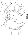
- the sensor retaining system 10 includes a cup 70.
- the cup 70 includes a base 72, which is formed with a central opening 74.
- the cup 70 also includes a sidewall 76 that extends radially from the base 72. The base 72 and the sidewall 76 cooperate to form a cup cavity 82.
- the central opening 74 in the base 72 aligns with the opening 46 formed in the container 38 and the opening 42 in the selected tread element 32.
- the tread wear sensor 44 extends through the central opening 74 in the base 72, through the container opening 46 and into the selected tread element opening 42.
- the bottom 68 of the tread wear sensor 44 and thus the proximal ends 62 of the wire 60 remain in the cup cavity 82.
- the sensor unit 28 is received and seats in the cup cavity 82, thereby ensuring that the electrical contacts 54 engage the proximal ends 62 of the wire 60.
- the cup 70 is formed of a rigid or semi-rigid material that exhibits compliance for compression, such as a plastic, elastomer, thermoplastic elastomer, or a metal. In this manner, the sidewall 76 of the cup 70 creates mechanical compression on the housing 50 of the sensor unit 28 to maintain a secure connection between the electrical contacts 54 and the proximal ends 62 of the wire 60.
- the cup is inserted into the flexible container 38. More particularly, because the container 38 is formed of a flexible material, the wall 56 and lip 58 flex to allow insertion of the cup 70 with the tread wear sensor 44 and the sensor unit 28 through the opening 40. Once the cup 70 is inserted into the container 38, the wall 56 and lip 58 engage the cup and the sensor unit 28 to secure them in the container. Thus, the tread wear sensor 44 and the sensor unit 28 are secured together by the cup 70, which is received and contained in the container 38 and affixed to the tire innerliner 26.
- the sidewall may be formed with an inwardly extending flange feature 78.
- the flange feature 78 may include any suitable cross section, such as a right-triangle cross section 78A, a semi-circular cross section 78B, or an isosceles triangle cross section 78C.
- the sidewall 76 of the plug 70 may be adapted based on particular design considerations to provide optimum compression on the sensor plug 26.
- the sidewall 76 may be a solid sidewall with a continuous flange feature 78.
- the sidewall 76 may be a solid wall with multiple discrete flange features 78.
- the sidewall 76 may be formed with a continuous flange feature 78 and one or more radially extending slots 80, which provide compliance of the sidewall to grip the housing 50 of the sensor unit 28.
- the sidewall 76 is formed with radially extending slots 80, preferably, four (4) slots are formed.
- the sidewall 76 may be formed with multiple discrete flange features 78, and one or more slots 80.
- the sensor retaining system for a vehicle tire 10 includes a plug 70 that provides a mechanical interlock to create a compression force on the sensor unit 28 and the tread wear sensor 44.
- the sensor retaining system 10 thus provides compression to maintain electrical contact between the sensor unit 28 and the tread wear sensor 44, and to reduce relative movement between the sensor unit and the tread wear sensor.
- the sensor retaining system 10 is durable and easy to install.
- the present invention also includes a method of forming a tire with a sensor retaining system 10.
- the method includes steps in accordance with the description that is presented above and shown in Figures 1 through 8D .
- the structure of the above-described sensor retaining system for a vehicle tire 10 may be altered or rearranged, or components or steps known to those skilled in the art omitted or added, without affecting the overall concept or operation of the invention.
- the container 38 and the cup 70 may be discrete units, or may be incorporated into a single integrated unit, without affecting the overall concept or operation of the invention.
Landscapes
- Engineering & Computer Science (AREA)
- Mechanical Engineering (AREA)
- Tires In General (AREA)
Applications Claiming Priority (2)
| Application Number | Priority Date | Filing Date | Title |
|---|---|---|---|
| US202063125447P | 2020-12-15 | 2020-12-15 | |
| US17/502,077 US11738604B2 (en) | 2020-12-15 | 2021-10-15 | Sensor retaining system for vehicle tire |
Publications (2)
| Publication Number | Publication Date |
|---|---|
| EP4015252A1 true EP4015252A1 (fr) | 2022-06-22 |
| EP4015252B1 EP4015252B1 (fr) | 2024-03-20 |
Family
ID=78820656
Family Applications (1)
| Application Number | Title | Priority Date | Filing Date |
|---|---|---|---|
| EP21211735.2A Active EP4015252B1 (fr) | 2020-12-15 | 2021-12-01 | Système de retenue de capteur de pneu de véhicule |
Country Status (2)
| Country | Link |
|---|---|
| US (1) | US11738604B2 (fr) |
| EP (1) | EP4015252B1 (fr) |
Cited By (2)
| Publication number | Priority date | Publication date | Assignee | Title |
|---|---|---|---|---|
| EP4197820A1 (fr) * | 2021-12-14 | 2023-06-21 | The Goodyear Tire & Rubber Company | Capteur d'usure de bande de roulement intégré et récipient tpms pour pneu |
| EP4474170A1 (fr) * | 2023-06-08 | 2024-12-11 | The Goodyear Tire & Rubber Company | Système et procédé de détection de port de bande de roulement de pneu |
Families Citing this family (1)
| Publication number | Priority date | Publication date | Assignee | Title |
|---|---|---|---|---|
| US11964515B2 (en) | 2020-12-15 | 2024-04-23 | The Goodyear Tire & Rubber Company | Integrated tread wear sensor and TPMS container for a tire |
Citations (3)
| Publication number | Priority date | Publication date | Assignee | Title |
|---|---|---|---|---|
| US9476789B2 (en) * | 2009-09-30 | 2016-10-25 | Compagnie Generale Des Etablissements Michelin | Sealed pressure-measuring member |
| WO2018047781A1 (fr) * | 2016-09-07 | 2018-03-15 | 株式会社デンソー | Capteur monté sur pneu |
| KR102124829B1 (ko) * | 2020-02-10 | 2020-06-22 | 유성원 | 타이어 마모 감지 장치 |
Family Cites Families (18)
| Publication number | Priority date | Publication date | Assignee | Title |
|---|---|---|---|---|
| US5971046A (en) | 1997-09-17 | 1999-10-26 | Bridgestone/Firestone, Inc. | Method and apparatus for bonding an active tag to a patch and a tire |
| DE19745734B4 (de) | 1997-10-16 | 2007-07-05 | Bayerische Motoren Werke Ag | Abriebsensor zur Erfassung der Profiltiefe eines Reifens von Kraftfahrzeugen |
| DE69916115T2 (de) | 1998-08-03 | 2009-10-01 | The Goodyear Tire & Rubber Co., Akron | Montage von transpondern in luftreifen |
| US6885291B1 (en) | 1999-11-15 | 2005-04-26 | The Goodyear Tire & Rubber Company | Mouting transponders and antennas in pneumatic tires |
| US6889153B2 (en) | 2001-08-09 | 2005-05-03 | Thomas Dietiker | System and method for a self-calibrating non-invasive sensor |
| FR2834934A1 (fr) * | 2002-01-21 | 2003-07-25 | Michelin Soc Tech | Procede et systemes de mesure de l'usure d'un pneumatique |
| DE20216290U1 (de) | 2002-10-23 | 2003-01-23 | Continental Aktiengesellschaft, 30165 Hannover | Fahrzeugreifen |
| US6854324B2 (en) * | 2002-12-20 | 2005-02-15 | The Goodyear Tire & Rubber Company | Tire monitoring apparatus |
| JP4316313B2 (ja) | 2003-07-09 | 2009-08-19 | 横浜ゴム株式会社 | タイヤ摩耗検知方法と装置、及び空気入りタイヤ |
| US7280036B2 (en) | 2005-05-04 | 2007-10-09 | Eric Adel Kafrawy | Detection and warning system |
| DE102007001279B4 (de) | 2007-01-08 | 2021-02-11 | Continental Reifen Deutschland Gmbh | Fahrzeugluftreifen mit einem Elektronikmodul |
| DE102010000003A1 (de) | 2010-01-05 | 2011-07-07 | Continental Reifen Deutschland GmbH, 30165 | Reifenmodul für Fahrzeugreifen |
| US9016118B2 (en) | 2010-12-22 | 2015-04-28 | Caterpillar Inc. | Mounting structure |
| US8596117B2 (en) | 2011-10-03 | 2013-12-03 | Bridgestone Americas Tire Operations, Llc | Attachment patch for mounting various devices |
| US9283817B2 (en) | 2011-11-22 | 2016-03-15 | The Goodyear Tire & Rubber Company | Stiffness enhanced tread |
| US9649889B2 (en) * | 2012-12-13 | 2017-05-16 | The Goodyear Tire & Rubber Company | Autonomous, plug-in wear or abrasion sensing system |
| US9352615B2 (en) | 2013-10-22 | 2016-05-31 | The Goodyear Tire & Rubber Company | Pneumatic tire with multi-tread cap |
| FR3077385B1 (fr) * | 2018-01-30 | 2020-06-05 | Continental Automotive France | Unite electronique de mesure de parametres de fonctionnement d'une roue de vehicule adaptee pour etre positionnee sur la face interne d'une bande de roulement d'un pneumatique |
-
2021
- 2021-10-15 US US17/502,077 patent/US11738604B2/en active Active
- 2021-12-01 EP EP21211735.2A patent/EP4015252B1/fr active Active
Patent Citations (3)
| Publication number | Priority date | Publication date | Assignee | Title |
|---|---|---|---|---|
| US9476789B2 (en) * | 2009-09-30 | 2016-10-25 | Compagnie Generale Des Etablissements Michelin | Sealed pressure-measuring member |
| WO2018047781A1 (fr) * | 2016-09-07 | 2018-03-15 | 株式会社デンソー | Capteur monté sur pneu |
| KR102124829B1 (ko) * | 2020-02-10 | 2020-06-22 | 유성원 | 타이어 마모 감지 장치 |
Cited By (3)
| Publication number | Priority date | Publication date | Assignee | Title |
|---|---|---|---|---|
| EP4197820A1 (fr) * | 2021-12-14 | 2023-06-21 | The Goodyear Tire & Rubber Company | Capteur d'usure de bande de roulement intégré et récipient tpms pour pneu |
| EP4474170A1 (fr) * | 2023-06-08 | 2024-12-11 | The Goodyear Tire & Rubber Company | Système et procédé de détection de port de bande de roulement de pneu |
| US12545059B2 (en) | 2023-06-08 | 2026-02-10 | The Goodyear Tire & Rubber Company | Systems and methods for tire treadwear sensing |
Also Published As
| Publication number | Publication date |
|---|---|
| US20220185031A1 (en) | 2022-06-16 |
| US11738604B2 (en) | 2023-08-29 |
| EP4015252B1 (fr) | 2024-03-20 |
Similar Documents
| Publication | Publication Date | Title |
|---|---|---|
| EP4015255B1 (fr) | Pneu doté d'un bouchon de polymère pour la détection d'usure de bande de roulement et son procédé de fabrication | |
| KR100948846B1 (ko) | 차량 주행동안 타이어를 감시하는 방법 및 시스템 | |
| US11964515B2 (en) | Integrated tread wear sensor and TPMS container for a tire | |
| US10935466B2 (en) | Integrated tire sensor and reader system | |
| EP4015252B1 (fr) | Système de retenue de capteur de pneu de véhicule | |
| EP4015251B1 (fr) | Pneu doté d'un bouchon de capteur d'usure de bande de roulement | |
| EP4015256B1 (fr) | Système de conteneur de capteurs de pneus | |
| JP4268363B2 (ja) | 空気入りタイヤ及びタイヤ変形検出方法 | |
| EP4197820B1 (fr) | Capteur d'usure de bande de roulement intégré et récipient tpms pour pneu | |
| US20230182510A1 (en) | Systems and methods for tire tread wear sensing and electrostatic discharge | |
| EP4480719B1 (fr) | Détection d'usure irrégulière ou irrégulière | |
| EP4706996A1 (fr) | Pneu, procédé et système intégrant un capteur au niveau d'une zone de transition de bride de jante d'un pneu par formation de cavité | |
| CN119159931A (zh) | 不均匀和不规则胎面磨损的检测 | |
| EP4477432B1 (fr) | Pneu avec un ensemble de capteurs imprimés | |
| CN121625677A (zh) | 在制造过程期间将传感器集成到轮胎的轮辋凸缘过渡区域中的系统和方法 | |
| CN119142076A (zh) | 带有一组打印传感器的轮胎 |
Legal Events
| Date | Code | Title | Description |
|---|---|---|---|
| PUAI | Public reference made under article 153(3) epc to a published international application that has entered the european phase |
Free format text: ORIGINAL CODE: 0009012 |
|
| STAA | Information on the status of an ep patent application or granted ep patent |
Free format text: STATUS: THE APPLICATION HAS BEEN PUBLISHED |
|
| AK | Designated contracting states |
Kind code of ref document: A1 Designated state(s): AL AT BE BG CH CY CZ DE DK EE ES FI FR GB GR HR HU IE IS IT LI LT LU LV MC MK MT NL NO PL PT RO RS SE SI SK SM TR |
|
| STAA | Information on the status of an ep patent application or granted ep patent |
Free format text: STATUS: REQUEST FOR EXAMINATION WAS MADE |
|
| 17P | Request for examination filed |
Effective date: 20221222 |
|
| RBV | Designated contracting states (corrected) |
Designated state(s): AL AT BE BG CH CY CZ DE DK EE ES FI FR GB GR HR HU IE IS IT LI LT LU LV MC MK MT NL NO PL PT RO RS SE SI SK SM TR |
|
| GRAP | Despatch of communication of intention to grant a patent |
Free format text: ORIGINAL CODE: EPIDOSNIGR1 |
|
| STAA | Information on the status of an ep patent application or granted ep patent |
Free format text: STATUS: GRANT OF PATENT IS INTENDED |
|
| INTG | Intention to grant announced |
Effective date: 20231012 |
|
| GRAS | Grant fee paid |
Free format text: ORIGINAL CODE: EPIDOSNIGR3 |
|
| GRAA | (expected) grant |
Free format text: ORIGINAL CODE: 0009210 |
|
| STAA | Information on the status of an ep patent application or granted ep patent |
Free format text: STATUS: THE PATENT HAS BEEN GRANTED |
|
| AK | Designated contracting states |
Kind code of ref document: B1 Designated state(s): AL AT BE BG CH CY CZ DE DK EE ES FI FR GB GR HR HU IE IS IT LI LT LU LV MC MK MT NL NO PL PT RO RS SE SI SK SM TR |
|
| REG | Reference to a national code |
Ref country code: GB Ref legal event code: FG4D |
|
| REG | Reference to a national code |
Ref country code: CH Ref legal event code: EP |
|
| REG | Reference to a national code |
Ref country code: IE Ref legal event code: FG4D |
|
| REG | Reference to a national code |
Ref country code: DE Ref legal event code: R096 Ref document number: 602021010637 Country of ref document: DE |
|
| PG25 | Lapsed in a contracting state [announced via postgrant information from national office to epo] |
Ref country code: LT Free format text: LAPSE BECAUSE OF FAILURE TO SUBMIT A TRANSLATION OF THE DESCRIPTION OR TO PAY THE FEE WITHIN THE PRESCRIBED TIME-LIMIT Effective date: 20240320 |
|
| REG | Reference to a national code |
Ref country code: LT Ref legal event code: MG9D |
|
| PG25 | Lapsed in a contracting state [announced via postgrant information from national office to epo] |
Ref country code: GR Free format text: LAPSE BECAUSE OF FAILURE TO SUBMIT A TRANSLATION OF THE DESCRIPTION OR TO PAY THE FEE WITHIN THE PRESCRIBED TIME-LIMIT Effective date: 20240621 |
|
| PG25 | Lapsed in a contracting state [announced via postgrant information from national office to epo] |
Ref country code: HR Free format text: LAPSE BECAUSE OF FAILURE TO SUBMIT A TRANSLATION OF THE DESCRIPTION OR TO PAY THE FEE WITHIN THE PRESCRIBED TIME-LIMIT Effective date: 20240320 Ref country code: RS Free format text: LAPSE BECAUSE OF FAILURE TO SUBMIT A TRANSLATION OF THE DESCRIPTION OR TO PAY THE FEE WITHIN THE PRESCRIBED TIME-LIMIT Effective date: 20240620 |
|
| REG | Reference to a national code |
Ref country code: NL Ref legal event code: MP Effective date: 20240320 |
|
| PG25 | Lapsed in a contracting state [announced via postgrant information from national office to epo] |
Ref country code: RS Free format text: LAPSE BECAUSE OF FAILURE TO SUBMIT A TRANSLATION OF THE DESCRIPTION OR TO PAY THE FEE WITHIN THE PRESCRIBED TIME-LIMIT Effective date: 20240620 Ref country code: NO Free format text: LAPSE BECAUSE OF FAILURE TO SUBMIT A TRANSLATION OF THE DESCRIPTION OR TO PAY THE FEE WITHIN THE PRESCRIBED TIME-LIMIT Effective date: 20240620 Ref country code: LT Free format text: LAPSE BECAUSE OF FAILURE TO SUBMIT A TRANSLATION OF THE DESCRIPTION OR TO PAY THE FEE WITHIN THE PRESCRIBED TIME-LIMIT Effective date: 20240320 Ref country code: HR Free format text: LAPSE BECAUSE OF FAILURE TO SUBMIT A TRANSLATION OF THE DESCRIPTION OR TO PAY THE FEE WITHIN THE PRESCRIBED TIME-LIMIT Effective date: 20240320 Ref country code: GR Free format text: LAPSE BECAUSE OF FAILURE TO SUBMIT A TRANSLATION OF THE DESCRIPTION OR TO PAY THE FEE WITHIN THE PRESCRIBED TIME-LIMIT Effective date: 20240621 Ref country code: FI Free format text: LAPSE BECAUSE OF FAILURE TO SUBMIT A TRANSLATION OF THE DESCRIPTION OR TO PAY THE FEE WITHIN THE PRESCRIBED TIME-LIMIT Effective date: 20240320 Ref country code: BG Free format text: LAPSE BECAUSE OF FAILURE TO SUBMIT A TRANSLATION OF THE DESCRIPTION OR TO PAY THE FEE WITHIN THE PRESCRIBED TIME-LIMIT Effective date: 20240320 |
|
| REG | Reference to a national code |
Ref country code: AT Ref legal event code: MK05 Ref document number: 1667526 Country of ref document: AT Kind code of ref document: T Effective date: 20240320 |
|
| PG25 | Lapsed in a contracting state [announced via postgrant information from national office to epo] |
Ref country code: SE Free format text: LAPSE BECAUSE OF FAILURE TO SUBMIT A TRANSLATION OF THE DESCRIPTION OR TO PAY THE FEE WITHIN THE PRESCRIBED TIME-LIMIT Effective date: 20240320 Ref country code: LV Free format text: LAPSE BECAUSE OF FAILURE TO SUBMIT A TRANSLATION OF THE DESCRIPTION OR TO PAY THE FEE WITHIN THE PRESCRIBED TIME-LIMIT Effective date: 20240320 |
|
| PG25 | Lapsed in a contracting state [announced via postgrant information from national office to epo] |
Ref country code: NL Free format text: LAPSE BECAUSE OF FAILURE TO SUBMIT A TRANSLATION OF THE DESCRIPTION OR TO PAY THE FEE WITHIN THE PRESCRIBED TIME-LIMIT Effective date: 20240320 |
|
| PG25 | Lapsed in a contracting state [announced via postgrant information from national office to epo] |
Ref country code: NL Free format text: LAPSE BECAUSE OF FAILURE TO SUBMIT A TRANSLATION OF THE DESCRIPTION OR TO PAY THE FEE WITHIN THE PRESCRIBED TIME-LIMIT Effective date: 20240320 |
|
| PG25 | Lapsed in a contracting state [announced via postgrant information from national office to epo] |
Ref country code: IS Free format text: LAPSE BECAUSE OF FAILURE TO SUBMIT A TRANSLATION OF THE DESCRIPTION OR TO PAY THE FEE WITHIN THE PRESCRIBED TIME-LIMIT Effective date: 20240720 |
|
| PG25 | Lapsed in a contracting state [announced via postgrant information from national office to epo] |
Ref country code: PT Free format text: LAPSE BECAUSE OF FAILURE TO SUBMIT A TRANSLATION OF THE DESCRIPTION OR TO PAY THE FEE WITHIN THE PRESCRIBED TIME-LIMIT Effective date: 20240722 Ref country code: SM Free format text: LAPSE BECAUSE OF FAILURE TO SUBMIT A TRANSLATION OF THE DESCRIPTION OR TO PAY THE FEE WITHIN THE PRESCRIBED TIME-LIMIT Effective date: 20240320 |
|
| PG25 | Lapsed in a contracting state [announced via postgrant information from national office to epo] |
Ref country code: ES Free format text: LAPSE BECAUSE OF FAILURE TO SUBMIT A TRANSLATION OF THE DESCRIPTION OR TO PAY THE FEE WITHIN THE PRESCRIBED TIME-LIMIT Effective date: 20240320 |
|
| PG25 | Lapsed in a contracting state [announced via postgrant information from national office to epo] |
Ref country code: EE Free format text: LAPSE BECAUSE OF FAILURE TO SUBMIT A TRANSLATION OF THE DESCRIPTION OR TO PAY THE FEE WITHIN THE PRESCRIBED TIME-LIMIT Effective date: 20240320 Ref country code: CZ Free format text: LAPSE BECAUSE OF FAILURE TO SUBMIT A TRANSLATION OF THE DESCRIPTION OR TO PAY THE FEE WITHIN THE PRESCRIBED TIME-LIMIT Effective date: 20240320 |
|
| PG25 | Lapsed in a contracting state [announced via postgrant information from national office to epo] |
Ref country code: AT Free format text: LAPSE BECAUSE OF FAILURE TO SUBMIT A TRANSLATION OF THE DESCRIPTION OR TO PAY THE FEE WITHIN THE PRESCRIBED TIME-LIMIT Effective date: 20240320 |
|
| PG25 | Lapsed in a contracting state [announced via postgrant information from national office to epo] |
Ref country code: PL Free format text: LAPSE BECAUSE OF FAILURE TO SUBMIT A TRANSLATION OF THE DESCRIPTION OR TO PAY THE FEE WITHIN THE PRESCRIBED TIME-LIMIT Effective date: 20240320 |
|
| PG25 | Lapsed in a contracting state [announced via postgrant information from national office to epo] |
Ref country code: SK Free format text: LAPSE BECAUSE OF FAILURE TO SUBMIT A TRANSLATION OF THE DESCRIPTION OR TO PAY THE FEE WITHIN THE PRESCRIBED TIME-LIMIT Effective date: 20240320 |
|
| PG25 | Lapsed in a contracting state [announced via postgrant information from national office to epo] |
Ref country code: SM Free format text: LAPSE BECAUSE OF FAILURE TO SUBMIT A TRANSLATION OF THE DESCRIPTION OR TO PAY THE FEE WITHIN THE PRESCRIBED TIME-LIMIT Effective date: 20240320 Ref country code: SK Free format text: LAPSE BECAUSE OF FAILURE TO SUBMIT A TRANSLATION OF THE DESCRIPTION OR TO PAY THE FEE WITHIN THE PRESCRIBED TIME-LIMIT Effective date: 20240320 Ref country code: RO Free format text: LAPSE BECAUSE OF FAILURE TO SUBMIT A TRANSLATION OF THE DESCRIPTION OR TO PAY THE FEE WITHIN THE PRESCRIBED TIME-LIMIT Effective date: 20240320 Ref country code: PT Free format text: LAPSE BECAUSE OF FAILURE TO SUBMIT A TRANSLATION OF THE DESCRIPTION OR TO PAY THE FEE WITHIN THE PRESCRIBED TIME-LIMIT Effective date: 20240722 Ref country code: PL Free format text: LAPSE BECAUSE OF FAILURE TO SUBMIT A TRANSLATION OF THE DESCRIPTION OR TO PAY THE FEE WITHIN THE PRESCRIBED TIME-LIMIT Effective date: 20240320 Ref country code: IS Free format text: LAPSE BECAUSE OF FAILURE TO SUBMIT A TRANSLATION OF THE DESCRIPTION OR TO PAY THE FEE WITHIN THE PRESCRIBED TIME-LIMIT Effective date: 20240720 Ref country code: ES Free format text: LAPSE BECAUSE OF FAILURE TO SUBMIT A TRANSLATION OF THE DESCRIPTION OR TO PAY THE FEE WITHIN THE PRESCRIBED TIME-LIMIT Effective date: 20240320 Ref country code: EE Free format text: LAPSE BECAUSE OF FAILURE TO SUBMIT A TRANSLATION OF THE DESCRIPTION OR TO PAY THE FEE WITHIN THE PRESCRIBED TIME-LIMIT Effective date: 20240320 Ref country code: CZ Free format text: LAPSE BECAUSE OF FAILURE TO SUBMIT A TRANSLATION OF THE DESCRIPTION OR TO PAY THE FEE WITHIN THE PRESCRIBED TIME-LIMIT Effective date: 20240320 Ref country code: AT Free format text: LAPSE BECAUSE OF FAILURE TO SUBMIT A TRANSLATION OF THE DESCRIPTION OR TO PAY THE FEE WITHIN THE PRESCRIBED TIME-LIMIT Effective date: 20240320 |
|
| REG | Reference to a national code |
Ref country code: DE Ref legal event code: R097 Ref document number: 602021010637 Country of ref document: DE |
|
| PG25 | Lapsed in a contracting state [announced via postgrant information from national office to epo] |
Ref country code: DK Free format text: LAPSE BECAUSE OF FAILURE TO SUBMIT A TRANSLATION OF THE DESCRIPTION OR TO PAY THE FEE WITHIN THE PRESCRIBED TIME-LIMIT Effective date: 20240320 |
|
| PLBE | No opposition filed within time limit |
Free format text: ORIGINAL CODE: 0009261 |
|
| STAA | Information on the status of an ep patent application or granted ep patent |
Free format text: STATUS: NO OPPOSITION FILED WITHIN TIME LIMIT |
|
| PG25 | Lapsed in a contracting state [announced via postgrant information from national office to epo] |
Ref country code: DK Free format text: LAPSE BECAUSE OF FAILURE TO SUBMIT A TRANSLATION OF THE DESCRIPTION OR TO PAY THE FEE WITHIN THE PRESCRIBED TIME-LIMIT Effective date: 20240320 |
|
| 26N | No opposition filed |
Effective date: 20241223 |
|
| PG25 | Lapsed in a contracting state [announced via postgrant information from national office to epo] |
Ref country code: SI Free format text: LAPSE BECAUSE OF FAILURE TO SUBMIT A TRANSLATION OF THE DESCRIPTION OR TO PAY THE FEE WITHIN THE PRESCRIBED TIME-LIMIT Effective date: 20240320 |
|
| PG25 | Lapsed in a contracting state [announced via postgrant information from national office to epo] |
Ref country code: MC Free format text: LAPSE BECAUSE OF FAILURE TO SUBMIT A TRANSLATION OF THE DESCRIPTION OR TO PAY THE FEE WITHIN THE PRESCRIBED TIME-LIMIT Effective date: 20240320 |
|
| REG | Reference to a national code |
Ref country code: CH Ref legal event code: PL |
|
| PG25 | Lapsed in a contracting state [announced via postgrant information from national office to epo] |
Ref country code: LU Free format text: LAPSE BECAUSE OF NON-PAYMENT OF DUE FEES Effective date: 20241201 |
|
| REG | Reference to a national code |
Ref country code: BE Ref legal event code: MM Effective date: 20241231 |
|
| PG25 | Lapsed in a contracting state [announced via postgrant information from national office to epo] |
Ref country code: BE Free format text: LAPSE BECAUSE OF NON-PAYMENT OF DUE FEES Effective date: 20241231 |
|
| PG25 | Lapsed in a contracting state [announced via postgrant information from national office to epo] |
Ref country code: CH Free format text: LAPSE BECAUSE OF NON-PAYMENT OF DUE FEES Effective date: 20241231 |
|
| PG25 | Lapsed in a contracting state [announced via postgrant information from national office to epo] |
Ref country code: IE Free format text: LAPSE BECAUSE OF NON-PAYMENT OF DUE FEES Effective date: 20241201 |
|
| PGFP | Annual fee paid to national office [announced via postgrant information from national office to epo] |
Ref country code: DE Payment date: 20251126 Year of fee payment: 5 |
|
| PGFP | Annual fee paid to national office [announced via postgrant information from national office to epo] |
Ref country code: GB Payment date: 20251120 Year of fee payment: 5 |
|
| PGFP | Annual fee paid to national office [announced via postgrant information from national office to epo] |
Ref country code: IT Payment date: 20251119 Year of fee payment: 5 |
|
| PGFP | Annual fee paid to national office [announced via postgrant information from national office to epo] |
Ref country code: FR Payment date: 20251120 Year of fee payment: 5 |
|
| PG25 | Lapsed in a contracting state [announced via postgrant information from national office to epo] |
Ref country code: CY Free format text: LAPSE BECAUSE OF FAILURE TO SUBMIT A TRANSLATION OF THE DESCRIPTION OR TO PAY THE FEE WITHIN THE PRESCRIBED TIME-LIMIT; INVALID AB INITIO Effective date: 20211201 |