EP4015254B1 - Pneumatique à bourrelet perfectionné - Google Patents
Pneumatique à bourrelet perfectionné Download PDFInfo
- Publication number
- EP4015254B1 EP4015254B1 EP21212086.9A EP21212086A EP4015254B1 EP 4015254 B1 EP4015254 B1 EP 4015254B1 EP 21212086 A EP21212086 A EP 21212086A EP 4015254 B1 EP4015254 B1 EP 4015254B1
- Authority
- EP
- European Patent Office
- Prior art keywords
- bead core
- pneumatic tire
- annular
- sheath wires
- annular layer
- Prior art date
- Legal status (The legal status is an assumption and is not a legal conclusion. Google has not performed a legal analysis and makes no representation as to the accuracy of the status listed.)
- Active
Links
Images

Classifications
-
- B—PERFORMING OPERATIONS; TRANSPORTING
- B60—VEHICLES IN GENERAL
- B60C—VEHICLE TYRES; TYRE INFLATION; TYRE CHANGING; CONNECTING VALVES TO INFLATABLE ELASTIC BODIES IN GENERAL; DEVICES OR ARRANGEMENTS RELATED TO TYRES
- B60C15/00—Tyre beads, e.g. ply turn-up or overlap
- B60C15/04—Bead cores
-
- B—PERFORMING OPERATIONS; TRANSPORTING
- B60—VEHICLES IN GENERAL
- B60C—VEHICLE TYRES; TYRE INFLATION; TYRE CHANGING; CONNECTING VALVES TO INFLATABLE ELASTIC BODIES IN GENERAL; DEVICES OR ARRANGEMENTS RELATED TO TYRES
- B60C15/00—Tyre beads, e.g. ply turn-up or overlap
- B60C15/06—Flipper strips, fillers, or chafing strips and reinforcing layers for the construction of the bead
- B60C15/0603—Flipper strips, fillers, or chafing strips and reinforcing layers for the construction of the bead characterised by features of the bead filler or apex
-
- B—PERFORMING OPERATIONS; TRANSPORTING
- B60—VEHICLES IN GENERAL
- B60C—VEHICLE TYRES; TYRE INFLATION; TYRE CHANGING; CONNECTING VALVES TO INFLATABLE ELASTIC BODIES IN GENERAL; DEVICES OR ARRANGEMENTS RELATED TO TYRES
- B60C15/00—Tyre beads, e.g. ply turn-up or overlap
- B60C15/06—Flipper strips, fillers, or chafing strips and reinforcing layers for the construction of the bead
-
- B—PERFORMING OPERATIONS; TRANSPORTING
- B60—VEHICLES IN GENERAL
- B60C—VEHICLE TYRES; TYRE INFLATION; TYRE CHANGING; CONNECTING VALVES TO INFLATABLE ELASTIC BODIES IN GENERAL; DEVICES OR ARRANGEMENTS RELATED TO TYRES
- B60C15/00—Tyre beads, e.g. ply turn-up or overlap
- B60C15/06—Flipper strips, fillers, or chafing strips and reinforcing layers for the construction of the bead
- B60C15/0628—Flipper strips, fillers, or chafing strips and reinforcing layers for the construction of the bead comprising a bead reinforcing layer
- B60C15/0632—Flipper strips, fillers, or chafing strips and reinforcing layers for the construction of the bead comprising a bead reinforcing layer using flippers in contact with and wrapped around the bead core and, at least partially, in contact with the bead filler
-
- B—PERFORMING OPERATIONS; TRANSPORTING
- B60—VEHICLES IN GENERAL
- B60C—VEHICLE TYRES; TYRE INFLATION; TYRE CHANGING; CONNECTING VALVES TO INFLATABLE ELASTIC BODIES IN GENERAL; DEVICES OR ARRANGEMENTS RELATED TO TYRES
- B60C15/00—Tyre beads, e.g. ply turn-up or overlap
- B60C15/04—Bead cores
- B60C2015/042—Bead cores characterised by the material of the core, e.g. alloy
-
- B—PERFORMING OPERATIONS; TRANSPORTING
- B60—VEHICLES IN GENERAL
- B60C—VEHICLE TYRES; TYRE INFLATION; TYRE CHANGING; CONNECTING VALVES TO INFLATABLE ELASTIC BODIES IN GENERAL; DEVICES OR ARRANGEMENTS RELATED TO TYRES
- B60C15/00—Tyre beads, e.g. ply turn-up or overlap
- B60C15/04—Bead cores
- B60C2015/044—Bead cores characterised by a wrapping layer
-
- B—PERFORMING OPERATIONS; TRANSPORTING
- B60—VEHICLES IN GENERAL
- B60C—VEHICLE TYRES; TYRE INFLATION; TYRE CHANGING; CONNECTING VALVES TO INFLATABLE ELASTIC BODIES IN GENERAL; DEVICES OR ARRANGEMENTS RELATED TO TYRES
- B60C15/00—Tyre beads, e.g. ply turn-up or overlap
- B60C15/04—Bead cores
- B60C2015/046—Cable cores, i.e. cores made-up of twisted wires
-
- B—PERFORMING OPERATIONS; TRANSPORTING
- B60—VEHICLES IN GENERAL
- B60C—VEHICLE TYRES; TYRE INFLATION; TYRE CHANGING; CONNECTING VALVES TO INFLATABLE ELASTIC BODIES IN GENERAL; DEVICES OR ARRANGEMENTS RELATED TO TYRES
- B60C2200/00—Tyres specially adapted for particular applications
- B60C2200/02—Tyres specially adapted for particular applications for aircrafts
-
- B—PERFORMING OPERATIONS; TRANSPORTING
- B60—VEHICLES IN GENERAL
- B60C—VEHICLE TYRES; TYRE INFLATION; TYRE CHANGING; CONNECTING VALVES TO INFLATABLE ELASTIC BODIES IN GENERAL; DEVICES OR ARRANGEMENTS RELATED TO TYRES
- B60C2200/00—Tyres specially adapted for particular applications
- B60C2200/06—Tyres specially adapted for particular applications for heavy duty vehicles
Definitions
- the invention relates in general to pneumatic tires, and more particularly to a bead construction for heavy duty vehicles such as aircraft or trucks.
- Annular tensile members are designed to securely hold the tire on the rim during use.
- the tire beads provide a radially inner portion between the bead core and the rim that is radially compressed, and as this portion is compressed, the bead core is placed in tension. Radial compression occurs as the tire is mounted on a tapered rim seat by the action of the internal pressure of the tire pushing the bead axially outwardly toward the vertical bead flange.
- WO 2019/240101 A1 and WO 2013/282599 A1 each disclose a tire in accordance with the preamble of claim 1.
- the invention relates to a tire in accordance with claim 1.
- the tire is a radial tire, more preferably a radial aircraft tire.
- the invention provides in a first preferred aspect a pneumatic radial tire having a bead portion provided therein with a bead core, and a first layer of a plurality of sheath wires surrounding the bead core, and a second layer formed of a plurality of sheath wires surrounding the first layer, wherein the sheath wires of the second layer have a diameter less than the sheath wires of the first layer.
- Bead means generally that part of the tire comprising an annular tensile member, the radially inner beads are associated with holding the tire to the rim being wrapped by ply cords and shaped, with or without other reinforcement elements such as flippers, chippers, apexes or fillers, toe guards and chafers.
- “Flipper” means a reinforced fabric wrapped about the bead core.
- Ring and radially mean directions radially toward or away from the axis of rotation of the tire.
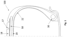
- FIG. 1 a cross-sectional view of one half of a radial ply tire 100 is shown.
- the tire 100 as illustrated, is a construction for use as an aircraft tire.
- the tire 100 by way of example is a radial aircraft tire exposed to high internal pressures and tremendous loads.
- Other such tires such as earthmover, truck and farm tires are also ideally suited for using the bead core of the present invention.
- the tire 100 is a radial ply tire having air imperious inner liner 22 which contains fluid or air under pressure.
- Radially outward of the inner liner 22 are one or more radial plies 20.
- Each ply 20 extends from an annular tensile member commonly referred to as a bead core 30.
- the plies 20 are anchored about the bead core 30 either turning axially out and up forming a ply turnup or alternately turning axially in and under the bead core 30.
- Radially above the bead core 30 is an optional rubber apex.
- a belt package 50 comprising a plurality of belt reinforcing layers, each layer is reinforced with parallel reinforcement cords.
- a top belt layer is shown radially outward of the belt layers 50.
- Above the belt is a tread 18 as shown, the tread 18 has a plurality of optional circumferentially continuous grooves 17.
- the tire structure 100 as mentioned is an example of one type of tire structures that can utilize the bead core 30 of the present invention. Although the tire 100 as shown is an aircraft tire structure, the invention is usable in any highly loaded heavy-duty tire structure.
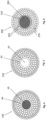
- the central core 33 is shown may optionally be a single wire or rod wound at 360 degree, wherein the ends of the wire are secured together to form one continuous hoop or central core 33.
- the central core 33 preferably has a diameter A in the range of 3 mm to 20 mm, and more preferably in the range of 5 to 15 mm.
- the cross-sectional shape of the central core is a solid circle.
- the central core 33 is preferably made of an alloy of aluminum, or other lightweight metal alloy such as magnesium, titanium, or any metal alloy having a weight less than steel.
- a metal central core is used, it is made of aluminum or an aluminum alloy which has superb strength ratios while maintaining excellent ductility.
- the central core may also be made of a nonmetal material such aramid, carbon fiber, or plastic resin.
- the central core 33 is wrapped by a first annular row of inner sheath wires 35.
- the diameter of the wires of the inner sheath wires 35 are the same, and range in size from 1.5 mm to 3 mm, and more preferably, in the range of 1.8 mm to 2.5 mm.
- the wires 35 of the sheath layers are steel that are helically or spirally wound about the central core 33.
- the bead core 30 further includes one or more annular rows of outer sheath layers 37.
- the wires in the outer annular row have a smaller diameter C than the diameter B of the wires in the inner sheath layers.
- the diameter C of the wires of the outer sheath layer 37 are the same, and range in size from 1.5 mm to 2.5 mm or range in size from 1 mm to 2 mm.
- a flipper 60 Wrapped around the entire bead core is a flipper 60, having an axially inner leg 62 and an axially outer leg 64.
- the flipper 60 is formed from a reinforced fabric wrapped about the bead core such as nylon or polyester.
- the reinforcement cords of the flipper material preferably have a 840 dtex/2, or a 1260 dtex/2, or a 1260 dtex/3, a 1890 dtex/2 and a 1890 dtex/3 nylon cord construction.
- the flipper material is nylon 6/6.
- FIG. 4 illustrates a second embodiment of a bead core 140 of the present invention.
- the second embodiment is the same as FIG. 3 , except for the following differences.
- the central core 40 has a cross-sectional shape of an annular tube, wherein the interior portion 45 of the annular tube is filled with a filler.
- the annular tube may be metal, aramid, nylon, carbon fiber or plastic.
- the metal is preferably aluminum or steel.
- the filler may be metal, plastic, carbon fiber or plastic.
- FIG. 5 a third embodiment of a bead core 240 is shown, which is the same as the bead core of FIG. 5 except for the following differences.
- the interior portion 45 of the central core is filled with air (i.e., its empty except for air).
- FIG. 6 illustrates a bead core 300 not being in accordance with the present invention.
- the central core 310 is formed of an annular tube 320, wherein the interior of the tube 320 may be filled with a filler or unfilled (with air).
- the annular tube 310 may be metal, aramid, nylon, carbon fiber or plastic.
- the metal is preferably aluminum or steel.
- the filler may be metal, plastic, carbon fiber or aramid.
- the diameter of the wires of the inner row 350 are the same, and range in size from 1.5 mm to 3 mm, and more preferably, in the range of 1.8 mm to 2.5 mm.
- the bead core 300 further has one radially outer row 370 of larger diameter wires, wherein the range of the diameters range from 1 mm to 2.5 mm, more preferably from 1 mm to 2 mm or from 1.5 mm to 2.5 mm.
- the entire bead core is coated in an adhesive rubber layer and then a textile ply cord is helically wrapped around the bead core.
- the sheath wires in the second annular layer 37, 370 preferably have a diameter at least 0.2 mm or at least 0.5 mm less than the diameter of the sheath wires in the first annular layer 35, 350.
Landscapes
- Engineering & Computer Science (AREA)
- Mechanical Engineering (AREA)
- Tires In General (AREA)
Claims (13)
- Bandage pneumatique qui possède une portion faisant office de talon, prévue dans le premier cité, qui comprend une tringle de talon (30, 140, 240, 300), la tringle de talon (30, 140, 240, 300) possédant une portion centrale de tringle de talon (33, 40, 310), une première couche annulaire (35, 350) constituée par un certain nombre de fils munis d'une gaine, qui entourent la portion centrale de tringle de talon (33, 40, 310), lesdits plusieurs fils munis d'une gaine dans ladite première couche annulaire (35, 350) possédant tous le même diamètre qui se situe dans une plage allant de 1,5 à 3 mm, et une deuxième couche annulaire (37, 370) formée par un certain nombre de fils munis d'une gaine, qui entourent la première couche annulaire (35, 350), lesdits plusieurs fils munis d'une gaine dans ladite deuxième couche annulaire (37, 370) possédant tous le même diamètre qui se situe dans une plage allant de 1 à 2,5 mm ; dans lequel les fils munis d'une gaine de la deuxième couche annulaire (37, 370) possèdent un diamètre inférieur au diamètre des fils munis d'une gaine de la première couche annulaire (35, 350), caractérisé en ce que l'on trouve un total de n rangées annulaires de fils munis d'une gaine dans la première couche annulaire (35, 350) et un total de n-1 rangées de fils munis d'une gaine dans la deuxième couche annulaire (37, 370), n représentant un nombre entier.
- Bandage pneumatique selon la revendication 1, dans lequel le diamètre des fils munis d'une gaine de la première couche annulaire (35, 350) se situe dans la plage allant de 1,8 à 2,5 mm.
- Bandage pneumatique selon la revendication 1 ou 2, dans lequel le diamètre des fils munis d'une gaine de la deuxième couche annulaire (37, 370) se situe dans la plage allant de 1 mm à 2 mm ou de 1,5 mm à 2,5 mm.
- Bandage pneumatique selon au moins une des revendications précédentes, dans lequel la configuration en section transversale de la tringle de talon (30, 140, 240, 300) prend la forme d'un cercle.
- Bandage pneumatique selon la revendication 4, dans lequel le cercle est formé par la première et la deuxième couches annulaires et la portion centrale de la tringle de talon (33, 40, 310) est une portion creuse ou une portion de forme tubulaire.
- Bandage pneumatique selon la revendication 4, dans lequel l'intérieur du cercle est rempli avec un métal, un non métal, de l'aramide, des fibres de carbone, une matière de charge en plastique ou est rempli avec de l'air.
- Bandage pneumatique selon au moins une des revendications précédentes, dans lequel la configuration en section transversale de la portion centrale de la tringle de talon (33, 40, 310) prend la forme d'un cercle.
- Bandage pneumatique selon au moins une des revendications précédentes, dans lequel la tringle de talon (30, 140, 240, 300) comprend une matière qui est choisie parmi le groupe constitué par le titane, l'aluminium, le magnésium ou un autre alliage métallique ou bien est réalisée à partir d'une telle matière.
- Bandage pneumatique selon au moins une des revendications précédentes, dans lequel la tringle de talon (30, 140, 240, 300) comprend une matière qui est choisie parmi le groupe constitué par l'aramide, des fibres de carbone, une matière plastique ou une autre matière non métallique ou bien est réalisée à partir d'une telle matière.
- Bandage pneumatique selon au moins une des revendications précédentes, dans lequel on prévoit deux ou trois rangées annulaires de fils munis d'une gaine dans la première couche annulaire (35, 350).
- Bandage pneumatique selon au moins une des revendications précédentes, dans lequel on prévoit une ou deux rangées annulaires de fils munis d'une gaine dans la deuxième couche annulaire (37, 370).
- Bandage pneumatique selon au moins une des revendications précédentes, dans lequel la portion centrale de la tringle de talon (33, 40, 310) possède un diamètre (A) qui se situe dans la plage allant de 3 mm à 20 mm, de préférence dans la plage allant de 5 à 15 mm.
- Bandage pneumatique selon au moins une des revendications précédentes, dans lequel la tringle de talon (30, 140, 240, 300) est recouverte d'une couche adhésive en caoutchouc et, de manière facultative dans lequel une nappe est enroulée de manière hélicoïdale autour de la tringle de talon (30, 140, 240, 300) et de la couche adhésive caoutchouc.
Applications Claiming Priority (1)
| Application Number | Priority Date | Filing Date | Title |
|---|---|---|---|
| US17/124,009 US20220185034A1 (en) | 2020-12-16 | 2020-12-16 | Tire with improved bead structure |
Publications (2)
| Publication Number | Publication Date |
|---|---|
| EP4015254A1 EP4015254A1 (fr) | 2022-06-22 |
| EP4015254B1 true EP4015254B1 (fr) | 2024-10-16 |
Family
ID=78821568
Family Applications (1)
| Application Number | Title | Priority Date | Filing Date |
|---|---|---|---|
| EP21212086.9A Active EP4015254B1 (fr) | 2020-12-16 | 2021-12-02 | Pneumatique à bourrelet perfectionné |
Country Status (4)
| Country | Link |
|---|---|
| US (1) | US20220185034A1 (fr) |
| EP (1) | EP4015254B1 (fr) |
| JP (1) | JP2022095554A (fr) |
| CN (1) | CN114633587A (fr) |
Families Citing this family (3)
| Publication number | Priority date | Publication date | Assignee | Title |
|---|---|---|---|---|
| CN116653504B (zh) * | 2023-06-26 | 2026-03-10 | 青岛双星轮胎工业有限公司 | 一种子午线轮胎及其应用 |
| CN117021845B (zh) * | 2023-09-25 | 2026-04-14 | 山东大业股份有限公司 | 一种缆型胎圈 |
| FR3163309A1 (fr) * | 2024-06-13 | 2025-12-19 | Compagnie Generale Des Etablissements Michelin | Tringle pour aéronef comprenant des fibres de verre noyées dans une matrice organique |
Family Cites Families (19)
| Publication number | Priority date | Publication date | Assignee | Title |
|---|---|---|---|---|
| BE343605A (fr) * | 1929-01-10 | |||
| US1763179A (en) * | 1929-05-17 | 1930-06-10 | Nat Standard Co | Tire-bead reenforcement |
| DE3602873A1 (de) * | 1986-01-31 | 1987-08-06 | Continental Gummi Werke Ag | Wulstkern fuer fahrzeugluftreifen |
| US5141032A (en) * | 1987-12-08 | 1992-08-25 | National-Standard Company | Apparatus for making rubberless tire bead assemblies |
| JP4021987B2 (ja) * | 1998-05-14 | 2007-12-12 | 住友ゴム工業株式会社 | 空気入りタイヤ |
| JP2000225817A (ja) * | 1999-02-02 | 2000-08-15 | Bridgestone Corp | 空気入りタイヤ |
| JP4448229B2 (ja) * | 2000-04-24 | 2010-04-07 | 住友ゴム工業株式会社 | ビードコア及びそれを用いた空気入りタイヤ |
| US6571847B1 (en) * | 2002-01-24 | 2003-06-03 | The Goodyear Tire & Rubber Company | Light weight alloy bead core |
| US6622766B1 (en) * | 2002-06-07 | 2003-09-23 | The Goodyear Tire & Rubber Company | Light weight cable bead core |
| JP4471260B2 (ja) * | 2003-08-21 | 2010-06-02 | 株式会社ブリヂストン | 二輪車用空気入りタイヤ |
| JP2006137348A (ja) * | 2004-11-12 | 2006-06-01 | Sumitomo Rubber Ind Ltd | 空気入りタイヤ |
| KR20100104638A (ko) * | 2009-03-18 | 2010-09-29 | 금호타이어 주식회사 | 공기입 타이어 |
| US20120097312A1 (en) * | 2010-10-22 | 2012-04-26 | Kiyoshi Ueyoko | Reduced weight aircraft tire |
| US9272577B2 (en) * | 2011-06-13 | 2016-03-01 | The Goodyear Tire & Rubber Company | Aircraft radial tire |
| US20130056126A1 (en) * | 2011-09-06 | 2013-03-07 | Kiyoshi Ueyoko | Aircraft tire |
| FR2991632B1 (fr) * | 2012-06-07 | 2014-06-27 | Michelin & Cie | Tringle hybride allegee pour pneumatique. |
| JP6369588B1 (ja) * | 2017-03-27 | 2018-08-08 | 横浜ゴム株式会社 | 空気入りタイヤ |
| US20190009620A1 (en) * | 2017-07-06 | 2019-01-10 | Ford Global Technologies, Llc | Friction damped tire bead core having wrapped wires |
| WO2019240101A1 (fr) * | 2018-06-11 | 2019-12-19 | 株式会社ブリヂストン | Cordon de câble et pneumatique le comprenant |
-
2020
- 2020-12-16 US US17/124,009 patent/US20220185034A1/en not_active Abandoned
-
2021
- 2021-12-02 EP EP21212086.9A patent/EP4015254B1/fr active Active
- 2021-12-06 JP JP2021197657A patent/JP2022095554A/ja active Pending
- 2021-12-16 CN CN202111541741.7A patent/CN114633587A/zh active Pending
Also Published As
| Publication number | Publication date |
|---|---|
| EP4015254A1 (fr) | 2022-06-22 |
| CN114633587A (zh) | 2022-06-17 |
| US20220185034A1 (en) | 2022-06-16 |
| JP2022095554A (ja) | 2022-06-28 |
Similar Documents
| Publication | Publication Date | Title |
|---|---|---|
| US6571847B1 (en) | Light weight alloy bead core | |
| US6991017B2 (en) | Light weight cable bead core | |
| EP2091762B1 (fr) | Pneu avec tringle légère | |
| EP4015254A1 (fr) | Pneumatique à bourrelet perfectionné | |
| EP3838623B1 (fr) | Pneumatique de camion | |
| EP2810791B1 (fr) | Pneumatique et corde hybride pour un tel pneumatique | |
| EP2133218A2 (fr) | Pneu d'avion radial | |
| EP1890892B1 (fr) | Pneu avec tringle integre | |
| EP2604449A1 (fr) | Structure de bourrelet pour pneu | |
| EP4015253B1 (fr) | Pneu ayant une structure de talon améliorée | |
| EP2444259B1 (fr) | Pneu à poids réduit | |
| EP4011645B1 (fr) | Pneumatique de camion | |
| US8613300B2 (en) | Reinforced tire for heavy goods vehicle | |
| EP2444258A2 (fr) | Pneu à poids réduit | |
| JP6495087B2 (ja) | タイヤ・リム組立体 | |
| EP4197815B1 (fr) | Pneu de camion | |
| EP4011646B1 (fr) | Pneumatique de camion | |
| EP3960496A1 (fr) | Pneumatique de camion | |
| EP4011647B1 (fr) | Pneumatique de camion | |
| EP3176005A1 (fr) | Construction mono-courroie bidirectionnelle pour un pneumatique | |
| CN118265615A (zh) | 包括一对柔性胎圈芯线的轮胎 | |
| US20060191620A1 (en) | Pneumatic tyre including at least one reinforcing layer |
Legal Events
| Date | Code | Title | Description |
|---|---|---|---|
| PUAI | Public reference made under article 153(3) epc to a published international application that has entered the european phase |
Free format text: ORIGINAL CODE: 0009012 |
|
| STAA | Information on the status of an ep patent application or granted ep patent |
Free format text: STATUS: THE APPLICATION HAS BEEN PUBLISHED |
|
| AK | Designated contracting states |
Kind code of ref document: A1 Designated state(s): AL AT BE BG CH CY CZ DE DK EE ES FI FR GB GR HR HU IE IS IT LI LT LU LV MC MK MT NL NO PL PT RO RS SE SI SK SM TR |
|
| STAA | Information on the status of an ep patent application or granted ep patent |
Free format text: STATUS: REQUEST FOR EXAMINATION WAS MADE |
|
| 17P | Request for examination filed |
Effective date: 20221222 |
|
| RBV | Designated contracting states (corrected) |
Designated state(s): AL AT BE BG CH CY CZ DE DK EE ES FI FR GB GR HR HU IE IS IT LI LT LU LV MC MK MT NL NO PL PT RO RS SE SI SK SM TR |
|
| STAA | Information on the status of an ep patent application or granted ep patent |
Free format text: STATUS: EXAMINATION IS IN PROGRESS |
|
| 17Q | First examination report despatched |
Effective date: 20230712 |
|
| GRAP | Despatch of communication of intention to grant a patent |
Free format text: ORIGINAL CODE: EPIDOSNIGR1 |
|
| STAA | Information on the status of an ep patent application or granted ep patent |
Free format text: STATUS: GRANT OF PATENT IS INTENDED |
|
| INTG | Intention to grant announced |
Effective date: 20240510 |
|
| GRAS | Grant fee paid |
Free format text: ORIGINAL CODE: EPIDOSNIGR3 |
|
| GRAA | (expected) grant |
Free format text: ORIGINAL CODE: 0009210 |
|
| STAA | Information on the status of an ep patent application or granted ep patent |
Free format text: STATUS: THE PATENT HAS BEEN GRANTED |
|
| AK | Designated contracting states |
Kind code of ref document: B1 Designated state(s): AL AT BE BG CH CY CZ DE DK EE ES FI FR GB GR HR HU IE IS IT LI LT LU LV MC MK MT NL NO PL PT RO RS SE SI SK SM TR |
|
| REG | Reference to a national code |
Ref country code: GB Ref legal event code: FG4D |
|
| REG | Reference to a national code |
Ref country code: CH Ref legal event code: EP |
|
| REG | Reference to a national code |
Ref country code: IE Ref legal event code: FG4D |
|
| REG | Reference to a national code |
Ref country code: DE Ref legal event code: R096 Ref document number: 602021020297 Country of ref document: DE |
|
| REG | Reference to a national code |
Ref country code: LT Ref legal event code: MG9D |
|
| REG | Reference to a national code |
Ref country code: NL Ref legal event code: MP Effective date: 20241016 |
|
| REG | Reference to a national code |
Ref country code: AT Ref legal event code: MK05 Ref document number: 1732659 Country of ref document: AT Kind code of ref document: T Effective date: 20241016 |
|
| PG25 | Lapsed in a contracting state [announced via postgrant information from national office to epo] |
Ref country code: NL Free format text: LAPSE BECAUSE OF FAILURE TO SUBMIT A TRANSLATION OF THE DESCRIPTION OR TO PAY THE FEE WITHIN THE PRESCRIBED TIME-LIMIT Effective date: 20241016 |
|
| PG25 | Lapsed in a contracting state [announced via postgrant information from national office to epo] |
Ref country code: NL Free format text: LAPSE BECAUSE OF FAILURE TO SUBMIT A TRANSLATION OF THE DESCRIPTION OR TO PAY THE FEE WITHIN THE PRESCRIBED TIME-LIMIT Effective date: 20241016 |
|
| PG25 | Lapsed in a contracting state [announced via postgrant information from national office to epo] |
Ref country code: IS Free format text: LAPSE BECAUSE OF FAILURE TO SUBMIT A TRANSLATION OF THE DESCRIPTION OR TO PAY THE FEE WITHIN THE PRESCRIBED TIME-LIMIT Effective date: 20250216 Ref country code: HR Free format text: LAPSE BECAUSE OF FAILURE TO SUBMIT A TRANSLATION OF THE DESCRIPTION OR TO PAY THE FEE WITHIN THE PRESCRIBED TIME-LIMIT Effective date: 20241016 Ref country code: PT Free format text: LAPSE BECAUSE OF FAILURE TO SUBMIT A TRANSLATION OF THE DESCRIPTION OR TO PAY THE FEE WITHIN THE PRESCRIBED TIME-LIMIT Effective date: 20250217 |
|
| PG25 | Lapsed in a contracting state [announced via postgrant information from national office to epo] |
Ref country code: FI Free format text: LAPSE BECAUSE OF FAILURE TO SUBMIT A TRANSLATION OF THE DESCRIPTION OR TO PAY THE FEE WITHIN THE PRESCRIBED TIME-LIMIT Effective date: 20241016 |
|
| PG25 | Lapsed in a contracting state [announced via postgrant information from national office to epo] |
Ref country code: BG Free format text: LAPSE BECAUSE OF FAILURE TO SUBMIT A TRANSLATION OF THE DESCRIPTION OR TO PAY THE FEE WITHIN THE PRESCRIBED TIME-LIMIT Effective date: 20241016 |
|
| PG25 | Lapsed in a contracting state [announced via postgrant information from national office to epo] |
Ref country code: ES Free format text: LAPSE BECAUSE OF FAILURE TO SUBMIT A TRANSLATION OF THE DESCRIPTION OR TO PAY THE FEE WITHIN THE PRESCRIBED TIME-LIMIT Effective date: 20241016 |
|
| PG25 | Lapsed in a contracting state [announced via postgrant information from national office to epo] |
Ref country code: NO Free format text: LAPSE BECAUSE OF FAILURE TO SUBMIT A TRANSLATION OF THE DESCRIPTION OR TO PAY THE FEE WITHIN THE PRESCRIBED TIME-LIMIT Effective date: 20250116 |
|
| PG25 | Lapsed in a contracting state [announced via postgrant information from national office to epo] |
Ref country code: LV Free format text: LAPSE BECAUSE OF FAILURE TO SUBMIT A TRANSLATION OF THE DESCRIPTION OR TO PAY THE FEE WITHIN THE PRESCRIBED TIME-LIMIT Effective date: 20241016 Ref country code: GR Free format text: LAPSE BECAUSE OF FAILURE TO SUBMIT A TRANSLATION OF THE DESCRIPTION OR TO PAY THE FEE WITHIN THE PRESCRIBED TIME-LIMIT Effective date: 20250117 Ref country code: AT Free format text: LAPSE BECAUSE OF FAILURE TO SUBMIT A TRANSLATION OF THE DESCRIPTION OR TO PAY THE FEE WITHIN THE PRESCRIBED TIME-LIMIT Effective date: 20241016 |
|
| PG25 | Lapsed in a contracting state [announced via postgrant information from national office to epo] |
Ref country code: PL Free format text: LAPSE BECAUSE OF FAILURE TO SUBMIT A TRANSLATION OF THE DESCRIPTION OR TO PAY THE FEE WITHIN THE PRESCRIBED TIME-LIMIT Effective date: 20241016 |
|
| PG25 | Lapsed in a contracting state [announced via postgrant information from national office to epo] |
Ref country code: RS Free format text: LAPSE BECAUSE OF FAILURE TO SUBMIT A TRANSLATION OF THE DESCRIPTION OR TO PAY THE FEE WITHIN THE PRESCRIBED TIME-LIMIT Effective date: 20250116 |
|
| PG25 | Lapsed in a contracting state [announced via postgrant information from national office to epo] |
Ref country code: SM Free format text: LAPSE BECAUSE OF FAILURE TO SUBMIT A TRANSLATION OF THE DESCRIPTION OR TO PAY THE FEE WITHIN THE PRESCRIBED TIME-LIMIT Effective date: 20241016 |
|
| PG25 | Lapsed in a contracting state [announced via postgrant information from national office to epo] |
Ref country code: MC Free format text: LAPSE BECAUSE OF FAILURE TO SUBMIT A TRANSLATION OF THE DESCRIPTION OR TO PAY THE FEE WITHIN THE PRESCRIBED TIME-LIMIT Effective date: 20241016 |
|
| PG25 | Lapsed in a contracting state [announced via postgrant information from national office to epo] |
Ref country code: DK Free format text: LAPSE BECAUSE OF FAILURE TO SUBMIT A TRANSLATION OF THE DESCRIPTION OR TO PAY THE FEE WITHIN THE PRESCRIBED TIME-LIMIT Effective date: 20241016 |
|
| REG | Reference to a national code |
Ref country code: DE Ref legal event code: R097 Ref document number: 602021020297 Country of ref document: DE |
|
| PG25 | Lapsed in a contracting state [announced via postgrant information from national office to epo] |
Ref country code: EE Free format text: LAPSE BECAUSE OF FAILURE TO SUBMIT A TRANSLATION OF THE DESCRIPTION OR TO PAY THE FEE WITHIN THE PRESCRIBED TIME-LIMIT Effective date: 20241016 |
|
| PG25 | Lapsed in a contracting state [announced via postgrant information from national office to epo] |
Ref country code: RO Free format text: LAPSE BECAUSE OF FAILURE TO SUBMIT A TRANSLATION OF THE DESCRIPTION OR TO PAY THE FEE WITHIN THE PRESCRIBED TIME-LIMIT Effective date: 20241016 |
|
| PG25 | Lapsed in a contracting state [announced via postgrant information from national office to epo] |
Ref country code: SK Free format text: LAPSE BECAUSE OF FAILURE TO SUBMIT A TRANSLATION OF THE DESCRIPTION OR TO PAY THE FEE WITHIN THE PRESCRIBED TIME-LIMIT Effective date: 20241016 |
|
| PG25 | Lapsed in a contracting state [announced via postgrant information from national office to epo] |
Ref country code: CZ Free format text: LAPSE BECAUSE OF FAILURE TO SUBMIT A TRANSLATION OF THE DESCRIPTION OR TO PAY THE FEE WITHIN THE PRESCRIBED TIME-LIMIT Effective date: 20241016 |
|
| REG | Reference to a national code |
Ref country code: CH Ref legal event code: PL |
|
| PG25 | Lapsed in a contracting state [announced via postgrant information from national office to epo] |
Ref country code: LU Free format text: LAPSE BECAUSE OF NON-PAYMENT OF DUE FEES Effective date: 20241202 |
|
| PLBE | No opposition filed within time limit |
Free format text: ORIGINAL CODE: 0009261 |
|
| STAA | Information on the status of an ep patent application or granted ep patent |
Free format text: STATUS: NO OPPOSITION FILED WITHIN TIME LIMIT |
|
| PG25 | Lapsed in a contracting state [announced via postgrant information from national office to epo] |
Ref country code: SE Free format text: LAPSE BECAUSE OF FAILURE TO SUBMIT A TRANSLATION OF THE DESCRIPTION OR TO PAY THE FEE WITHIN THE PRESCRIBED TIME-LIMIT Effective date: 20241016 |
|
| 26N | No opposition filed |
Effective date: 20250717 |
|
| REG | Reference to a national code |
Ref country code: BE Ref legal event code: MM Effective date: 20241231 |
|
| PG25 | Lapsed in a contracting state [announced via postgrant information from national office to epo] |
Ref country code: BE Free format text: LAPSE BECAUSE OF NON-PAYMENT OF DUE FEES Effective date: 20241231 |
|
| PG25 | Lapsed in a contracting state [announced via postgrant information from national office to epo] |
Ref country code: CH Free format text: LAPSE BECAUSE OF NON-PAYMENT OF DUE FEES Effective date: 20241231 |
|
| PG25 | Lapsed in a contracting state [announced via postgrant information from national office to epo] |
Ref country code: IE Free format text: LAPSE BECAUSE OF NON-PAYMENT OF DUE FEES Effective date: 20241202 |
|
| PGFP | Annual fee paid to national office [announced via postgrant information from national office to epo] |
Ref country code: DE Payment date: 20251126 Year of fee payment: 5 |
|
| PGFP | Annual fee paid to national office [announced via postgrant information from national office to epo] |
Ref country code: GB Payment date: 20251120 Year of fee payment: 5 |
|
| PGFP | Annual fee paid to national office [announced via postgrant information from national office to epo] |
Ref country code: IT Payment date: 20251119 Year of fee payment: 5 |
|
| PGFP | Annual fee paid to national office [announced via postgrant information from national office to epo] |
Ref country code: FR Payment date: 20251120 Year of fee payment: 5 |
|
| PG25 | Lapsed in a contracting state [announced via postgrant information from national office to epo] |
Ref country code: CY Free format text: LAPSE BECAUSE OF FAILURE TO SUBMIT A TRANSLATION OF THE DESCRIPTION OR TO PAY THE FEE WITHIN THE PRESCRIBED TIME-LIMIT; INVALID AB INITIO Effective date: 20211202 |