EP4015363A1 - Propellervorrichtung für luftmobilität - Google Patents
Propellervorrichtung für luftmobilität Download PDFInfo
- Publication number
- EP4015363A1 EP4015363A1 EP21195445.8A EP21195445A EP4015363A1 EP 4015363 A1 EP4015363 A1 EP 4015363A1 EP 21195445 A EP21195445 A EP 21195445A EP 4015363 A1 EP4015363 A1 EP 4015363A1
- Authority
- EP
- European Patent Office
- Prior art keywords
- link
- movable portion
- blades
- main rotor
- propeller apparatus
- Prior art date
- Legal status (The legal status is an assumption and is not a legal conclusion. Google has not performed a legal analysis and makes no representation as to the accuracy of the status listed.)
- Granted
Links
Images



Classifications
-
- B—PERFORMING OPERATIONS; TRANSPORTING
- B64—AIRCRAFT; AVIATION; COSMONAUTICS
- B64C—AEROPLANES; HELICOPTERS
- B64C27/00—Rotorcraft; Rotors peculiar thereto
- B64C27/22—Compound rotorcraft, i.e. aircraft using in flight the features of both aeroplane and rotorcraft
- B64C27/30—Compound rotorcraft, i.e. aircraft using in flight the features of both aeroplane and rotorcraft with provision for reducing drag of inoperative rotor
-
- B—PERFORMING OPERATIONS; TRANSPORTING
- B64—AIRCRAFT; AVIATION; COSMONAUTICS
- B64C—AEROPLANES; HELICOPTERS
- B64C27/00—Rotorcraft; Rotors peculiar thereto
- B64C27/32—Rotors
- B64C27/46—Blades
- B64C27/473—Constructional features
- B64C27/50—Blades foldable to facilitate stowage of aircraft
-
- B—PERFORMING OPERATIONS; TRANSPORTING
- B64—AIRCRAFT; AVIATION; COSMONAUTICS
- B64C—AEROPLANES; HELICOPTERS
- B64C11/00—Propellers, e.g. of ducted type; Features common to propellers and rotors for rotorcraft
- B64C11/16—Blades
- B64C11/20—Constructional features
- B64C11/28—Collapsible or foldable blades
-
- B—PERFORMING OPERATIONS; TRANSPORTING
- B64—AIRCRAFT; AVIATION; COSMONAUTICS
- B64C—AEROPLANES; HELICOPTERS
- B64C27/00—Rotorcraft; Rotors peculiar thereto
- B64C27/54—Mechanisms for controlling blade adjustment or movement relative to rotor head, e.g. lag-lead movement
- B64C27/58—Transmitting means, e.g. interrelated with initiating means or means acting on blades
- B64C27/59—Transmitting means, e.g. interrelated with initiating means or means acting on blades mechanical
- B64C27/605—Transmitting means, e.g. interrelated with initiating means or means acting on blades mechanical including swash plate, spider or cam mechanisms
Definitions
- the present invention relates to a propeller apparatus of an air mobility, and more particularly, to a propeller apparatus of an air mobility having blades that are folded or unfolded in a response to flight situation.
- the air mobility may fly by operation of a propeller, which enables vertical takeoff and landing.
- vertical takeoff and landing of the air mobility require greater thrust and use of more propellers than during cruising.
- the air mobility may cruise by the lift of the wings, and does not require operation of some propellers used during vertical takeoff and landing.
- the propeller When the air mobility enters a high speed cruising mode, the propeller generates air resistance, causing energy loss during cruising.
- Various aspects of the present invention are directed to providing a propeller apparatus of an air mobility.
- the propeller apparatus includes blades folded or unfolded in a response to flight situation of the air mobility to realize efficient use of the plurality of blades for each flight situation of the air mobility, so that energy efficiency of the air mobility is improved and flight distance is increased.
- a propeller apparatus of an air mobility includes: a main rotor and a plurality of blades rotatably connected to the main rotor; a rotation shaft fixedly connected to the main rotor and configured to transmit a rotational force of the rotation shaft to the main rotor to rotate the main rotor and the plurality of blades; a first movable portion and a second movable portion that are slidably coupled to the rotation shaft and configured to independently perform vertical motion around the rotation shaft; a first link assembly coupling the first movable portion to the plurality of blades so that, during the vertical motion of the first movable portion, the plurality of blades may be rotated to perform a pitching motion of the plurality of blades; and a second link assembly coupling the second movable portion to the plurality of blades so that, during the vertical motion of the second movable portion, the plurality of blades may be rotated and moved to perform a folding or unfolding motion
- Each of the plurality of blades may be rotatably connected to the main rotor through a connecting portion, wherein the first link assembly and the second link assembly may be rotatably connected to the connecting portion at different locations.
- the connecting portion may be coupled to each of the plurality of blades and be provided to be rotatable about a vertical shaft of the main rotor.
- the first link assembly may include: a first connecting link rotatably connected to the first movable portion; a second connecting link coupled to a corresponding blade among the plurality of blades and rotatably connected to the connecting portion; and a third connecting link rotatably connected to the first connecting link and the second connecting link.
- the first connecting link may be provided to be rotatable about a vertical shaft thereof
- the second connecting link may be connected to the connecting portion to be rotatable about a horizontal shaft thereof
- the third connecting link may be connected to the first connecting link and the second connecting link to be rotatable about a horizontal shaft thereof.
- the first movable portion may be moved vertically, the first connecting link and the third connecting link may be moved vertically together with the first movable portion to rotate the second connecting link, so that the corresponding blade connected to the second connecting link may be rotated on the connecting portion, changing pitch of the blade may be changed.
- the second link assembly may include: a fixed link fixedly provided on the rotation shaft; a first rotating link rotatably connected to the connecting portion; a second rotating link rotatably connected to the second movable portion and the first rotating link; and a third rotating link rotatably connected to the fixed link and the second rotating link.
- the first rotating link may include: a first additional link connected to the connecting portion to be rotatable about a vertical shaft thereof; and a second additional link connected at a first end portion thereof to the first additional link to be rotatable about a vertical shaft thereof and connected at a second end portion thereof to the second rotating link to be rotatable about a horizontal shaft thereof.
- the fixed link may be located above the second movable portion and the second movable portion may be configured to be moved vertically at a location below the fixed link.
- the second rotating link may extend longer than the third rotating link.
- the connecting portion connected to the main rotor may be rotated and a location of the blade may be changed.
- the first movable portion may include an auxiliary rotor formed in the same shape as the main rotor, wherein the first link assembly may be connected to the main rotor and the auxiliary rotor.
- the second movable portion may include an upper slider and a lower slider moving vertically together around the rotation shaft, wherein the upper slider and the lower slider may be spaced from each other at an upper side and a lower side of the first movable portion, and the upper slider and the lower slider may be connected to each other by a connecting shaft slidably passing through the first movable portion.
- the second link assembly may be rotatably connected to the upper slider and the plurality of blades.
- Any one of the plurality of blades may be connected to the first movable portion through the first link assembly, and the rest of the plurality of blades may be connected to the first movable portion and the second movable portion through the first link assembly and the second link assembly.
- the propeller apparatus of the air mobility having the structure described above controls the plurality of blades thereof to be unfolded or folded in a response to flight situation of the air mobility. Accordingly, energy efficiency of the air mobility may be improved and flight distance may be increased by efficient use of the plurality of blades in each flight situation. Furthermore, as a pitching motion of the plurality of blades is performed in addition to a folding or unfolding motion of the plurality of blades, flight performance may be improved.
- FIG. 1 is a view showing a propeller apparatus of an air mobility according to various exemplary embodiments of the present invention.
- FIG. 2 is a view showing the propeller apparatus of the air mobility shown in FIG. 1 .
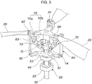
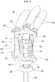
- FIG. 3 and FIG. 4 are views showing a pitching motion of wings.
- FIG. 5 is a view showing a folding or unfolding motion of the wings.
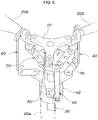
- FIG. 6 is a view showing the propeller apparatus of the air mobility shown in FIG. 1 .
- the propeller apparatus of the air mobility may include a main rotor 10 and a plurality of blades 20 connected to the main rotor 10; a rotation shaft 30 configured to transmit a rotational force of the rotation shaft to the main rotor 10 to rotate the main rotor 10 and the plurality of blades 20; a first movable portion 40 and a second movable portion 50 configured to independently perform vertical motion around the rotation shaft 30; a first link assembly 60 connecting the first movable portion 40 to the plurality of blades 20 so that, during the vertical motion of the first movable portion 40, the plurality of blades 20 is rotated on the spot to perform a pitching motion of the plurality of blades; and a second link assembly 70 connecting the second movable portion 50 to the plurality of blades 20 so that, during the vertical motion of the second movable portion 50, the plurality of blades 20 is rotated and moved to perform a folding or unfolding motion of
- the propeller apparatus of the present invention may be provided to a fuselage or a wing of the air mobility.
- the rotation shaft 30 is connected to a driving motor M, and the plurality of blades 20 are rotated with the rotation shaft 30 and the main rotor 10 by a rotational force transmitted from the driving motor M. Therefore, thrust is generated so that the air mobility may fly.
- components of the present invention may be provided to be inverted vertically.
- the rotation shaft 30 is connected to the driving motor M and is rotated by receiving a rotational force from the driving motor M.
- the main rotor 10 connected to the rotation shaft 30 and the plurality of blades 20 connected to the main rotor 10 are rotated with the rotation shaft 30.
- the first movable portion 40 and the second movable portion 50 that independently perform vertical motion are provided around the rotation shaft 30.
- the first movable portion 40 and the second movable portion 50 are respectively connected to the plurality of blades 20 through the first link assembly 60 and the second link assembly 70.
- the plurality of blades 20 are rotated on the spot by the first link assembly 60 to perform a pitching motion thereof, so that attitude control of the air mobility may be performed.
- the plurality of blades 20 are rotated and moved by the second link assembly 70 to perform a folding or unfolding motion of the plurality of blades, so that the plurality of blades 20 may be folded or unfolded on the air mobility.
- the first movable portion 40 and the second movable portion 50 may be respectively operated by a rotation or linear actuator, and may be moved in the vertical direction while being connected to separate control rods.
- each of the plurality of blades 20 is rotatably connected to the main rotor 10 through a connecting portion 80, and the first link assembly 60 and the second link assembly 70 may be rotatably connected to the connecting portion 80 at different locations.
- the connecting portion 80 is rotatably provided to the main rotor 10, the blade 20 is rotatably connected to the connecting portion 80. Furthermore, the first link assembly 60 and the second link assembly 70 are rotatably connected to the connecting portion 80 at different locations. Accordingly, the blade 20 is provided to the main rotor 10 through the connecting portion 80, and the blade 20 is rotated on the spot by the first link assembly 60 during the vertical motion of the first movable portion 40, or the second link assembly 70 directly rotates the connecting portion 80 so that the plurality of blades 20 are rotated and moved during the vertical motion of the second movable portion 50.
- the connecting portion 80 may be formed in a vertically bent shape so that the first link assembly 60 and the second link assembly 70 are connected to the connecting portion 80 at different locations.
- the blade 20 is connected to a vertical portion 81 of the connecting portion 80 together with the first link assembly 60 to be rotatable about a horizontal shaft of the blade.
- the blade 20 is provided to the main rotor 10 to be rotatable about a vertical shaft of the main rotor 10 through a horizontal portion 82 and the second link assembly 70 is connected to the main rotor 10 to be rotatable about the vertical shaft thereof.
- the plurality of blades 20, the first link assembly 60, and the second link assembly 70 are connected to each other through the connecting portion 80 provided to the main rotor 10, so that attitude and location control of the plurality of blades 20 in a response to the vertical motions of the first movable portion 40 and the second movable portion 50 may be performed.
- the first link assembly 60 for attitude control of the plurality of blades 20 includes: a first connecting link 61 rotatably connected to the first movable portion 40; a second connecting link 62 coupled to the blade 20 and rotatably connected to the connecting portion 80; and a third connecting link 63 rotatably connected to the first connecting link 61 and the second connecting link 62.
- the first link assembly 60 is configured such that the first connecting link 61, the second connecting link 62, and the third connecting link 63 are rotatably connected to each other, whereby, as the blade 20 is rotated on the spot at the connecting portion 80 during vertical motion of the first movable portion 40, a pitching motion of the blade is performed.
- the first connecting link 61 may be provided to the first movable portion 40 to be rotatable about a vertical shaft thereof.
- the second connecting link 62 may be connected to the connecting portion 80 to be rotatable about a horizontal shaft thereof.
- the third connecting link 63 may be connected to the first connecting link 61 and the second connecting link 62 to be rotatable about a horizontal shaft thereof.
- connection of each of the links may be rotatable by a hinge structure.
- a vertical location of the first movable portion 40 is determined by attitude control of the blade 20, and may be controlled by a separate controller.
- the propeller apparatus of the present invention may control pitch of the blade 20 by vertical motion of the first movable portion 40.
- the second link assembly 70 provided for rotating location control of the plurality of blades 20 includes: a fixed link 71 provided on the rotation shaft 30; a first rotating link 72 rotatably connected to the connecting portion 80; a second rotating link 73 rotatably connected to the second movable portion 50 and the first rotating link 72; and a third rotating link 74 rotatably connected to the fixed link 71 and the second rotating link 73.
- the second link assembly 70 is configured such that the fixed link 71, the first rotating link 72, the second rotating link 73, and the third rotating link 74 are rotatably connected to each other.
- the connecting portion 80 is rotated around the main rotor 10, and thus the blade 20 is rotated and moved together with the connecting portion 80 to perform folding of unfolding motion thereof.
- the fixed link 71, the second rotating link 73, and the third rotating link 74 are coupled to each other to be rotatable about horizontal shafts thereof, and the first rotating link 72 is connected to the connecting portion 80 to be rotatable about a vertical shaft thereof, and the second rotating link 73 is connected to the connecting portion 80 to be rotatable about the horizontal shaft thereof.
- the first rotating link 72 may include: a first additional link 72a connected to the connecting portion 80 to be rotatable about a vertical shaft thereof; and a second additional link 72b connected at a first end portion thereof to the first additional link 72a to be rotatable about a vertical shaft thereof and connected at a second end portion thereof to the second rotating link 73 to be rotatable about a horizontal shaft thereof.
- the first additional link 72a may be formed to extend by a predetermined length, and the second additional link 72b may be formed to be bent perpendicularly.
- the second additional link 72b of the first rotating link 72 is moved in conjunction with the second rotating link 73 to be moved in a direction away from or close to the rotation shaft 30.
- the first additional link 72a may be rotated due to movement of the second additional link 72b while being connected to the connecting portion 80, and the connecting portion 80 may be rotated due to rotation of the first additional link 72a, so that rotating location of the blade 20 may be changed.
- the fixed link 71 may be located above the second movable portion 50, and the second movable portion 50 may be moved vertically at a location below the fixed link 71.
- the second rotating link 73 may extend longer than the third rotating link 74. Whereby, when the second movable portion 50 is moved vertically, the second rotating link 73 may be operated in a folding or unfolding form while being supported by the third rotating link 74.
- a vertical location of the second movable portion 50 may be determined by the rotating location of the blade 20, and the location thereof may be controlled by a separate controller.
- the second rotating link 73 connected to the second movable portion 50 is supported by the third rotating link 74, so that the second rotating link 73 is rotated clockwise and the third rotating link 74 is rotated counterclockwise.
- the second rotating link 73 performs unfolding motion, and the first rotating link 72 connected to the second rotating link 73 rotates the connecting portion 80 provided on the main rotor 10. Therefore, the blade 20 coupled to the connecting portion 80 may be rotated and moved in an unfolded direction thereof.
- the first movable portion 40 may include an auxiliary rotor 41 formed in the same shape as the main rotor 10, the first link assembly 60 may be connected to the main rotor 10 and the auxiliary rotor 41.
- the first link assembly 60 may be stably provided in the vertical direction with respect to the plurality of blades 20 disposed along a circumference of the main rotor 10.
- the second movable portion 50 includes an upper slider 51 and a lower slider 52 moved vertically together around the rotation shaft 30.
- the upper slider 51 and the lower slider 52 may be spaced from each other at an upper side and a lower side of the first movable portion 40, and the upper slider 51 and the lower slider 52 may be connected to each other through a connecting shaft 53 slidably passing through the first movable portion 40.
- the connecting shaft 53 is installed to slidably pass through the first movable portion 40 and the auxiliary rotor 41.
- the second link assembly 70 may be rotatably connected to the upper slider 51 and the blade 20.
- the second movable portion 50 includes the lower slider 52 moved vertically by a rotary or linear actuator, and the upper slider 51 coupled to the lower slider 52 through the connecting shaft 53 to be moved together with the lower slider 52 and to which the second link assembly 70 is connected. Accordingly, as the second movable portion 50 includes the upper slider 51 and the lower slider 52, interference between the second link assembly 70 and other components may be minimized. Furthermore, as the lower slider 52 and the upper slider 51 may be connected to each other through the connecting shaft 53 passing through the first movable portion 40, a volume of package may be reduced.
- a blade 20a of the plurality of blades 20 may be connected to the first movable portion 40 through the first link assembly 60, and the rest 20b of the plurality of blades 20 may be connected to the first movable portion 40 and the second movable portion 50 through the first link assembly 60 and the second link assembly 70.
- all the plurality of blades 20 are connected to the first movable portion 40 through the first link assembly 60 so that all the plurality of blades 20 may perform a pitching motion.
- the second movable portion 50 is connected to the other blades 20b through the second link assembly 70, so that the other blades 20b are rotated and moved toward the fixed blade 20a, performing a folding or unfolding motion of the plurality of blades.
- one blade 20a of the three blades 20 is connected to the first movable portion 40 through the first link assembly 60, performing only a pitching motion.
- the other blades 20b are connected to the first movable portion 40 and the second movable portion 50 through the first link assembly 60 and the second link assembly 70, performing a folding or unfolding motion in a response to the rotating location change in addition to the pitching motion.
- the propeller apparatus of the air mobility having the structure described above controls the plurality of blades thereof to be unfolded or folded in a response to flight situation of the air mobility. Accordingly, energy efficiency of the air mobility may be improved and flight distance may be increased by efficient use of the plurality of blades in each flight situation. Furthermore, as a pitching motion of the plurality of blades is performed in addition to a folding or unfolding motion of the plurality of blades, flight performance may be improved.
Landscapes
- Engineering & Computer Science (AREA)
- Aviation & Aerospace Engineering (AREA)
- Mechanical Engineering (AREA)
- Toys (AREA)
- Pivots And Pivotal Connections (AREA)
Applications Claiming Priority (1)
| Application Number | Priority Date | Filing Date | Title |
|---|---|---|---|
| KR1020200175428A KR20220085402A (ko) | 2020-12-15 | 2020-12-15 | 에어모빌리티의 프로펠러 장치 |
Publications (2)
| Publication Number | Publication Date |
|---|---|
| EP4015363A1 true EP4015363A1 (de) | 2022-06-22 |
| EP4015363B1 EP4015363B1 (de) | 2024-02-28 |
Family
ID=77666326
Family Applications (1)
| Application Number | Title | Priority Date | Filing Date |
|---|---|---|---|
| EP21195445.8A Active EP4015363B1 (de) | 2020-12-15 | 2021-09-08 | Propellervorrichtung für luftmobilität |
Country Status (5)
| Country | Link |
|---|---|
| US (1) | US11845535B2 (de) |
| EP (1) | EP4015363B1 (de) |
| JP (1) | JP7635101B2 (de) |
| KR (1) | KR20220085402A (de) |
| CN (1) | CN114633878B (de) |
Families Citing this family (2)
| Publication number | Priority date | Publication date | Assignee | Title |
|---|---|---|---|---|
| GB2627513B (en) * | 2023-02-24 | 2026-03-25 | Bae Systems Plc | A swash plate |
| CN118373001B (zh) * | 2024-06-24 | 2024-08-27 | 安徽羲禾航空科技有限公司 | 一种用于无人飞行器的自动折叠螺旋桨 |
Citations (5)
| Publication number | Priority date | Publication date | Assignee | Title |
|---|---|---|---|---|
| US2658576A (en) * | 1951-03-08 | 1953-11-10 | Piasecki Helicopter Corp | Blade pitch control mechanism |
| US3254725A (en) * | 1963-07-17 | 1966-06-07 | Boeing Co | Aircraft propulsion system |
| US20150274290A1 (en) * | 2013-05-22 | 2015-10-01 | Bell Helicopter Textron Inc. | Folding of rotorcraft rotor blades |
| CN207658045U (zh) * | 2017-12-14 | 2018-07-27 | 长安大学 | 适于飞行汽车的可折叠四旋翼飞行器 |
| US20190016441A1 (en) * | 2014-12-02 | 2019-01-17 | Bell Helicopter Textron Inc. | Blade fold mechanism |
Family Cites Families (9)
| Publication number | Priority date | Publication date | Assignee | Title |
|---|---|---|---|---|
| US3404852A (en) * | 1966-08-24 | 1968-10-08 | Bell Aerospace Corp | Trailing rotor convertiplane |
| US5628620A (en) * | 1991-09-30 | 1997-05-13 | Arlton; Paul E. | Main rotor system for helicopters |
| FR2886993B1 (fr) * | 2005-06-13 | 2007-08-03 | Eurocopter France | Systeme de protection, articulation a soufflet et aeronef |
| US10336447B2 (en) * | 2014-12-02 | 2019-07-02 | Bell Helicopter Textron Inc. | Folding proprotor gimbal lock and blade lock mechanism |
| CN207141389U (zh) | 2017-08-15 | 2018-03-27 | 深圳市道通智能航空技术有限公司 | 折叠螺旋桨、动力组件以及无人飞行器 |
| US11008095B2 (en) | 2018-01-10 | 2021-05-18 | Hangzhou Zero Zero Technology Co., Ltd. | Foldable rotor blade assembly and aerial vehicle with a foldable rotor blade assembly |
| US10843795B2 (en) | 2018-06-13 | 2020-11-24 | Wing Aviation Llc | Folding concentrically mounted propeller blades for drag reduction |
| US10933986B2 (en) | 2018-06-22 | 2021-03-02 | Bell Helicopter Textron Inc. | Blade fold method and apparatus for a tilt rotor hub |
| KR102176258B1 (ko) | 2019-02-27 | 2020-11-09 | 박주현 | 날개 폴딩식 유인 드론 |
-
2020
- 2020-12-15 KR KR1020200175428A patent/KR20220085402A/ko active Pending
-
2021
- 2021-08-27 US US17/459,772 patent/US11845535B2/en active Active
- 2021-08-30 JP JP2021140419A patent/JP7635101B2/ja active Active
- 2021-09-08 EP EP21195445.8A patent/EP4015363B1/de active Active
- 2021-09-22 CN CN202111107770.2A patent/CN114633878B/zh active Active
Patent Citations (5)
| Publication number | Priority date | Publication date | Assignee | Title |
|---|---|---|---|---|
| US2658576A (en) * | 1951-03-08 | 1953-11-10 | Piasecki Helicopter Corp | Blade pitch control mechanism |
| US3254725A (en) * | 1963-07-17 | 1966-06-07 | Boeing Co | Aircraft propulsion system |
| US20150274290A1 (en) * | 2013-05-22 | 2015-10-01 | Bell Helicopter Textron Inc. | Folding of rotorcraft rotor blades |
| US20190016441A1 (en) * | 2014-12-02 | 2019-01-17 | Bell Helicopter Textron Inc. | Blade fold mechanism |
| CN207658045U (zh) * | 2017-12-14 | 2018-07-27 | 长安大学 | 适于飞行汽车的可折叠四旋翼飞行器 |
Also Published As
| Publication number | Publication date |
|---|---|
| KR20220085402A (ko) | 2022-06-22 |
| US20220185450A1 (en) | 2022-06-16 |
| US11845535B2 (en) | 2023-12-19 |
| EP4015363B1 (de) | 2024-02-28 |
| CN114633878A (zh) | 2022-06-17 |
| CN114633878B (zh) | 2026-03-24 |
| JP2022094906A (ja) | 2022-06-27 |
| JP7635101B2 (ja) | 2025-02-25 |
Similar Documents
| Publication | Publication Date | Title |
|---|---|---|
| EP3464061B1 (de) | Propellernabenanordnung mit zusammenklappbaren schaufeln für senkrecht startendes und landendes flugzeug | |
| US11661202B2 (en) | Aerodynamically efficient lightweight vertical take-off and landing aircraft with pivoting rotors and box wing design | |
| EP4324740B1 (de) | Aerodynamisch effizientes leichtes senkrechtstart- und -landeflugzeug mit schwenkbaren rotoren und verstaubaren rotorblättern | |
| CN106573677B (zh) | 具有枢转旋翼和收拢旋翼桨叶的气动高效的轻型垂直起飞和着陆飞机 | |
| EP4015363A1 (de) | Propellervorrichtung für luftmobilität | |
| CN105711831B (zh) | 垂直起降的固定翼无人机 | |
| CN114560084A (zh) | 一种仿生扑翼飞行机器人的自主折展变形翼 | |
| US11745854B2 (en) | Folding propeller for air mobility | |
| CN104443377A (zh) | 包括主俯仰操纵杆和次操纵杆的旋翼飞行器旋翼 | |
| US20150037149A1 (en) | Rotorcraft control system for rotorcraft with two or more rotor systems | |
| US11414183B2 (en) | Compound helicopter having a tiltable jet engine | |
| CN114476023A (zh) | 空中行驶车辆的螺旋桨折叠装置 | |
| WO2021050952A1 (en) | Adaptive ducted fan propulsion system | |
| JPS6157494A (ja) | 飛行機の翼構造 | |
| KR101137822B1 (ko) | 비행체 | |
| EP4514681B1 (de) | Luftfahrzeug und verfahren zum übergang zwischen flugmodi für ein luftfahrzeug | |
| CN117184468A (zh) | 飞行器及飞行器的控制方法 | |
| KR102548772B1 (ko) | 윙-로터를 구비한 비행체 | |
| US12428143B2 (en) | Varying a pitch of a tiltrotor | |
| KR20250050256A (ko) | 동축 로터 기반 복합형 드론 | |
| CN116374157A (zh) | 航空驱动装置、飞行器以及运行航空驱动装置的方法 | |
| CN121376257A (zh) | 一种动力总成可倾转的飞行器及其控制方法 |
Legal Events
| Date | Code | Title | Description |
|---|---|---|---|
| PUAI | Public reference made under article 153(3) epc to a published international application that has entered the european phase |
Free format text: ORIGINAL CODE: 0009012 |
|
| STAA | Information on the status of an ep patent application or granted ep patent |
Free format text: STATUS: THE APPLICATION HAS BEEN PUBLISHED |
|
| AK | Designated contracting states |
Kind code of ref document: A1 Designated state(s): AL AT BE BG CH CY CZ DE DK EE ES FI FR GB GR HR HU IE IS IT LI LT LU LV MC MK MT NL NO PL PT RO RS SE SI SK SM TR |
|
| STAA | Information on the status of an ep patent application or granted ep patent |
Free format text: STATUS: REQUEST FOR EXAMINATION WAS MADE |
|
| 17P | Request for examination filed |
Effective date: 20221222 |
|
| RBV | Designated contracting states (corrected) |
Designated state(s): AL AT BE BG CH CY CZ DE DK EE ES FI FR GB GR HR HU IE IS IT LI LT LU LV MC MK MT NL NO PL PT RO RS SE SI SK SM TR |
|
| GRAP | Despatch of communication of intention to grant a patent |
Free format text: ORIGINAL CODE: EPIDOSNIGR1 |
|
| STAA | Information on the status of an ep patent application or granted ep patent |
Free format text: STATUS: GRANT OF PATENT IS INTENDED |
|
| INTG | Intention to grant announced |
Effective date: 20231108 |
|
| GRAS | Grant fee paid |
Free format text: ORIGINAL CODE: EPIDOSNIGR3 |
|
| GRAA | (expected) grant |
Free format text: ORIGINAL CODE: 0009210 |
|
| STAA | Information on the status of an ep patent application or granted ep patent |
Free format text: STATUS: THE PATENT HAS BEEN GRANTED |
|
| AK | Designated contracting states |
Kind code of ref document: B1 Designated state(s): AL AT BE BG CH CY CZ DE DK EE ES FI FR GB GR HR HU IE IS IT LI LT LU LV MC MK MT NL NO PL PT RO RS SE SI SK SM TR |
|
| REG | Reference to a national code |
Ref country code: GB Ref legal event code: FG4D |
|
| REG | Reference to a national code |
Ref country code: CH Ref legal event code: EP |
|
| REG | Reference to a national code |
Ref country code: DE Ref legal event code: R096 Ref document number: 602021009789 Country of ref document: DE |
|
| REG | Reference to a national code |
Ref country code: IE Ref legal event code: FG4D |
|
| REG | Reference to a national code |
Ref country code: LT Ref legal event code: MG9D |
|
| PG25 | Lapsed in a contracting state [announced via postgrant information from national office to epo] |
Ref country code: IS Free format text: LAPSE BECAUSE OF FAILURE TO SUBMIT A TRANSLATION OF THE DESCRIPTION OR TO PAY THE FEE WITHIN THE PRESCRIBED TIME-LIMIT Effective date: 20240628 |
|
| REG | Reference to a national code |
Ref country code: NL Ref legal event code: MP Effective date: 20240228 |
|
| PG25 | Lapsed in a contracting state [announced via postgrant information from national office to epo] |
Ref country code: LT Free format text: LAPSE BECAUSE OF FAILURE TO SUBMIT A TRANSLATION OF THE DESCRIPTION OR TO PAY THE FEE WITHIN THE PRESCRIBED TIME-LIMIT Effective date: 20240228 |
|
| PG25 | Lapsed in a contracting state [announced via postgrant information from national office to epo] |
Ref country code: GR Free format text: LAPSE BECAUSE OF FAILURE TO SUBMIT A TRANSLATION OF THE DESCRIPTION OR TO PAY THE FEE WITHIN THE PRESCRIBED TIME-LIMIT Effective date: 20240529 |
|
| PG25 | Lapsed in a contracting state [announced via postgrant information from national office to epo] |
Ref country code: RS Free format text: LAPSE BECAUSE OF FAILURE TO SUBMIT A TRANSLATION OF THE DESCRIPTION OR TO PAY THE FEE WITHIN THE PRESCRIBED TIME-LIMIT Effective date: 20240528 Ref country code: NL Free format text: LAPSE BECAUSE OF FAILURE TO SUBMIT A TRANSLATION OF THE DESCRIPTION OR TO PAY THE FEE WITHIN THE PRESCRIBED TIME-LIMIT Effective date: 20240228 Ref country code: HR Free format text: LAPSE BECAUSE OF FAILURE TO SUBMIT A TRANSLATION OF THE DESCRIPTION OR TO PAY THE FEE WITHIN THE PRESCRIBED TIME-LIMIT Effective date: 20240228 |
|
| PG25 | Lapsed in a contracting state [announced via postgrant information from national office to epo] |
Ref country code: ES Free format text: LAPSE BECAUSE OF FAILURE TO SUBMIT A TRANSLATION OF THE DESCRIPTION OR TO PAY THE FEE WITHIN THE PRESCRIBED TIME-LIMIT Effective date: 20240228 |
|
| PG25 | Lapsed in a contracting state [announced via postgrant information from national office to epo] |
Ref country code: RS Free format text: LAPSE BECAUSE OF FAILURE TO SUBMIT A TRANSLATION OF THE DESCRIPTION OR TO PAY THE FEE WITHIN THE PRESCRIBED TIME-LIMIT Effective date: 20240528 Ref country code: NO Free format text: LAPSE BECAUSE OF FAILURE TO SUBMIT A TRANSLATION OF THE DESCRIPTION OR TO PAY THE FEE WITHIN THE PRESCRIBED TIME-LIMIT Effective date: 20240528 Ref country code: NL Free format text: LAPSE BECAUSE OF FAILURE TO SUBMIT A TRANSLATION OF THE DESCRIPTION OR TO PAY THE FEE WITHIN THE PRESCRIBED TIME-LIMIT Effective date: 20240228 Ref country code: LT Free format text: LAPSE BECAUSE OF FAILURE TO SUBMIT A TRANSLATION OF THE DESCRIPTION OR TO PAY THE FEE WITHIN THE PRESCRIBED TIME-LIMIT Effective date: 20240228 Ref country code: IS Free format text: LAPSE BECAUSE OF FAILURE TO SUBMIT A TRANSLATION OF THE DESCRIPTION OR TO PAY THE FEE WITHIN THE PRESCRIBED TIME-LIMIT Effective date: 20240628 Ref country code: HR Free format text: LAPSE BECAUSE OF FAILURE TO SUBMIT A TRANSLATION OF THE DESCRIPTION OR TO PAY THE FEE WITHIN THE PRESCRIBED TIME-LIMIT Effective date: 20240228 Ref country code: GR Free format text: LAPSE BECAUSE OF FAILURE TO SUBMIT A TRANSLATION OF THE DESCRIPTION OR TO PAY THE FEE WITHIN THE PRESCRIBED TIME-LIMIT Effective date: 20240529 Ref country code: FI Free format text: LAPSE BECAUSE OF FAILURE TO SUBMIT A TRANSLATION OF THE DESCRIPTION OR TO PAY THE FEE WITHIN THE PRESCRIBED TIME-LIMIT Effective date: 20240228 Ref country code: ES Free format text: LAPSE BECAUSE OF FAILURE TO SUBMIT A TRANSLATION OF THE DESCRIPTION OR TO PAY THE FEE WITHIN THE PRESCRIBED TIME-LIMIT Effective date: 20240228 Ref country code: BG Free format text: LAPSE BECAUSE OF FAILURE TO SUBMIT A TRANSLATION OF THE DESCRIPTION OR TO PAY THE FEE WITHIN THE PRESCRIBED TIME-LIMIT Effective date: 20240228 |
|
| PG25 | Lapsed in a contracting state [announced via postgrant information from national office to epo] |
Ref country code: PL Free format text: LAPSE BECAUSE OF FAILURE TO SUBMIT A TRANSLATION OF THE DESCRIPTION OR TO PAY THE FEE WITHIN THE PRESCRIBED TIME-LIMIT Effective date: 20240228 Ref country code: PT Free format text: LAPSE BECAUSE OF FAILURE TO SUBMIT A TRANSLATION OF THE DESCRIPTION OR TO PAY THE FEE WITHIN THE PRESCRIBED TIME-LIMIT Effective date: 20240628 |
|
| REG | Reference to a national code |
Ref country code: AT Ref legal event code: MK05 Ref document number: 1661033 Country of ref document: AT Kind code of ref document: T Effective date: 20240228 |
|
| PG25 | Lapsed in a contracting state [announced via postgrant information from national office to epo] |
Ref country code: SE Free format text: LAPSE BECAUSE OF FAILURE TO SUBMIT A TRANSLATION OF THE DESCRIPTION OR TO PAY THE FEE WITHIN THE PRESCRIBED TIME-LIMIT Effective date: 20240228 Ref country code: PT Free format text: LAPSE BECAUSE OF FAILURE TO SUBMIT A TRANSLATION OF THE DESCRIPTION OR TO PAY THE FEE WITHIN THE PRESCRIBED TIME-LIMIT Effective date: 20240628 Ref country code: PL Free format text: LAPSE BECAUSE OF FAILURE TO SUBMIT A TRANSLATION OF THE DESCRIPTION OR TO PAY THE FEE WITHIN THE PRESCRIBED TIME-LIMIT Effective date: 20240228 Ref country code: LV Free format text: LAPSE BECAUSE OF FAILURE TO SUBMIT A TRANSLATION OF THE DESCRIPTION OR TO PAY THE FEE WITHIN THE PRESCRIBED TIME-LIMIT Effective date: 20240228 |
|
| PG25 | Lapsed in a contracting state [announced via postgrant information from national office to epo] |
Ref country code: DK Free format text: LAPSE BECAUSE OF FAILURE TO SUBMIT A TRANSLATION OF THE DESCRIPTION OR TO PAY THE FEE WITHIN THE PRESCRIBED TIME-LIMIT Effective date: 20240228 |
|
| PG25 | Lapsed in a contracting state [announced via postgrant information from national office to epo] |
Ref country code: SM Free format text: LAPSE BECAUSE OF FAILURE TO SUBMIT A TRANSLATION OF THE DESCRIPTION OR TO PAY THE FEE WITHIN THE PRESCRIBED TIME-LIMIT Effective date: 20240228 |
|
| PG25 | Lapsed in a contracting state [announced via postgrant information from national office to epo] |
Ref country code: EE Free format text: LAPSE BECAUSE OF FAILURE TO SUBMIT A TRANSLATION OF THE DESCRIPTION OR TO PAY THE FEE WITHIN THE PRESCRIBED TIME-LIMIT Effective date: 20240228 Ref country code: CZ Free format text: LAPSE BECAUSE OF FAILURE TO SUBMIT A TRANSLATION OF THE DESCRIPTION OR TO PAY THE FEE WITHIN THE PRESCRIBED TIME-LIMIT Effective date: 20240228 |
|
| PG25 | Lapsed in a contracting state [announced via postgrant information from national office to epo] |
Ref country code: AT Free format text: LAPSE BECAUSE OF FAILURE TO SUBMIT A TRANSLATION OF THE DESCRIPTION OR TO PAY THE FEE WITHIN THE PRESCRIBED TIME-LIMIT Effective date: 20240228 |
|
| PG25 | Lapsed in a contracting state [announced via postgrant information from national office to epo] |
Ref country code: SK Free format text: LAPSE BECAUSE OF FAILURE TO SUBMIT A TRANSLATION OF THE DESCRIPTION OR TO PAY THE FEE WITHIN THE PRESCRIBED TIME-LIMIT Effective date: 20240228 |
|
| PG25 | Lapsed in a contracting state [announced via postgrant information from national office to epo] |
Ref country code: SM Free format text: LAPSE BECAUSE OF FAILURE TO SUBMIT A TRANSLATION OF THE DESCRIPTION OR TO PAY THE FEE WITHIN THE PRESCRIBED TIME-LIMIT Effective date: 20240228 Ref country code: SK Free format text: LAPSE BECAUSE OF FAILURE TO SUBMIT A TRANSLATION OF THE DESCRIPTION OR TO PAY THE FEE WITHIN THE PRESCRIBED TIME-LIMIT Effective date: 20240228 Ref country code: RO Free format text: LAPSE BECAUSE OF FAILURE TO SUBMIT A TRANSLATION OF THE DESCRIPTION OR TO PAY THE FEE WITHIN THE PRESCRIBED TIME-LIMIT Effective date: 20240228 Ref country code: EE Free format text: LAPSE BECAUSE OF FAILURE TO SUBMIT A TRANSLATION OF THE DESCRIPTION OR TO PAY THE FEE WITHIN THE PRESCRIBED TIME-LIMIT Effective date: 20240228 Ref country code: DK Free format text: LAPSE BECAUSE OF FAILURE TO SUBMIT A TRANSLATION OF THE DESCRIPTION OR TO PAY THE FEE WITHIN THE PRESCRIBED TIME-LIMIT Effective date: 20240228 Ref country code: CZ Free format text: LAPSE BECAUSE OF FAILURE TO SUBMIT A TRANSLATION OF THE DESCRIPTION OR TO PAY THE FEE WITHIN THE PRESCRIBED TIME-LIMIT Effective date: 20240228 Ref country code: AT Free format text: LAPSE BECAUSE OF FAILURE TO SUBMIT A TRANSLATION OF THE DESCRIPTION OR TO PAY THE FEE WITHIN THE PRESCRIBED TIME-LIMIT Effective date: 20240228 |
|
| P01 | Opt-out of the competence of the unified patent court (upc) registered |
Free format text: CASE NUMBER: UPC_APP_120888/2023 Effective date: 20230510 |
|
| REG | Reference to a national code |
Ref country code: DE Ref legal event code: R097 Ref document number: 602021009789 Country of ref document: DE |
|
| PG25 | Lapsed in a contracting state [announced via postgrant information from national office to epo] |
Ref country code: IT Free format text: LAPSE BECAUSE OF FAILURE TO SUBMIT A TRANSLATION OF THE DESCRIPTION OR TO PAY THE FEE WITHIN THE PRESCRIBED TIME-LIMIT Effective date: 20240228 |
|
| PG25 | Lapsed in a contracting state [announced via postgrant information from national office to epo] |
Ref country code: IT Free format text: LAPSE BECAUSE OF FAILURE TO SUBMIT A TRANSLATION OF THE DESCRIPTION OR TO PAY THE FEE WITHIN THE PRESCRIBED TIME-LIMIT Effective date: 20240228 |
|
| PLBE | No opposition filed within time limit |
Free format text: ORIGINAL CODE: 0009261 |
|
| STAA | Information on the status of an ep patent application or granted ep patent |
Free format text: STATUS: NO OPPOSITION FILED WITHIN TIME LIMIT |
|
| 26N | No opposition filed |
Effective date: 20241129 |
|
| PG25 | Lapsed in a contracting state [announced via postgrant information from national office to epo] |
Ref country code: SI Free format text: LAPSE BECAUSE OF FAILURE TO SUBMIT A TRANSLATION OF THE DESCRIPTION OR TO PAY THE FEE WITHIN THE PRESCRIBED TIME-LIMIT Effective date: 20240228 Ref country code: MC Free format text: LAPSE BECAUSE OF FAILURE TO SUBMIT A TRANSLATION OF THE DESCRIPTION OR TO PAY THE FEE WITHIN THE PRESCRIBED TIME-LIMIT Effective date: 20240228 |
|
| REG | Reference to a national code |
Ref country code: CH Ref legal event code: PL |
|
| PG25 | Lapsed in a contracting state [announced via postgrant information from national office to epo] |
Ref country code: LU Free format text: LAPSE BECAUSE OF NON-PAYMENT OF DUE FEES Effective date: 20240908 |
|
| REG | Reference to a national code |
Ref country code: BE Ref legal event code: MM Effective date: 20240930 |
|
| PG25 | Lapsed in a contracting state [announced via postgrant information from national office to epo] |
Ref country code: BE Free format text: LAPSE BECAUSE OF NON-PAYMENT OF DUE FEES Effective date: 20240930 |
|
| PG25 | Lapsed in a contracting state [announced via postgrant information from national office to epo] |
Ref country code: CH Free format text: LAPSE BECAUSE OF NON-PAYMENT OF DUE FEES Effective date: 20240930 |
|
| PG25 | Lapsed in a contracting state [announced via postgrant information from national office to epo] |
Ref country code: IE Free format text: LAPSE BECAUSE OF NON-PAYMENT OF DUE FEES Effective date: 20240908 |
|
| PGFP | Annual fee paid to national office [announced via postgrant information from national office to epo] |
Ref country code: DE Payment date: 20250820 Year of fee payment: 5 |
|
| PGFP | Annual fee paid to national office [announced via postgrant information from national office to epo] |
Ref country code: GB Payment date: 20250820 Year of fee payment: 5 |
|
| PGFP | Annual fee paid to national office [announced via postgrant information from national office to epo] |
Ref country code: FR Payment date: 20250821 Year of fee payment: 5 |
|
| PG25 | Lapsed in a contracting state [announced via postgrant information from national office to epo] |
Ref country code: CY Free format text: LAPSE BECAUSE OF FAILURE TO SUBMIT A TRANSLATION OF THE DESCRIPTION OR TO PAY THE FEE WITHIN THE PRESCRIBED TIME-LIMIT; INVALID AB INITIO Effective date: 20210908 |
|
| PG25 | Lapsed in a contracting state [announced via postgrant information from national office to epo] |
Ref country code: HU Free format text: LAPSE BECAUSE OF FAILURE TO SUBMIT A TRANSLATION OF THE DESCRIPTION OR TO PAY THE FEE WITHIN THE PRESCRIBED TIME-LIMIT; INVALID AB INITIO Effective date: 20210908 |