EP4015364B1 - Dispositif de blocage de l'angle de pas - Google Patents
Dispositif de blocage de l'angle de pas Download PDFInfo
- Publication number
- EP4015364B1 EP4015364B1 EP20400027.7A EP20400027A EP4015364B1 EP 4015364 B1 EP4015364 B1 EP 4015364B1 EP 20400027 A EP20400027 A EP 20400027A EP 4015364 B1 EP4015364 B1 EP 4015364B1
- Authority
- EP
- European Patent Office
- Prior art keywords
- rotor
- pitch angle
- blade
- attachment means
- extension
- Prior art date
- Legal status (The legal status is an assumption and is not a legal conclusion. Google has not performed a legal analysis and makes no representation as to the accuracy of the status listed.)
- Active
Links
Images


Classifications
-
- B—PERFORMING OPERATIONS; TRANSPORTING
- B64—AIRCRAFT; AVIATION; COSMONAUTICS
- B64C—AEROPLANES; HELICOPTERS
- B64C27/00—Rotorcraft; Rotors peculiar thereto
- B64C27/32—Rotors
- B64C27/322—Blade travel limiting devices, e.g. droop stops
-
- B—PERFORMING OPERATIONS; TRANSPORTING
- B64—AIRCRAFT; AVIATION; COSMONAUTICS
- B64C—AEROPLANES; HELICOPTERS
- B64C27/00—Rotorcraft; Rotors peculiar thereto
- B64C27/32—Rotors
- B64C27/46—Blades
- B64C27/473—Constructional features
- B64C27/50—Blades foldable to facilitate stowage of aircraft
-
- B—PERFORMING OPERATIONS; TRANSPORTING
- B64—AIRCRAFT; AVIATION; COSMONAUTICS
- B64C—AEROPLANES; HELICOPTERS
- B64C11/00—Propellers, e.g. of ducted type; Features common to propellers and rotors for rotorcraft
- B64C11/30—Blade pitch-changing mechanisms
- B64C11/32—Blade pitch-changing mechanisms mechanical
-
- B—PERFORMING OPERATIONS; TRANSPORTING
- B64—AIRCRAFT; AVIATION; COSMONAUTICS
- B64C—AEROPLANES; HELICOPTERS
- B64C27/00—Rotorcraft; Rotors peculiar thereto
- B64C27/04—Helicopters
- B64C27/06—Helicopters with single rotor
Definitions
- the present embodiments relate to a pitch angle blocking device and, more particularly, to a pitch angle blocking device for blocking the pitch angle of a multi-blade rotor of a rotary-wing aircraft in non-operational mode of the rotary-wing aircraft.
- the present embodiments also relate to a multi-blade rotor of a rotary-wing aircraft that is adapted to receiving such a pitch angle blocking device and to a rotary-wing aircraft with such a multi-blade rotor.
- Rotors are usually provided for producing thrust in a predetermined direction during operation.
- the thrust produced by the rotor blades of a rotor can be controlled in two different ways: either by controlling the rotation speed of the rotor blades around the rotor axis, or by controlling an aerodynamic lift coefficient of the rotor blades.
- the aerodynamic lift coefficient is usually controlled by adjusting an underlying pitch angle of the rotor blades.
- Pitch angle adjustment is also desirable to compensate for asymmetries in air velocity, for example during operation in non-axial inflow fields i.e., when the air flow has a component that is perpendicular to the rotor plane and at the same time a component that is lateral to the rotor plane.
- some rotor blades are rotating against the lateral air flow while others are rotating with the lateral air flow, which leads to unbalanced lift at the different rotor blades, depending on their current position. Unbalanced lift often leads to vibratory stresses on the rotor blades. Controlling the pitch angle of each rotor blade separately according to its rotation position, which is sometimes also referred to as "cyclic pitch control" or "cyclic pitch actuation”, may lead to an evenly distributed lift on all rotor blades.
- Controlling the pitch angle of rotor blades usually requires the control of flexible joints in rotor assemblies.
- each associated rotor blade is articulated and controlled individually over its azimuth angle of rotation, which often requires complex, heavy, and cost intensive pitch adjustment devices.
- pitch adjustment devices generally include hydraulic actuators that require active control means with external energy supplies to adjust the pitch angle of each rotor blade individually.
- Actively controlled rotor assemblies are usually not only provided with cyclic, but also with collective pitch adjustment devices in order to be effective regarding lift and drag.
- the cyclic and collective pitch adjustment devices comprise pitch control rods that are moved by a swashplate, or by an axially moveable ring around a respective rotor mast. These elements need to be moved by additional actuators.
- the pitch angles of the rotor blades often change only a short period of time after the engine that drives the rotor and the associated pitch adjustment devices have been turned off, and the associated rotary-wing aircraft enters a non-operational mode.
- a rotary-wing aircraft that remains in the non-operational mode for a longer period of time is often stowed in a hangar or in a hangar deck of a ship such as a helicopter carrier or an aircraft carrier.
- the rotor blades are often folded.
- the rotor blades When the rotor blades are folded, they stand nearly perpendicular to their pitch rotation axis, and gravity force, aerodynamic forces caused by wind, and/or other forces (e.g., the acceleration of the ship on which the rotary-wing aircraft is located) would cause a torque moment on the rotor blade root.
- the torque moment could cause serious damage on the rotor blade attachment and/or the pitch adjustment devices including the hydraulic actuators, the pitch control rods, and the swashplate. Therefore, the pitch rotation of the rotor blades has to be fixed to prevent the rotor blades from performing an undesired downward movement.
- document EP 1 996 454 A1 describes a rotor assembly having a rotor hub, a plurality of yokes, and a plurality of swing arms.
- Each swing arm is movably positioned on the rotor hub for rotation between an unlocked position and a locked position.
- the yokes are freely movable about a pitch axis and a lead/lag axis when the swing arms are in the unlocked position and the yokes are locked in a predetermined pitch position and a predetermined lead/lag position when the swing arms are in the locked position.
- Document US 5,951,251 A describes a locking device that comprises for each blade at least one first subassembly with a fork for locking a finger, one of the fork and finger pivoting on a chassis attached laterally to the hub between the linking members of two neighboring blades, the other element being fixed to the linking member and projecting laterally towards the other linking member so that the pivoting element can be moved between a position in which it is engaged over the finger for locking the blade at least in terms of pitch, and a disengaged position for unlocking.
- PASR pitch actuation system restraint
- the PASR device includes permanent adapter brackets that are permanently mounted in combination with the rotor hub arms and temporary adapter bracket and quick release pins for each main rotor blade to be folded.
- a temporary adapter bracket Prior to implementing blade folding operations, a temporary adapter bracket is secured in combination with the pitch control horn of each main rotor blade and the permanent adapter bracket of the adjacent rotor hub arm by means of the quick release pins.
- Each temporary adapter bracket and permanent adapter bracket functions as a rigid structural interconnection that effectively locks the pitch control horn in position during blade folding operations such that displacements induced in the main rotor blade during blade folding operations cannot be coupled into the pitch actuation system.
- lock units that are removably appended between the rotor assembly and each blade pitch housing attached to a helicopter blade and that are usable to restrict upward rotation of the helicopter blades.
- a base portion of a lock unit may be configured to be held in position by a removable pin device.
- An extendible device extending from the base portion to a surface of a blade pitch housing can be adjusted to press the base portion back against a surface of the rotor assembly.
- the lock unit thereby restricts these surfaces of the blade pitch housing and rotor assembly from moving closer to each other and thereby restricts upward rotation of the blade pitch housing and its attached helicopter blade.
- the lock units are readily removable in preparation for returning a helicopter to active use.
- an objective is to provide a pitch angle blocking device for blocking the pitch angle of a multi-blade rotor of a rotary-wing aircraft in non-operational mode of the rotary-wing aircraft.
- the pitch angle blocking device should prevent damage to the rotor blade attachments, and, in particular, damage to hydraulic actuators, control rods, and/or the swashplate of the rotor blade pitch control system in non-operational mode of the rotary-wing aircraft.
- the pitch angle blocking device should be easily installable and removable without adding weight to the rotary-wing aircraft in operational mode.
- the pitch angle blocking device should also allow for performing advantageous blade folding procedures.
- a pitch angle blocking device for blocking the pitch angle of a multi-blade rotor of a rotary-wing aircraft in non-operational mode of the rotary-wing aircraft, the multi-blade rotor having neighboring first and second rotor blades in circumferential direction that extend from a rotor hub, comprises first attachment means configured to be non-rotatably and releasably attached to the first rotor blade spaced apart from the rotor hub; second attachment means configured to be non-rotatably and releasably attached to a second rotor blade spaced apart from the rotor hub; and a connecting device that non-rotatably connects the first attachment means with the second attachment means.
- the principle of the pitch angle blocking device is to apply a bracket to a rotor blade or to the control cuff of a rotor blade assembly and connecting this bracket to another rotor blade or to the control cuff of another rotor blade assembly.
- two brackets can be attached to two adjacent rotor blades or to two control cuffs of two adjacent rotor blades, and these two brackets can be connected to each other.
- a rotary-wing aircraft's main rotor e.g., the main rotor of a helicopter
- main rotor e.g., the main rotor of a helicopter
- tail rotor or propeller with adjustable pitch only has one degree of freedom.
- a pair of brackets between two rotor blades can constrain (i.e., block or fix) one or two of the degrees of freedom of the rotor based on the particular implementation of the pair of brackets.
- the pair of brackets can be attached to the rotor blade or the control cuff of the rotor blade by means that can transfer torsion loads of the rotor blade or rotor blade control cuff.
- This torsion transferring connection may include two or more fasteners such as pins, bolts, or clamps.
- the two or more fasteners may be attached to holes, slots, rails, and/or dovetails or similar devices on the rotor blades or control cuffs of the rotor blades.
- the two or more fasteners may form a cuff that fits the outer shape of the rotor blade or the control cuff of the rotor blade.
- selecting a non-circular cross section for the cuff may enable the transfer of torque from the rotor blade or control cuff of the rotor blade via the cuff with non-circular cross section.
- Fixing or blocking the pitch angles of the rotor blades may enable advantageous blade folding procedures.
- the above-described pitch angle blocking device can be applied externally to the rotor blades or control cuffs of the rotor blades with minimum flying on board equipment, which reduces the weight of the rotary-wing aircraft in operational mode compared to prior art solutions.
- the above-described pitch angle blocking device keeps the rotor control system out of the load path for rotor blade fixation. Moreover, the above-described pitch angle blocking device can be applied externally while the hydraulic system of the pitch adjustment device is active, without the risks involved with installing fixation devices in the powered rotor control system.
- the first attachment means further comprises at least one of a strut, and a fastener that is configured to non-rotatably and releasably attach the strut to the first rotor blade; a bracket that at least partially encompasses the first rotor blade, and at least two fasteners that are configured to non-rotatably and releasably attach the bracket to the first rotor blade; or a non-circular clamp with first and second clamping arms and a fastener that is configured to non-rotatably and releasably attach the first and second clamping arms of the non-circular clamp with each other such that the non-circular clamp encompasses the first rotor blade.
- the second attachment means further comprises at least one of an additional strut, and an additional fastener that is configured to non-rotatably and releasably attach the additional strut to the second rotor blade; an additional bracket that at least partially encompasses the second rotor blade, and at least two additional fasteners that are configured to non-rotatably and releasably attach the additional bracket to the second rotor blade; or an additional non-circular clamp with first and second clamping arms and an additional fastener that is configured to non-rotatably and releasably attach the first and second clamping arms of the additional non-circular clamp with each other such that the additional non-circular clamp encompasses the second rotor blade.
- the fastener and the additional fastener comprise at least one of a threaded rod, a nut, a bolt, a pin, a quick release pin, a bearing, a spherical washer, or an elastic element.
- the at least one of the strut, the bracket, or the non-circular clamp, the at least one of the additional strut, the additional bracket, or the additional non-circular clamp, and the connecting device are integrally formed.
- the connecting device further comprises a first extension that extends from the first attachment means; and a second extension that extends from the second attachment means.
- the connecting device further comprises at least one interface connection that connects the first extension with at least one of the second attachment means or the second extension.
- the at least one interface connection further comprises a length adjustment device that couples the first extension with the at least one of the second attachment means or the second extension and that is configured to adjust a distance between the first extension and the at least one of the second attachment means or the second extension.
- the at least one interface connection further comprises at least one interface fastener that couples the first extension with the at least one of the second attachment means or the second extension.
- the at least one interface fastener comprises at least one of a screw, a nut and a bolt, a threaded rod, or a rivet.
- the at least one interface connection further comprises a slot in the first extension through which the at least one interface fastener is adapted to slide for enabling a displacement of the first extension relative to the at least one of the second attachment means or the second extension.
- a multi-blade rotor of a rotary-wing aircraft comprises:
- the first receiving means comprise at least one of a threaded rod, a bearing, an elastic element, a threaded hole, or a non-threaded hole.
- the second receiving means comprise a non-circular cross section of the second rotor blade at the second location.
- a rotary-wing aircraft comprises the multi-blade rotor described above.
- FIG 1 is a diagram of an illustrative rotary-wing aircraft 100 having at least one rotor 110 with a rotor shaft 115.
- the rotary-wing aircraft 100 which is sometimes also referred to as rotorcraft 100, is exemplarily illustrated as a helicopter.
- helicopter the rotorcraft 100 is hereinafter referred to as the "helicopter" 100.
- helicopter 100 has a fuselage 120 that forms an airframe of the helicopter 100.
- the fuselage 120 is connected to a suitable landing gear and exemplarily forms a cabin 123 and a rear fuselage 127.
- the rear fuselage 127 is connected to a tail boom 130.
- helicopter 100 may include at least one counter-torque device 140 configured to provide counter-torque during operation, i.e. to counter the torque created by rotation of the at least one rotor 110 for purposes of balancing the helicopter 100 in terms of yaw. If desired, counter-torque device 140 may be shrouded.
- the at least one counter-torque device 140 is illustratively provided at an aft section of the tail boom 130 and may have a tail rotor 145.
- the aft section of the tail boom 130 may include a fin 150.
- the tail boom 130 may be provided with a suitable horizontal stabilizer 135.
- the at least one rotor 110 is a multi-blade rotor 110, for providing lift and forward or backward thrust during operation.
- the at least one multi-blade rotor 110 comprises a plurality of rotor blades 112 that are mounted at an associated rotor head 114 with a rotor hub 113 to a rotor shaft 115, which rotates in operation of the helicopter 100 around an associated rotor axis 117 in a rotor plane 119.
- each rotor blade 112 may be connected with the rotor shaft 115 via flexible joints or control cuffs.
- each rotor blade 112 may be articulated and controlled individually over its azimuth angle of rotation using pitch adjustment devices that adjust the pitch angle of each rotor blade 112 individually.
- the multi-blade rotor 110 may include cyclic and collective pitch adjustment devices such as pitch control rods, a swashplate, hydraulic actuators, etc. Multi-blade rotor 110 may have three degrees of freedom for the pitch angles of all rotor blades 112, while the tail rotor 145 with adjustable pitch only has one degree of freedom.
- the rotor blades 112 may cause serious damage to the pitch adjustment devices.
- the rotor blades 112 of the multi-blade rotor 110 are often folded to allow for a denser stowage.
- a pitch angle blocking device may be mounted to the multi-blade rotor 110 to fix or block the pitch angle of the rotor blades 112 in non-operational mode of the rotary-wing aircraft 100.
- a rotor blade 112 is considered to include everything between a rotor hub 113 and a rotor tip.
- the rotor blade 112 is considered to include not only the blade itself, but also any control cuff, flexbeam or similar devices onto which a pitch angle blocking device as described below may be mounted.
- Figure 2 is a three-dimensional diagram of an illustrative multi-blade rotor 110 of a rotary-wing aircraft (e.g., helicopter 100 of Figure 1 ) with a pitch angle blocking device 200 for blocking the pitch angle of the multi-blade rotor 110 in non-operational mode of the rotary-wing aircraft in accordance with some embodiments.
- a pitch angle blocking device 200 for blocking the pitch angle of the multi-blade rotor 110 in non-operational mode of the rotary-wing aircraft in accordance with some embodiments.
- the multi-blade rotor 110 may have five rotor blades 112 that extend from rotor hub 113. If desired, the multi-blade rotor 110 may have more or less than five rotor blades 115. For example, the multi-blade rotor 110 may have three, four, six, seven, or more rotor blades 112.
- Pitch angle blocking device 200 is installed on neighboring first and second rotor blades 112 in circumferential direction 205 of the multi-blade rotor 110 to block the pitch angle of the multi-blade rotor 110.
- Pitch angle blocking device 200 comprises first attachment means 210, second attachment means 210, and a connecting device 230 that non-rotatably connects the first attachment means with the second attachment means 210.
- the first attachment means 210 is configured to be non-rotatably and releasably attached to the first rotor blade 112 spaced apart from the rotor hub 113.
- first attachment means 210 may be attached to first rotor blade 112 at location 520.
- the first attachment means 210 is configured to be non-rotatably and releasably attached to the first rotor blade 112 at location 520, which is located at a predetermined distance from the rotor hub 113.
- the first attachment means 210 may include at least one of a strut and a fastener that is configured to non-rotatably and releasably attach the strut to the first rotor blade 112, a bracket 250 that at least partially encompasses the first rotor blade 112, and at least two fasteners 255 that are configured to non-rotatably and releasably attach the bracket 250 to the first rotor blade 112, or a non-circular clamp with first and second clamping arms and a fastener that is configured to non-rotatably and releasably attach the first and second clamping arms of the non-circular clamp with each other such that the non-circular clamp encompasses the first rotor blade 112.
- the first attachment means 210 includes a bracket 250 that encompasses at least half of the first rotor blade 112.
- Two fasteners 255 non-rotatably and releasably attach the bracket 250 to the first rotor blade 112.
- the two fasteners 255 may attach the bracket 250 to the first rotor blade 112 on opposing sides of the first rotor blade 112.
- one fastener 255 may attach the bracket 250 to an upper portion of the first rotor blade 112, and another fastener 255 may attach the bracket 250 to a lower portion of the first rotor blade 112.
- the second attachment means 210 is configured to be non-rotatably and releasably attached to the second rotor blade 112 spaced apart from the rotor hub 113.
- second attachment means 210 may be attached to second rotor blade 112 at location 520.
- the second attachment means 210 is configured to be non-rotatably and releasably attached to the second rotor blade 112 at location 520, which is located at a predetermined distance from the rotor hub 113.
- the second attachment means 210 may include at least one of an additional strut, and an additional fastener that is configured to non-rotatably and releasably attach the additional strut to the second rotor blade 112, an additional bracket 250 that at least partially encompasses the second rotor blade 112, and at least two additional fasteners 255 that are configured to non-rotatably and releasably attach the additional bracket 250 to the second rotor blade 112, or an additional non-circular clamp with first and second clamping arms and an additional fastener that is configured to non-rotatably and releasably attach the first and second clamping arms of the additional non-circular clamp with each other such that the additional non-circular clamp encompasses the second rotor blade 112.
- the second attachment means 210 includes an additional bracket 250 that encompasses at least half of the second rotor blade 112.
- Two additional fasteners 255 non-rotatably and releasably attach the additional bracket 250 to the second rotor blade 112.
- the two additional fasteners 255 may attach the additional bracket 250 to the second rotor blade 112 on opposing sides of the second rotor blade 112.
- one of the two additional fasteners 255 may attach the bracket 250 to an upper portion of the second rotor blade 112, and another one of the two additional fasteners 255 may attach the bracket 250 to a lower portion of the second rotor blade 112.
- the fastener 255 and the additional fastener 255 may include at least one of a threaded rod, a nut, a bolt, a pin, a quick release pin, a bearing, a spherical washer, or an elastic element.
- the first rotor blade 112 may have two threaded holes, and the two fasteners 255 may be bolts that, together with the threaded holes, fasten the bracket 250 to the first rotor blade 112.
- the first rotor blade 112 may have two holes, and the two fasteners may be quick release pins that, together with the two holes, fasten the bracket 250 to the first rotor blade 112.
- the connecting device 230 that non-rotatably connects the first attachment means 210 with the second attachment means 210 may include a first extension 220 that extends from the first attachment means 210, and a second extension 220 that extends from the second attachment means 210.
- first attachment means 210 and the first extension 220 are integrally formed
- second attachment means 210 and the second extension 220 are integrally formed.
- the connecting device 230 may include at least one interface connection 240 that connects the first extension 220 with at least one of the second attachment means 210 or the second extension 220.
- the at least one interface connection 240 may include at least one interface fastener 245 that couples the first extension 220 with the at least one of the second attachment means 210 or the second extension 220.
- the at least one interface fastener 245 may include at least one of a screw, a nut and a bolt, a threaded rod, or a rivet.
- the connecting device 230 includes two interface connections 240, each having one interface fastener 245 that couples the first and second extensions 220 with each other.
- the two interface fasteners 245 may include two long threaded rods and nuts.
- the threaded rods may be connected via bearings or spherical washers to one of the two extensions 220.
- a nut and a second bearing or second set of spherical washers may be threaded onto the other end of the threaded rods at the other one of the two extensions 220, thereby fastening the two extensions with each other at the two interface connections 240.
- the threaded rods may have a predetermined length.
- the predetermined length may be selected to allow the clamping length to be shortened from a long clamping length during initial installment of the pitch angle blocking device 200 to a shorter clamping length during the fixation period. Thereby, certain pitch angles may be set on each one of the rotor blades 112.
- the interface fasteners 245 may be disassembled first. Thus, using long threaded rods may allow to slowly releasing any potential energy stored in the system.
- FIG 3 is a diagram of the illustrative multi-blade rotor 110 of Figure 2 .
- the multi-blade rotor 110 is adapted to receiving a pitch angle blocking device 200 for blocking the pitch angle of the multi-blade rotor 110 in non-operational mode of the associated rotary-wing aircraft.
- the multi-blade rotor 110 includes a rotor hub 113 and neighboring first and second rotor blades 112 in circumferential direction 205 that extend from the rotor hub 113.
- An illustrative pitch angle blocking device 200 which is seen from above the rotary-wing aircraft in a direction parallel to the rotor shaft (e.g., rotor shaft 115 of helicopter 100 of Figure 1 ), may be installed on the neighboring first and second rotor blades 112 to block the pitch angle of the illustrative multi-blade rotor 110.
- the first rotor blade 112 comprises first receiving means at a first location 520 that is spaced apart from the rotor hub 113 and configured to receiving at least a portion of a first attachment means 210 of the pitch angle blocking device 200.
- the second rotor blade 112 comprises second receiving means at a second location 520 that is spaced apart from the rotor hub 113 and configured to receiving at least a portion of the second attachment means 210 of the pitch angle blocking device 200.
- a connecting device 230 non-rotatably connects the first attachment means 210 with the second attachment means 210.
- Cross sectional diagrams along cut line A-A of illustrative pitch angle devices 200 for blocking the pitch angle of a multi-blade rotor 110 of a rotary-wing aircraft in non-operational mode of the rotary-wing aircraft are shown in Figures 4 to 17 .
- Figure 4 is a diagram of a cross section of an illustrative pitch angle blocking device 200 with two brackets 250, two extensions 220, and two interface connections 240.
- respective first and second brackets 250 of the two brackets 250 and respective first and second extensions 220 of the two extensions may be integrally formed.
- the two brackets 210 are configured to be non-rotatably and releasably attached to two neighboring rotor blades 112 of a multi-blade rotor (e.g., multi-blade rotor 110 of Figure 1 to Figure 3 ). Each one of the two brackets 250 may at least partially encompass one of the two neighboring rotor blades 112.
- At least two fasteners 255 may be configured to non-rotatably and releasably attach each one of the two brackets 250 to a respective one of the two neighboring rotor blades 112.
- two fasteners 255 may attach one of the two brackets 250 to the first rotor blade 112, and two other fasteners 255 may attach the other one of the two brackets 250 to the second rotor blade 112.
- the at least two fasteners 255 may include at least one of a threaded rod, a nut, a bolt, a pin, a quick release pin, a bearing, a spherical washer, or an elastic element.
- each one of the two neighboring rotor blades 112 may include two receiving means 510 for receiving the at least two fasteners 255.
- the first rotor blade 112 may include two first receiving means 510
- the second rotor blade 112 may include two second receiving means 510.
- the receiving means 510 may include at least one of a threaded rod, a bearing, an elastic element, a threaded hole, or a non-threaded hole.
- the four receiving means 510 may all be implemented as a threaded or a non-threaded hole, and the corresponding fasteners 255 may be implemented as quick release pins.
- the four receiving means 510 may be selected to be of the same type, and the four fasteners 255 may be selected to be of the same type. However, at least one receiving means 510 and the associated fastener 255 may be selected to be of a different type than the other receiving means 510 and fasteners 255.
- one of the receiving means 510 may be a threaded rod and the corresponding fastener 255 a nut, while the other receiving means are implemented as holes and the corresponding fasteners as quick release pins.
- the connecting device 230 may include two interface connections 240.
- each one of the two interface connections 240 may include at least one interface fastener 245 that couples the two extensions 220 with the respective counterpart attachment means.
- a first interface fastener 245 may couple the first extension 220 of the first bracket 250 to the second bracket 250
- a second interface fastener 245 may couple the second extension 220 of the second bracket 250 to the first bracket 250.
- the two interface connections 240 may include at least one of a screw, a nut and bolt, a threaded rod, or a rivet.
- each one of the two interface connections 240 includes as interface fastener 245 a threaded rod and a nut.
- the threaded rod is connected to the associated bracket 250 via a bearing or a spherical washer.
- the threaded rod passes through a hole in the respectively adjacent extension 220, and a nut is threaded onto the threaded rod to fasten the extension 220 with bracket 250.
- Figure 5 is a diagram of a cross section of an illustrative pitch angle blocking device 200 with a connecting device 230 that non-rotatably connects first and second attachment means 210 in accordance with some embodiments.
- the first attachment means 210 may include a bracket 250 that at least partially encompasses the first rotor blade 112.
- the second attachment means 210 may include a strut 310.
- the bracket 250, the strut 310, and the connecting device 230 are integrally formed.
- the first attachment means 210 may further include at least two fasteners 255 that are configured to non-rotatably and releasably attach the bracket 250 to the first rotor blade 112.
- the second attachment means 210 may further include an additional fastener 255 that is configured to non-rotatably and releasably attach the strut 310 to the second rotor blade 112.
- the at least two fasteners 255 and/or the additional fastener 255 may include at least one of a threaded rod, a nut, a bolt, a pin, a quick release pin, a bearing, a spherical washer, or an elastic element.
- the first rotor blade 112 may include two receiving means 510 for receiving the at least two fasteners 255.
- the second rotor blade 112 may include only one receiving means 510.
- Each one of the receiving means 510 may include at least one of a threaded rod, a bearing, an elastic element, a threaded hole, or a non-threaded hole.
- the additional fastener 255 and the associated receiving means 510 may be selected to include an elastic element, a bearing, or spherical washers such that the second rotor blade 112 can transfer torsion moments to the pitch angle blocking device 200.
- the additional fastener 255 may be selected to be a threaded rod.
- the pitch angle blocking device 200 may be able to constrain a single degree of freedom of the multi-blade rotor.
- Figure 6 is a diagram of a cross section of an illustrative pitch angle blocking device 200 with a connecting device 230 that non-rotatably connects first and second attachment means 210 in accordance with some embodiments.
- the first attachment means 210 may include a bracket 250 that at least partially encompasses the first rotor blade 112 and at least two fasteners 255 that are configured to non-rotatably and releasably attach the bracket 250 to the first rotor blade 112.
- the second attachment means 210 may include an additional bracket 250 that at least partially encompasses the second rotor blade 112, and at least two additional fasteners 255 that are configured to non-rotatably and releasably attach the additional bracket 250 to the second rotor blade 112.
- the connecting device 230 includes a first extension 220 that extends from the first attachment means 210 and a second extension 220 that extends from the second attachment means 210. As shown in Figure 6 , the connecting device 230 further includes an interface connection 240 that connects the first extension 220 with the second extension 220.
- the interface connection 240 may include at least one interface fastener 245 that couples the first extension 220 with the second extension 220.
- the interface connection 240 may include a slot 248 in the first extension 220 through which the at least one interface fastener 245 is adapted to slide for enabling a displacement of the first extension 220 relative to the at least one of the second attachment means 210 or the second extension 220.
- the interface connection 240 may include two interface fasteners 245.
- the two interface fasteners 245 may be selected to be bolts and nuts that may be slowly released when removing the pitch angle blocking device 200 from the multi-blade rotor.
- Figures 7 and 8 show illustrative pitch angle blocking devices 200 with connecting devices 230 that non-rotatably connect first and second attachment means 210 that are similar to the pitch angle blocking device 200 of Figure 6 .
- the pitch angle blocking device 200 of Figure 7 differs from the pitch angle blocking device of Figure 6 at least in the connecting device 230.
- the connecting device 230 has first and second extensions 220 with a different cross section shape and a different interface connection 240 than the connecting device 230 of Figure 6 .
- the interface connection 240 may include at least one interface fastener 245 that couples the first extension 220 with the second extension 220.
- the at least one interface fastener 245 may include one or more threaded rods.
- the interface connection 240 with only one threaded rod constrains a single degree of freedom for the pitch angles of all rotor blades if the threaded rod is connected to the extensions 220 via bearings, spherical washers, or elastic elements.
- the interface connection 240 may constrain two degrees of freedom if a single threaded rod is used that functions as a tight fastener and clamps the two extensions 220 together or if two or more threaded rods are used.
- the pitch angle blocking device 200 of Figure 8 differs from the pitch angle blocking device of Figure 6 at least in the connecting device 230.
- the connecting device 230 has first and second extensions 220 with a different cross section shape and a different interface connection 240 than the connecting device 230 of Figure 6 .
- the interface connection 240 may include a length adjustment device 320 that couples the first extension 220 with the at least one of the second attachment means 210 or the second extension 220 and that is configured to adjust a distance between the first extension 220 and the at least one of the second attachment means 210 or the second extension 220.
- the length adjustment device 320 couples the first extension 220 with the second extension 220.
- the length adjustment device 320 may allow to slowly install and remove the pitch angle blocking device 200.
- the first and second extensions 220 may include receiving means for receiving the length adjustment device 320.
- the first and second extensions 220 may include holes, hooks, snap hooks, brackets, clamps, plates, bearings, or any combination thereof.
- the length adjustment device 320 may include attachment means for connecting the length adjustment device 320 to the receiving means of the first and second extensions 220.
- the length adjustment device 320 may include bearings, hooks or snap hooks that are hooked into holes of the first and second extensions 220.
- the length adjustment device 320 may include eyelets that are connected with bearings, hooks, snap hooks, or clamps of the first and second extensions 320.
- the length adjustment device 320 may be any device that is adjustable in length.
- the length adjustment device 320 may include an elastic length adjustment device such as an elastic disk, an elastic band or cord, a spring, etc.
- the length adjustment device 320 may include a rigid length adjustment device such as a tension belt, a turnbuckle, a rigging screw, etc.
- Figure 9 is a diagram of a cross section of an illustrative pitch angle blocking device 200 with a connecting device 230 that non-rotatably connects first and second attachment means 210 in accordance with some embodiments.
- the first attachment means 210 may include a strut 310 and a fastener 255 that is configured to non-rotatably and releasably attach the strut 310 to the first rotor blade 112. As shown in Figure 9 , the strut 310 may extend to the second rotor blade 112, and another fastener 255 may attach the strut 310 to the second rotor blade 112.
- the second attachment means 210 may include an additional strut 310, and an additional fastener 255 that is configured to non-rotatably and releasably attach the additional strut 310 to the second rotor blade 112. As shown in Figure 9 , the additional strut 310 may extend to the first rotor blade 112, and another additional fastener 255 may attach the additional strut 310 to the first rotor blade.
- the fasteners 255 that attach the struts 310 to the first and second rotor blades may include at least one of a threaded rod, a nut, a bolt, a pin, a quick release pin, a bearing, a spherical washer, or an elastic element.
- the fasteners 255 include pins that are connected to the struts 310 and to the rotor blades 112 via bearings, spherical washers, elastic elements, or sufficient clearance in order to allow some rotation angle between the struts 310 and the blades 112.
- the pitch angle blocking device 200 constrains two degrees of freedom of the multi-blade rotor.
- the connecting device 230 may include a first extension 220 that extends from the first attachment means 210 and a second extension 220 that extends from the second attachment means 210.
- the connecting device 230 may include an interface connection 240 that connects the first extension 220 with the second extension 220.
- the interface connection 240 may include a length adjustment device 320 that couples the first extension 220 with the second extension 220 and that is configured to adjust a distance between the first extension 220 and the second extension 220.
- Figure 10 is a diagram of a cross section of an illustrative pitch angle blocking device 200 with a connecting device 230 that non-rotatably connects first and second attachment means 210 in accordance with some embodiments.
- the multi-blade rotor e.g., multi-blade rotor 110 of Figures 2 or 3
- the multi-blade rotor includes as first and/or second receiving means 510 a non-circular cross section 530 of the first and/or second rotor blades 112.
- the first attachment means 210 may include a non-circular clamp 410 with first and second clamping arms 412, 415 and a fastener 255 that is configured to non-rotatably and releasably attach the first and second clamping arms 412, 415 of the non-circular clamp 410 with each other such that the non-circular clamp 410 encompasses the first rotor blade 112.
- the second attachment means 210 may include an additional non-circular clamp 410 with first and second clamping arms 412, 415 and an additional fastener 255 that is configured to non-rotatably and releasably attach the first and second clamping arms 412, 415 of the additional non-circular clamp 410 with each other such that the additional non-circular clamp 410 encompasses the second rotor blade 112.
- the non-circular clamp 410 and the additional non-circular clamp 410 may be shape fitting clamps that prevent a rotation of the respective first and second rotor blades 112 relative to the respective non-circular clamps 410 when the respective non-circular clamps 410 are attached to the respective first and second rotor blades 112.
- the fastener 255 and/or the additional fastener 255 may include at least one of a threaded rod, a nut, a bolt, a pin, a quick release pin, a bearing, a spherical washer, or an elastic element.
- a bolt and an associated nut may attach the first and second clamping arms 412, 415 of the non-circular clamp 410 with each other.
- another bolt and another associated nut may attach the first and second clamping arms 412, 415 of the additional non-circular clamp 410 with each other.
- the connecting device 230 may include a first extension 220 that extends from the first attachment means 210. If desired, the connecting device 230 may include a second extension 220 that extends from the second attachment means 210.
- the connecting device 230 may include at least one interface connection 240 that connects the first extension 220 with at least one of the second attachment means 210 or the second extension 220. As shown in Figure 10 , the connecting device 230 includes two interface connections 240. A first interface connection 240 may connect the first extension 220 with the second attachment means 210, and a second interface connection 240 may connect the second extension 220 with the first attachment means.
- the two interface connections 240 may each include at least one interface fastener 245. If desired, the two interface connections 240 may include at least one of a screw, a nut and bolt, a threaded rod, or a rivet.
- each one of the two interface connections 240 includes as interface fastener 245 a threaded rod and a nut.
- a first threaded rod is connected to the clamping arm 415 of the non-circular clamp 410 via a bearing or a spherical washer
- a second threaded rod is connected to the clamping arm 415 of the additional non-circular clamp 410 via a bearing or a spherical washer.
- the threaded rod passes through a hole in the respectively adjacent extension 220, and a nut is threaded onto the threaded rod to fasten the extension 220 with clamping arm 415.
- Figure 11 is a diagram of a cross section of an illustrative pitch angle blocking device 200 with a connecting device 230 that non-rotatably connects first and second attachment means 210 in accordance with some embodiments.
- the pitch angle blocking device 200 of Figure 11 differs from the pitch angle blocking device of Figure 10 at least in the connecting device 230.
- the connecting device 230 has first and second extensions 230 with a different cross section shape and a different interface connection 240 than the connecting device 230 of Figure 10 .
- the interface connection 240 may include at least one interface fastener 245 that couples the first extension 220 with the second extension 220. As shown in Figure 11 , the interface connection 240 may include two interface fasteners 245.
- the at least one interface fastener 245 may include one or more threaded rods.
- the interface connection 240 may constrain two degrees of freedom if two or more threaded rods are used.
- the at least one interface fastener 245 may include two threaded rods and two corresponding bolts. If desired, the two threaded rods may be threaded into threaded holes in the first and/or second extensions.
- Figure 12 is a diagram of a cross section of an illustrative pitch angle blocking device 200 with a connecting device 230 that non-rotatably connects first and second attachment means 210 in accordance with some embodiments.
- the first attachment means 210 may include a non-circular clamp 410 with first and second clamping arms 412, 415.
- the second attachment means 210 may include a strut 310.
- the non-circular clamp 410, the strut 310, and the connecting device 230 are integrally formed.
- the first attachment means 210 may further include a fastener 255 that is configured to non-rotatably and releasably attach the first and second clamping arms 412, 415 of the non-circular clamp 410 with each other such that the non-circular clamp 410 encompasses the first rotor blade 112.
- the second attachment means 210 may further include an additional fastener 255 that is configured to non-rotatably and releasably attach the strut 310 to the second rotor blade 112.
- the fastener 255 and/or the additional fastener 255 may include at least one of a threaded rod, a nut, a bolt, a pin, a quick release pin, a bearing, a spherical washer, or an elastic element.
- the first rotor blade 112 may include first receiving means at a first location that is spaced apart from the rotor hub and configured to receiving at least a portion of the first attachment means 210.
- the first receiving means 510 may include a non-circular cross section of the first rotor blade 112 at the first location.
- the second rotor blade 112 may include a second receiving means 510.
- the second receiving means 510 may include at least one of a threaded rod, a bearing, an elastic element, a threaded hole, or a non-threaded hole.
- the additional fastener 255 and the associated second receiving means 510 may be selected to include an elastic element, a bearing, or spherical washers such that the second rotor blade 112 can transfer torsion moments to the pitch angle blocking device 200.
- the additional fastener 255 may be selected to be a threaded rod.
- the pitch angle blocking device 200 may be able to constrain a single degree of freedom of the multi-blade rotor.
- FIG. 13 is a diagram of a cross section of an illustrative pitch angle blocking device 200 with a connecting device 230 that non-rotatably connects first and second attachment means 210 in accordance with some embodiments.
- the illustrative pitch angle blocking device 200 includes six struts 310 and three connecting devices 230.
- the first half of the six struts 310 (i.e., three struts 310) form the first attachment means 210 that are configured to be non-rotatably and releasably attached to the first rotor blade 112.
- the second half of the six struts 310 (i.e., three other struts 310) form the second attachment means 210 that are configured to be non-rotatably and releasably attached to the second rotor blade 112.
- the first rotor blade 112 may include first receiving means 510.
- the first receiving means 510 may be located at a first location that is spaced apart from the rotor hub.
- the first receiving means 510 may include at least one of a threaded rod, a bearing, an elastic element, a threaded hole, or a non-threaded hole.
- the first rotor blade 112 may include receiving means 510 in the upper and in the lower portion.
- the second rotor blade 112 may include second receiving means 510.
- the second receiving means 510 may include at least one of a threaded rod, a bearing, an elastic element, a threaded hole, or a non-threaded hole. As shown in Figure 13 , the second rotor blade 112 may include receiving means 510 in the upper and in the lower portion.
- fasteners 255 and the associated receiving means 510 may fasten the struts 310 to the rotor blades 112.
- each one of the first half of the six struts 310 has an associated extension 220
- each one of the second half of the six struts 310 has an associated extension 220 that is connected and integrally formed with an associated one of the first half of the six struts 310 and its associated extension 220.
- a strut 310 that is attached to the first rotor blade 112, its associated extension 220, a strut 310 that is attached to the second rotor blade 112, and its associated extension 220 form a single bigger strut that connects the first and second rotor blades 112.
- the pitch angle blocking device 200 of Figure 13 includes three bigger struts that each are formed by a strut 310 that is attached to the first rotor blade 112, a strut 310 that is attached to the second rotor blade 112, and the respectively associated extensions 220.
- a first one of the three bigger struts may be attached to the upper portions of the first and second rotor blades 112
- a second one of the three bigger struts may be attached to the lower portions of the first and second rotor blades 112
- a third one of the three bigger struts may be attached to the lower portion of the first rotor blade 112 and to the upper portion of the second rotor blade 112.
- the third one of the three bigger struts may be attached to the upper portion of the first rotor blade 112 and to the lower portion of the second rotor blade 112.
- the first one and the second one of the three bigger struts may be attached horizontally to the multi-blade rotor, and the third one of the three bigger struts may be attached diagonally to the multi-blade rotor.
- Three or more of the bigger struts may constrain two degrees of freedom if at least one of the three bigger struts is attached horizontally to the multi-blade rotor and another one of the three bigger struts is attached diagonally to the multi-blade rotor.
- the pitch angle blocking device 200 of Figure 13 may constrain two degrees of freedom.
- Figure 14 is a diagram of a cross section of an illustrative pitch angle blocking device 200 with a connecting device 230 that non-rotatably connects first and second attachment means 210 in accordance with some embodiments.
- the illustrative pitch angle blocking device 200 includes two struts 310 and a connecting device 230.
- the two struts 310 and the connecting device 230 are integrally formed.
- the two struts 310 and the connecting device 230 form a single bigger strut that is attached to the first and second rotor blades 112.
- the single bigger strut may be attached to the same side of the first and second rotor blades 112.
- the single bigger strut may be attached to the upper portions of the first and second rotor blades 112.
- the single bigger strut may be attached to the lower portions of the first and second rotor blades 112.
- the single bigger strut may correspond to one of the two horizontally arranged bigger struts of the pitch angle blocking device 200 of Figure 13 .
- a fastener 255 may attach each one of the two struts 310 to a respective rotor blade 112.
- the fasteners 255 may include at least one of a threaded rod, a nut, a bolt, a pin, a quick release pin, a bearing, a spherical washer, or an elastic element.
- the fastener preferably includes bearings, spherical washers, elastic elements, or sufficient clearance from the rotor blades 112. Thereby, the bigger strut may constrain one degree of freedom.
- the pitch angle blocking device 200 may constrain two degrees of freedom. However, the fasteners 255 need to be sized relatively large to control two degrees of freedom.
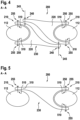
- FIG 15 is a diagram of a cross section of an illustrative pitch angle blocking device 200 with a connecting device 230 that non-rotatably connects first and second attachment means 210 in accordance with some embodiments.
- the illustrative pitch angle blocking device 200 of Figure 15 is similar to the pitch angle device 200 of Figure 14 in that it includes two struts 310 and a connecting device 230. However, contrary to the pitch angle blocking device 200 of Figure 14 , the pitch angle blocking device 200 of Figure 15 includes two struts that are attachable to opposite sides of the rotor blades 112.
- the two struts 310 and the connecting device 230 are integrally formed and form a single bigger strut that is attached to opposite sides of the first and second rotor blades 112.
- the single bigger strut may be attached to the upper portion of the first rotor blade 112 and to the lower portion of the second rotor blade 112.
- the single bigger strut may be attached to the lower portion of the first rotor blade 112 and to the upper portion of the second rotor blade 112.
- the single bigger strut may correspond to the diagonally arranged bigger struts of the pitch angle blocking device 200 of Figure 13 .
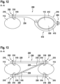
- FIG 16 is a diagram of a cross section of an illustrative pitch angle blocking device 200 with a connecting device 230 that non-rotatably connects first and second attachment means 210 in accordance with some embodiments.
- the illustrative pitch angle blocking device 200 includes two struts 310 and a connecting device 230.
- Fasteners 255 may be configured to non-rotatably and releasably attach the struts 310 to the first and second rotor blades 112.
- the first and second rotor blades 112 may include receiving means 510 for receiving the fasteners 255.
- the receiving means 510 may include holes, hooks, snap hooks, brackets, clamps, plates, or any combination thereof.
- the fasteners 255 may include attachment means for attaching the struts 310 to the receiving means 510 of the first and second rotor blades 112.
- the fasteners may include hooks or snap hooks that are hooked into holes of the first and second rotor blades 112.
- the receiving means 510 may include eyelets that are connected with hooks, snap hooks, or clamps of the fasteners 255.
- the connecting device 230 may include a first extension 220 that extends from the first attachment means 210. If desired, the connecting device 230 may include a second extension 220 that extends from the second attachment means 210.
- the connecting device 230 may include at least one interface connection 240 that connects the first extension 220 with the second extension 220.
- the at least one interface connection 240 may include a length adjustment device 320 that couples the first extension 220 with the second extension 220.
- the length adjustment device 320 may be configured to adjust a distance between the first extension 220 and the second extension 220.
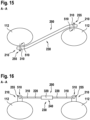
- FIG 17 is a diagram of a cross section of an illustrative pitch angle blocking device 200 with a connecting device 230 that non-rotatably connects first and second attachment means 210 in accordance with some embodiments.
- the illustrative pitch angle blocking device 200 of Figure 17 is similar to the pitch angle device 200 of Figure 16 in that it includes two struts 310 and a connecting device 230 that includes a length adjustment device 320.
- the pitch angle blocking device 200 of Figure 17 includes two struts 310 that are attachable to opposite sides of the rotor blades 112.
- first strut 310 may be attached to the upper portion of the first rotor blade 112, and the second strut 310 may be attached to the lower portion of the second rotor blade 112.
- first strut 310 may be attached to the lower portion of the first rotor blade 112, and the second strut 310 may be attached to the upper portion of the second rotor blade 112.
- Figure 18 is a three-dimensional diagram of an illustrative multi-blade rotor 110 of a rotary-wing aircraft (e.g., helicopter 100 of Figure 1 ).
- the multi-blade rotor 110 may be adapted to receiving a pitch angle blocking device 200 for blocking the pitch angle of the multi-blade rotor 110 in non-operational mode of the rotary-wing aircraft.
- the multi-blade rotor 110 includes a rotor hub 113 and neighboring first and second rotor blades 112 in circumferential direction 205 that extend from the rotor hub 113.
- the first rotor blade 112 includes first receiving means at a first location 520 that is spaced apart from the rotor hub 113 and configured to receiving at least a portion of a first attachment means 210 of the pitch angle blocking device 200.
- the second rotor blade 112 includes second receiving means at a second location 520 that is spaced apart from the rotor hub 113 and configured to receiving at least a portion of the second attachment means 210 of the pitch angle blocking device 200.
- the pitch angle blocking device 200 may include two brackets 250 and a connecting device 230.
- the two brackets 250 and the connecting device 230 may be integrally formed.
- Fasteners 255 may be configured to attach the two brackets 250 to the first and second rotor blades 112.
- the fasteners 255 may include pins in slots, slots on rails, or similarly aligned solutions to which the pitch angle blocking device 200 may be slid onto the first and second rotor blades 112 from the outside towards the rotor hub 113.
- the pitch angle blocking device 200 of Figure 13 is shown with three bigger struts: two bigger struts that are arranged horizontally, and one bigger strut that is arranged diagonally.
- the pitch angle blocking device 200 of Figure 13 may have one horizontally arranged bigger strut and two diagonally arranged bigger struts instead, if desired.
- the diagonally arranged bigger strut of Figure 13 is shown to have a smaller diameter than the horizontally arranged bigger struts.
- the diagonally arranged bigger strut may have the same diameter or a greater diameter than the horizontally arranged bigger struts.
- non-circular clamps 410 of Figures 10 to 12 are shown to have approximately elliptical shapes. However, the non-circular clamps 410 could have any other form of shape fitting with non-circular cross sections that are state of the art for transferring torsion loads.
- more than two degrees of freedom of a multi-blade rotor may be constrained, for example by applying an additional pitch angle blocking device between a different pair of rotor blades of the multi-blade rotor.
- the number of constrained degrees of freedom is more than the initial number of degrees of freedom without the pitch angle blocking devices, then one has to take care not to overload the elements of the pitch control system (e.g., by installing elastic elements at the locations of the fasteners).
Landscapes
- Engineering & Computer Science (AREA)
- Mechanical Engineering (AREA)
- Aviation & Aerospace Engineering (AREA)
- Transmission Devices (AREA)
- Wind Motors (AREA)
Claims (15)
- Dispositif (200) de blocage d'angle de pas pour bloquer l'angle de pas d'un rotor (110) multipales d'un aéronef (100) à voilure tournante dans un mode non-opérationnel de l'aéronef (100) à voilure tournante, le rotor (110) multipales ayant des première et seconde pales (112) de rotor, adjacentes suivant une direction (205) circonférentielle et qui s'étendent à partir d'un moyeu (113) de rotor, comprenant :un premier moyen (210) de fixation ;un second moyen (210) de fixation ; etun dispositif (230) de raccordement (230) qui raccorde sans pivotement possible le premier moyen (210) de fixation au second moyen de fixation (210),caractérisé en ce quele premier moyen (210) de fixation est configuré pour être fixé sans pivotement possible et de façon détachable à la première pale (112) de rotor et pour être espacé du moyeu (113) de rotor ; etle second moyen (210) de fixation est configuré pour être fixé à la seconde pale (112) de rotor et pour être espacé du moyeu (113) de rotor.
- Dispositif (200) de blocage d'angle de pas selon la revendication 1, dans lequel le premier moyen (210) de fixation comprend en outre :
au moins l'un parmi :un bras (310), et une attache (255) qui est configurée pour fixer sans pivotement possible et de façon détachable le bras (310) à la première pale (112) de rotor ;un demi-collier (250) qui enveloppe de part et d'autre au moins partiellement la première pale (112) de rotor, et au moins deux attaches (255) qui sont configurées pour fixer sans pivotement possible et de façon détachable le demi-collier (250) à la première pale (112) de rotor ; ouun collier (410) non circulaire avec des premier et second bras de serrage (412, 415) et une attache (255) qui est configurée pour fixer l'un à l'autre sans pivotement possible et de façon détachable les premier et second bras de serrage (412, 415) du collier (410) non circulaire de sorte que le collier (410) non circulaire enveloppe de part et d'autre la première pale (112) de rotor. - Dispositif (200) de blocage d'angle de pas selon la revendication 2, dans lequel le second moyen (210) de fixation comprend en outre :
au moins l'un parmi :un bras (310) supplémentaire, et une attache (255) supplémentaire qui est configurée pour fixer sans pivotement possible et de façon détachable le bras (310) supplémentaire à la seconde pale (112) de rotor ;un demi-collier (250) supplémentaire qui enveloppe de part et d'autre au moins partiellement la seconde pale (112) de rotor, et au moins deux attaches (255) supplémentaires qui sont configurées pour fixer sans pivotement possible et de façon détachable le demi-collier (250) supplémentaire à la seconde pale (112) de rotor ; ouun collier (410) non circulaire supplémentaire avec des premier et second bras de serrage (412,415) et une attache (255) supplémentaire qui est configurée pour fixer l'un à l'autre sans pivotement possible et de façon détachable les premier et second bras de serrage (412,415) du collier (410) non circulaire supplémentaire de sorte que le collier (410) non circulaire enveloppe de part et d'autre la seconde pale (112) de rotor. - Dispositif (200) de blocage d'angle de pas selon la revendication 3, dans lequel l'attache (255) et l'attache (255) supplémentaire comprennent au moins l'un parmi une tige filetée, un écrou, un boulon, une broche, une broche à libération rapide, un palier, une rondelle sphérique ou un élément élastique.
- Dispositif (200) de blocage d'angle de pas selon la revendication 3, dans lequel ledit au moins un parmi le bras (310), le demi-collier (250), ou le collier (410) non circulaire, le bras (310) supplémentaire, le demi-collier (250) supplémentaire, ou le collier (410) non circulaire supplémentaire, et le dispositif (230) de raccordement forment une partie intégrale.
- Dispositif (200) de blocage d'angle de pas selon l'une quelconque des revendications 1 à 4, dans lequel le dispositif (230) de raccordement comprend en outre :un premier prolongement (220) qui s'étend à partir du premier moyen (210) de fixation ; etun second prolongement (220) qui s'étend à partir du second moyen (210) de fixation.
- Dispositif (200) de blocage d'angle de pas selon la revendication 6, dans lequel le dispositif (230) de raccordement comprend en outre :
au moins un raccordement (240) d'interface qui raccorde le premier prolongement (220) à au moins l'un parmi le second moyen (210) de fixation ou le second prolongement (220). - Dispositif (200) de blocage d'angle de pas selon la revendication 7, dans lequel ledit au moins un raccordement (240) d'interface comprend en outre :
un dispositif (320) de réglage de la longueur qui relie le premier prolongement (220) audit au moins un parmi le second moyen (210) de fixation ou le second prolongement (220) et qui est configuré pour régler une distance entre le premier prolongement (220) et ledit au moins un parmi le second moyen (210) de fixation ou le second prolongement (220). - Dispositif (200) de blocage d'angle de pas selon la revendication 7, dans lequel ledit au moins un raccordement (240) d'interface comprend en outre :
au moins une attache (245) d'interface qui relie le premier prolongement (220) audit au moins un parmi le second moyen (210) de fixation ou le second prolongement (220). - Dispositif (200) de blocage d'angle de pas selon la revendication 9, dans lequel ladite au moins une attache (245) d'interface comprend au moins l'un parmi une vis, un écrou et une vis, une tige filetée ou un rivet.
- Dispositif (200) de blocage d'angle de pas selon la revendication 9, dans lequel ledit au moins un raccordement (240) d'interface comprend en outre :
une fente (248) dans le premier prolongement (220) à travers laquelle ladite au moins une attache (245) d'interface est apte à coulisser afin de permettre un déplacement du premier prolongement (220) par rapport à l'un parmi le second moyen (210) de fixation ou le second prolongement (220). - Rotor (110) multipales d'un aéronef (100) à voilure tournante comprenant :le dispositif (200) de blocage d'angle de pas selon l'une quelconque des revendications précédentes pour bloquer l'angle de pas du rotor (110) multipales dans un mode non-opérationnel de l'aéronef (100) à voilure tournante ;un moyeu (113) de rotor ; etdes première et seconde pales (112) de rotor adjacentes suivant une direction (205) circonférentielle qui s'étendent à partir du moyeu (113) de rotor, dans lequel la première pale (112) de rotor comprend un premier moyen (510) récepteur à un premier emplacement (520) qui est espacé du moyeu (113) de rotor et configuré pour accueillir au moins une partie du premier moyen (210) de fixation du dispositif (200) de blocage d'angle de pas ; et la seconde pale (112) de rotor comprend un second moyen (510) récepteur à un second emplacement (520) qui est espacé du moyeu (113) de rotor et configuré pour accueillir au moins une partie du second moyen (210) de fixation du dispositif (200) de blocage d'angle de pas.
- Rotor (110) multipales selon la revendication 12, dans lequel le premier moyen (510) récepteur comprend au moins l'un parmi une tige filetée, un palier, un élément élastique, un trou fileté ou un trou non fileté.
- Rotor (110) multipales selon la revendication 12 ou 13, dans lequel le second moyen (510) récepteur comprend une section transversale non circulaire de la seconde pale (112) de rotor au second emplacement (520).
- Aéronef (100) à voilure tournante comprenant un rotor (110) multipales selon l'une quelconque des revendications 12 à 14.
Priority Applications (2)
| Application Number | Priority Date | Filing Date | Title |
|---|---|---|---|
| EP20400027.7A EP4015364B1 (fr) | 2020-12-18 | 2020-12-18 | Dispositif de blocage de l'angle de pas |
| US17/445,130 US12060149B2 (en) | 2020-12-18 | 2021-08-16 | Pitch angle blocking device |
Applications Claiming Priority (1)
| Application Number | Priority Date | Filing Date | Title |
|---|---|---|---|
| EP20400027.7A EP4015364B1 (fr) | 2020-12-18 | 2020-12-18 | Dispositif de blocage de l'angle de pas |
Publications (2)
| Publication Number | Publication Date |
|---|---|
| EP4015364A1 EP4015364A1 (fr) | 2022-06-22 |
| EP4015364B1 true EP4015364B1 (fr) | 2023-09-27 |
Family
ID=74668601
Family Applications (1)
| Application Number | Title | Priority Date | Filing Date |
|---|---|---|---|
| EP20400027.7A Active EP4015364B1 (fr) | 2020-12-18 | 2020-12-18 | Dispositif de blocage de l'angle de pas |
Country Status (2)
| Country | Link |
|---|---|
| US (1) | US12060149B2 (fr) |
| EP (1) | EP4015364B1 (fr) |
Family Cites Families (9)
| Publication number | Priority date | Publication date | Assignee | Title |
|---|---|---|---|---|
| US3153455A (en) | 1962-10-15 | 1964-10-20 | Boeing Co | Folding mechanism |
| US4284387A (en) | 1979-05-02 | 1981-08-18 | United Technologies Corp. | Blade fold restraint system |
| US5322415A (en) | 1992-11-18 | 1994-06-21 | United Technologies Corporation | Pitch actuation system restraint device for a helicopter blade folding system |
| FR2750948B1 (fr) | 1996-07-12 | 1998-10-30 | Eurocopter France | Dispositif de blocage, au moins en pas, des pales d'un rotor |
| FR2836889B1 (fr) | 2002-03-11 | 2004-05-28 | Eurocopter France | Procede et dispositif de repliage-depliage des pales d'un rotor de giravion |
| US7207519B2 (en) * | 2004-03-03 | 2007-04-24 | Peter Hoynash | Blade restraint system |
| US7798442B2 (en) | 2006-03-17 | 2010-09-21 | Sikorsky Aircraft Corporation | Rotor assemblies having automatic blade folding systems |
| US7744349B1 (en) | 2006-09-11 | 2010-06-29 | Davis Aircraft Products Co., Inc. | Blade flap locking for out-of-use helicopters |
| US10457422B2 (en) * | 2016-12-07 | 2019-10-29 | Sikorsky Aircraft Corporation | Weights for water immersion testing |
-
2020
- 2020-12-18 EP EP20400027.7A patent/EP4015364B1/fr active Active
-
2021
- 2021-08-16 US US17/445,130 patent/US12060149B2/en active Active
Also Published As
| Publication number | Publication date |
|---|---|
| US20220194570A1 (en) | 2022-06-23 |
| EP4015364A1 (fr) | 2022-06-22 |
| US12060149B2 (en) | 2024-08-13 |
Similar Documents
| Publication | Publication Date | Title |
|---|---|---|
| EP0311155B1 (fr) | Montage antivibration d'un moteur | |
| US8342444B2 (en) | Fail safe extended torque box strut-to-wing mount | |
| US10723450B2 (en) | Passive pitch angle adjustment apparatus | |
| EP3560832B1 (fr) | Extensions d'ailes pliables pour aéronef | |
| EP3604130B1 (fr) | Système et procédé de rotation d'un rotor d'un aéronef à rotors basculants | |
| US10858096B1 (en) | Folding horn concept for rigid rotor blade fold | |
| US11661178B2 (en) | Tail rotor gearbox support assemblies for helicopters | |
| JPH08504143A (ja) | ヘリコプタ翼の折りたたみシステム用ピッチ起動システム拘束装置 | |
| US10336445B2 (en) | High flapping yoke hub assembly using a cylindrical elastomeric attachment to avoid holes | |
| US20160200432A1 (en) | Weight efficient servo attachment scheme for rigid coaxial rotor control system | |
| EP4015364B1 (fr) | Dispositif de blocage de l'angle de pas | |
| EP4261134A1 (fr) | Système de fixation de moteur pour aéronef et procédé de fixation de moteur | |
| US20190185150A1 (en) | Split yoke in a folding rotor blade assembly | |
| CA3055737C (fr) | Fixation servant a suspendre un moteur d'aeronef | |
| EP4541713B1 (fr) | Dispositif de service au sol pour fixer des pales de rotor d'un aéronef à voilure tournante | |
| US10787244B2 (en) | Semi-automatic rotor blade fold mechanism | |
| CN115246478B (zh) | 具有折叠机构的飞行器 | |
| EP4640566A1 (fr) | Aéronef à voilure tournante avec au moins une interface de fixation |
Legal Events
| Date | Code | Title | Description |
|---|---|---|---|
| PUAI | Public reference made under article 153(3) epc to a published international application that has entered the european phase |
Free format text: ORIGINAL CODE: 0009012 |
|
| STAA | Information on the status of an ep patent application or granted ep patent |
Free format text: STATUS: THE APPLICATION HAS BEEN PUBLISHED |
|
| STAA | Information on the status of an ep patent application or granted ep patent |
Free format text: STATUS: REQUEST FOR EXAMINATION WAS MADE |
|
| AK | Designated contracting states |
Kind code of ref document: A1 Designated state(s): AL AT BE BG CH CY CZ DE DK EE ES FI FR GB GR HR HU IE IS IT LI LT LU LV MC MK MT NL NO PL PT RO RS SE SI SK SM TR |
|
| 17P | Request for examination filed |
Effective date: 20220525 |
|
| RBV | Designated contracting states (corrected) |
Designated state(s): AL AT BE BG CH CY CZ DE DK EE ES FI FR GB GR HR HU IE IS IT LI LT LU LV MC MK MT NL NO PL PT RO RS SE SI SK SM TR |
|
| REG | Reference to a national code |
Ref country code: DE Ref legal event code: R079 Free format text: PREVIOUS MAIN CLASS: B64C0011320000 Ipc: B64C0027320000 Ref country code: DE Ref legal event code: R079 Ref document number: 602020018250 Country of ref document: DE Free format text: PREVIOUS MAIN CLASS: B64C0011320000 Ipc: B64C0027320000 |
|
| RIC1 | Information provided on ipc code assigned before grant |
Ipc: B64C 27/06 20060101ALN20230504BHEP Ipc: B64C 11/32 20060101ALN20230504BHEP Ipc: B63H 1/06 20060101ALN20230504BHEP Ipc: B64C 27/50 20060101ALI20230504BHEP Ipc: B64C 27/32 20060101AFI20230504BHEP |
|
| GRAP | Despatch of communication of intention to grant a patent |
Free format text: ORIGINAL CODE: EPIDOSNIGR1 |
|
| STAA | Information on the status of an ep patent application or granted ep patent |
Free format text: STATUS: GRANT OF PATENT IS INTENDED |
|
| RIC1 | Information provided on ipc code assigned before grant |
Ipc: B64C 27/06 20060101ALN20230511BHEP Ipc: B64C 11/32 20060101ALN20230511BHEP Ipc: B63H 1/06 20060101ALN20230511BHEP Ipc: B64C 27/50 20060101ALI20230511BHEP Ipc: B64C 27/32 20060101AFI20230511BHEP |
|
| RIC1 | Information provided on ipc code assigned before grant |
Ipc: B64C 27/06 20060101ALN20230523BHEP Ipc: B64C 11/32 20060101ALN20230523BHEP Ipc: B63H 1/06 20060101ALN20230523BHEP Ipc: B64C 27/50 20060101ALI20230523BHEP Ipc: B64C 27/32 20060101AFI20230523BHEP |
|
| RIC1 | Information provided on ipc code assigned before grant |
Ipc: B64C 27/06 20060101ALN20230530BHEP Ipc: B64C 11/32 20060101ALN20230530BHEP Ipc: B63H 1/06 20060101ALN20230530BHEP Ipc: B64C 27/50 20060101ALI20230530BHEP Ipc: B64C 27/32 20060101AFI20230530BHEP |
|
| INTG | Intention to grant announced |
Effective date: 20230614 |
|
| P01 | Opt-out of the competence of the unified patent court (upc) registered |
Effective date: 20230530 |
|
| RIN1 | Information on inventor provided before grant (corrected) |
Inventor name: BAUER, MARKUS Inventor name: KAHL, BERNWARD Inventor name: BUESING, MORITZ |
|
| GRAS | Grant fee paid |
Free format text: ORIGINAL CODE: EPIDOSNIGR3 |
|
| GRAA | (expected) grant |
Free format text: ORIGINAL CODE: 0009210 |
|
| STAA | Information on the status of an ep patent application or granted ep patent |
Free format text: STATUS: THE PATENT HAS BEEN GRANTED |
|
| AK | Designated contracting states |
Kind code of ref document: B1 Designated state(s): AL AT BE BG CH CY CZ DE DK EE ES FI FR GB GR HR HU IE IS IT LI LT LU LV MC MK MT NL NO PL PT RO RS SE SI SK SM TR |
|
| REG | Reference to a national code |
Ref country code: GB Ref legal event code: FG4D |
|
| REG | Reference to a national code |
Ref country code: CH Ref legal event code: EP |
|
| REG | Reference to a national code |
Ref country code: DE Ref legal event code: R096 Ref document number: 602020018250 Country of ref document: DE |
|
| REG | Reference to a national code |
Ref country code: IE Ref legal event code: FG4D |
|
| REG | Reference to a national code |
Ref country code: LT Ref legal event code: MG9D |
|
| PG25 | Lapsed in a contracting state [announced via postgrant information from national office to epo] |
Ref country code: GR Free format text: LAPSE BECAUSE OF FAILURE TO SUBMIT A TRANSLATION OF THE DESCRIPTION OR TO PAY THE FEE WITHIN THE PRESCRIBED TIME-LIMIT Effective date: 20231228 |
|
| PG25 | Lapsed in a contracting state [announced via postgrant information from national office to epo] |
Ref country code: SE Free format text: LAPSE BECAUSE OF FAILURE TO SUBMIT A TRANSLATION OF THE DESCRIPTION OR TO PAY THE FEE WITHIN THE PRESCRIBED TIME-LIMIT Effective date: 20230927 Ref country code: RS Free format text: LAPSE BECAUSE OF FAILURE TO SUBMIT A TRANSLATION OF THE DESCRIPTION OR TO PAY THE FEE WITHIN THE PRESCRIBED TIME-LIMIT Effective date: 20230927 Ref country code: NO Free format text: LAPSE BECAUSE OF FAILURE TO SUBMIT A TRANSLATION OF THE DESCRIPTION OR TO PAY THE FEE WITHIN THE PRESCRIBED TIME-LIMIT Effective date: 20231227 Ref country code: LV Free format text: LAPSE BECAUSE OF FAILURE TO SUBMIT A TRANSLATION OF THE DESCRIPTION OR TO PAY THE FEE WITHIN THE PRESCRIBED TIME-LIMIT Effective date: 20230927 Ref country code: LT Free format text: LAPSE BECAUSE OF FAILURE TO SUBMIT A TRANSLATION OF THE DESCRIPTION OR TO PAY THE FEE WITHIN THE PRESCRIBED TIME-LIMIT Effective date: 20230927 Ref country code: HR Free format text: LAPSE BECAUSE OF FAILURE TO SUBMIT A TRANSLATION OF THE DESCRIPTION OR TO PAY THE FEE WITHIN THE PRESCRIBED TIME-LIMIT Effective date: 20230927 Ref country code: GR Free format text: LAPSE BECAUSE OF FAILURE TO SUBMIT A TRANSLATION OF THE DESCRIPTION OR TO PAY THE FEE WITHIN THE PRESCRIBED TIME-LIMIT Effective date: 20231228 Ref country code: FI Free format text: LAPSE BECAUSE OF FAILURE TO SUBMIT A TRANSLATION OF THE DESCRIPTION OR TO PAY THE FEE WITHIN THE PRESCRIBED TIME-LIMIT Effective date: 20230927 |
|
| REG | Reference to a national code |
Ref country code: NL Ref legal event code: MP Effective date: 20230927 |
|
| REG | Reference to a national code |
Ref country code: AT Ref legal event code: MK05 Ref document number: 1615182 Country of ref document: AT Kind code of ref document: T Effective date: 20230927 |
|
| PG25 | Lapsed in a contracting state [announced via postgrant information from national office to epo] |
Ref country code: NL Free format text: LAPSE BECAUSE OF FAILURE TO SUBMIT A TRANSLATION OF THE DESCRIPTION OR TO PAY THE FEE WITHIN THE PRESCRIBED TIME-LIMIT Effective date: 20230927 |
|
| PG25 | Lapsed in a contracting state [announced via postgrant information from national office to epo] |
Ref country code: IS Free format text: LAPSE BECAUSE OF FAILURE TO SUBMIT A TRANSLATION OF THE DESCRIPTION OR TO PAY THE FEE WITHIN THE PRESCRIBED TIME-LIMIT Effective date: 20240127 |
|
| PG25 | Lapsed in a contracting state [announced via postgrant information from national office to epo] |
Ref country code: AT Free format text: LAPSE BECAUSE OF FAILURE TO SUBMIT A TRANSLATION OF THE DESCRIPTION OR TO PAY THE FEE WITHIN THE PRESCRIBED TIME-LIMIT Effective date: 20230927 |
|
| PG25 | Lapsed in a contracting state [announced via postgrant information from national office to epo] |
Ref country code: ES Free format text: LAPSE BECAUSE OF FAILURE TO SUBMIT A TRANSLATION OF THE DESCRIPTION OR TO PAY THE FEE WITHIN THE PRESCRIBED TIME-LIMIT Effective date: 20230927 |
|
| PG25 | Lapsed in a contracting state [announced via postgrant information from national office to epo] |
Ref country code: SM Free format text: LAPSE BECAUSE OF FAILURE TO SUBMIT A TRANSLATION OF THE DESCRIPTION OR TO PAY THE FEE WITHIN THE PRESCRIBED TIME-LIMIT Effective date: 20230927 Ref country code: RO Free format text: LAPSE BECAUSE OF FAILURE TO SUBMIT A TRANSLATION OF THE DESCRIPTION OR TO PAY THE FEE WITHIN THE PRESCRIBED TIME-LIMIT Effective date: 20230927 Ref country code: IS Free format text: LAPSE BECAUSE OF FAILURE TO SUBMIT A TRANSLATION OF THE DESCRIPTION OR TO PAY THE FEE WITHIN THE PRESCRIBED TIME-LIMIT Effective date: 20240127 Ref country code: ES Free format text: LAPSE BECAUSE OF FAILURE TO SUBMIT A TRANSLATION OF THE DESCRIPTION OR TO PAY THE FEE WITHIN THE PRESCRIBED TIME-LIMIT Effective date: 20230927 Ref country code: EE Free format text: LAPSE BECAUSE OF FAILURE TO SUBMIT A TRANSLATION OF THE DESCRIPTION OR TO PAY THE FEE WITHIN THE PRESCRIBED TIME-LIMIT Effective date: 20230927 Ref country code: CZ Free format text: LAPSE BECAUSE OF FAILURE TO SUBMIT A TRANSLATION OF THE DESCRIPTION OR TO PAY THE FEE WITHIN THE PRESCRIBED TIME-LIMIT Effective date: 20230927 Ref country code: AT Free format text: LAPSE BECAUSE OF FAILURE TO SUBMIT A TRANSLATION OF THE DESCRIPTION OR TO PAY THE FEE WITHIN THE PRESCRIBED TIME-LIMIT Effective date: 20230927 Ref country code: SK Free format text: LAPSE BECAUSE OF FAILURE TO SUBMIT A TRANSLATION OF THE DESCRIPTION OR TO PAY THE FEE WITHIN THE PRESCRIBED TIME-LIMIT Effective date: 20230927 Ref country code: PT Free format text: LAPSE BECAUSE OF FAILURE TO SUBMIT A TRANSLATION OF THE DESCRIPTION OR TO PAY THE FEE WITHIN THE PRESCRIBED TIME-LIMIT Effective date: 20240129 |
|
| PG25 | Lapsed in a contracting state [announced via postgrant information from national office to epo] |
Ref country code: PL Free format text: LAPSE BECAUSE OF FAILURE TO SUBMIT A TRANSLATION OF THE DESCRIPTION OR TO PAY THE FEE WITHIN THE PRESCRIBED TIME-LIMIT Effective date: 20230927 |
|
| REG | Reference to a national code |
Ref country code: DE Ref legal event code: R097 Ref document number: 602020018250 Country of ref document: DE |
|
| PG25 | Lapsed in a contracting state [announced via postgrant information from national office to epo] |
Ref country code: DK Free format text: LAPSE BECAUSE OF FAILURE TO SUBMIT A TRANSLATION OF THE DESCRIPTION OR TO PAY THE FEE WITHIN THE PRESCRIBED TIME-LIMIT Effective date: 20230927 |
|
| PG25 | Lapsed in a contracting state [announced via postgrant information from national office to epo] |
Ref country code: DK Free format text: LAPSE BECAUSE OF FAILURE TO SUBMIT A TRANSLATION OF THE DESCRIPTION OR TO PAY THE FEE WITHIN THE PRESCRIBED TIME-LIMIT Effective date: 20230927 |
|
| REG | Reference to a national code |
Ref country code: CH Ref legal event code: PL |
|
| PLBE | No opposition filed within time limit |
Free format text: ORIGINAL CODE: 0009261 |
|
| STAA | Information on the status of an ep patent application or granted ep patent |
Free format text: STATUS: NO OPPOSITION FILED WITHIN TIME LIMIT |
|
| PG25 | Lapsed in a contracting state [announced via postgrant information from national office to epo] |
Ref country code: LU Free format text: LAPSE BECAUSE OF NON-PAYMENT OF DUE FEES Effective date: 20231218 |
|
| PG25 | Lapsed in a contracting state [announced via postgrant information from national office to epo] |
Ref country code: MC Free format text: LAPSE BECAUSE OF FAILURE TO SUBMIT A TRANSLATION OF THE DESCRIPTION OR TO PAY THE FEE WITHIN THE PRESCRIBED TIME-LIMIT Effective date: 20230927 |
|
| REG | Reference to a national code |
Ref country code: BE Ref legal event code: MM Effective date: 20231231 |
|
| PG25 | Lapsed in a contracting state [announced via postgrant information from national office to epo] |
Ref country code: MC Free format text: LAPSE BECAUSE OF FAILURE TO SUBMIT A TRANSLATION OF THE DESCRIPTION OR TO PAY THE FEE WITHIN THE PRESCRIBED TIME-LIMIT Effective date: 20230927 Ref country code: LU Free format text: LAPSE BECAUSE OF NON-PAYMENT OF DUE FEES Effective date: 20231218 |
|
| 26N | No opposition filed |
Effective date: 20240628 |
|
| REG | Reference to a national code |
Ref country code: IE Ref legal event code: MM4A |
|
| PG25 | Lapsed in a contracting state [announced via postgrant information from national office to epo] |
Ref country code: IE Free format text: LAPSE BECAUSE OF NON-PAYMENT OF DUE FEES Effective date: 20231218 |
|
| PG25 | Lapsed in a contracting state [announced via postgrant information from national office to epo] |
Ref country code: BE Free format text: LAPSE BECAUSE OF NON-PAYMENT OF DUE FEES Effective date: 20231231 |
|
| PG25 | Lapsed in a contracting state [announced via postgrant information from national office to epo] |
Ref country code: CH Free format text: LAPSE BECAUSE OF NON-PAYMENT OF DUE FEES Effective date: 20231231 |
|
| PG25 | Lapsed in a contracting state [announced via postgrant information from national office to epo] |
Ref country code: SI Free format text: LAPSE BECAUSE OF FAILURE TO SUBMIT A TRANSLATION OF THE DESCRIPTION OR TO PAY THE FEE WITHIN THE PRESCRIBED TIME-LIMIT Effective date: 20230927 |
|
| PG25 | Lapsed in a contracting state [announced via postgrant information from national office to epo] |
Ref country code: SI Free format text: LAPSE BECAUSE OF FAILURE TO SUBMIT A TRANSLATION OF THE DESCRIPTION OR TO PAY THE FEE WITHIN THE PRESCRIBED TIME-LIMIT Effective date: 20230927 Ref country code: IE Free format text: LAPSE BECAUSE OF NON-PAYMENT OF DUE FEES Effective date: 20231218 Ref country code: CH Free format text: LAPSE BECAUSE OF NON-PAYMENT OF DUE FEES Effective date: 20231231 Ref country code: BE Free format text: LAPSE BECAUSE OF NON-PAYMENT OF DUE FEES Effective date: 20231231 |
|
| PG25 | Lapsed in a contracting state [announced via postgrant information from national office to epo] |
Ref country code: BG Free format text: LAPSE BECAUSE OF FAILURE TO SUBMIT A TRANSLATION OF THE DESCRIPTION OR TO PAY THE FEE WITHIN THE PRESCRIBED TIME-LIMIT Effective date: 20230927 |
|
| PG25 | Lapsed in a contracting state [announced via postgrant information from national office to epo] |
Ref country code: BG Free format text: LAPSE BECAUSE OF FAILURE TO SUBMIT A TRANSLATION OF THE DESCRIPTION OR TO PAY THE FEE WITHIN THE PRESCRIBED TIME-LIMIT Effective date: 20230927 |
|
| PG25 | Lapsed in a contracting state [announced via postgrant information from national office to epo] |
Ref country code: CY Free format text: LAPSE BECAUSE OF FAILURE TO SUBMIT A TRANSLATION OF THE DESCRIPTION OR TO PAY THE FEE WITHIN THE PRESCRIBED TIME-LIMIT; INVALID AB INITIO Effective date: 20201218 |
|
| PG25 | Lapsed in a contracting state [announced via postgrant information from national office to epo] |
Ref country code: HU Free format text: LAPSE BECAUSE OF FAILURE TO SUBMIT A TRANSLATION OF THE DESCRIPTION OR TO PAY THE FEE WITHIN THE PRESCRIBED TIME-LIMIT; INVALID AB INITIO Effective date: 20201218 |
|
| PG25 | Lapsed in a contracting state [announced via postgrant information from national office to epo] |
Ref country code: TR Free format text: LAPSE BECAUSE OF FAILURE TO SUBMIT A TRANSLATION OF THE DESCRIPTION OR TO PAY THE FEE WITHIN THE PRESCRIBED TIME-LIMIT Effective date: 20230927 |
|
| PGFP | Annual fee paid to national office [announced via postgrant information from national office to epo] |
Ref country code: DE Payment date: 20251211 Year of fee payment: 6 |
|
| PGFP | Annual fee paid to national office [announced via postgrant information from national office to epo] |
Ref country code: GB Payment date: 20251219 Year of fee payment: 6 |
|
| PGFP | Annual fee paid to national office [announced via postgrant information from national office to epo] |
Ref country code: IT Payment date: 20251223 Year of fee payment: 6 |
|
| PGFP | Annual fee paid to national office [announced via postgrant information from national office to epo] |
Ref country code: FR Payment date: 20251229 Year of fee payment: 6 |