EP4015403A1 - Dispositif pour former un sachet tubulaire pourvu de mouleur interne - Google Patents
Dispositif pour former un sachet tubulaire pourvu de mouleur interne Download PDFInfo
- Publication number
- EP4015403A1 EP4015403A1 EP21215854.7A EP21215854A EP4015403A1 EP 4015403 A1 EP4015403 A1 EP 4015403A1 EP 21215854 A EP21215854 A EP 21215854A EP 4015403 A1 EP4015403 A1 EP 4015403A1
- Authority
- EP
- European Patent Office
- Prior art keywords
- shaping
- forming
- edge
- prism
- section
- Prior art date
- Legal status (The legal status is an assumption and is not a legal conclusion. Google has not performed a legal analysis and makes no representation as to the accuracy of the status listed.)
- Withdrawn
Links
- 238000007493 shaping process Methods 0.000 claims abstract description 116
- 239000000463 material Substances 0.000 claims abstract description 54
- 230000001154 acute effect Effects 0.000 claims description 3
- 239000005022 packaging material Substances 0.000 description 10
- 238000004806 packaging method and process Methods 0.000 description 8
- 238000004519 manufacturing process Methods 0.000 description 5
- 238000011161 development Methods 0.000 description 3
- 230000018109 developmental process Effects 0.000 description 3
- 230000000694 effects Effects 0.000 description 3
- 238000012423 maintenance Methods 0.000 description 3
- 229910052751 metal Inorganic materials 0.000 description 3
- 239000002184 metal Substances 0.000 description 3
- 238000000034 method Methods 0.000 description 3
- 239000000835 fiber Substances 0.000 description 2
- 239000011888 foil Substances 0.000 description 2
- 229910000831 Steel Inorganic materials 0.000 description 1
- 229910052782 aluminium Inorganic materials 0.000 description 1
- XAGFODPZIPBFFR-UHFFFAOYSA-N aluminium Chemical compound [Al] XAGFODPZIPBFFR-UHFFFAOYSA-N 0.000 description 1
- 238000013459 approach Methods 0.000 description 1
- 230000015572 biosynthetic process Effects 0.000 description 1
- 239000013590 bulk material Substances 0.000 description 1
- 239000012876 carrier material Substances 0.000 description 1
- 239000002131 composite material Substances 0.000 description 1
- 230000001419 dependent effect Effects 0.000 description 1
- 230000007613 environmental effect Effects 0.000 description 1
- 230000005484 gravity Effects 0.000 description 1
- 238000012545 processing Methods 0.000 description 1
- 238000007789 sealing Methods 0.000 description 1
- 239000011343 solid material Substances 0.000 description 1
- 239000010959 steel Substances 0.000 description 1
Images



Classifications
-
- B—PERFORMING OPERATIONS; TRANSPORTING
- B65—CONVEYING; PACKING; STORING; HANDLING THIN OR FILAMENTARY MATERIAL
- B65B—MACHINES, APPARATUS OR DEVICES FOR, OR METHODS OF, PACKAGING ARTICLES OR MATERIALS; UNPACKING
- B65B9/00—Enclosing successive articles, or quantities of material, e.g. liquids or semiliquids, in flat, folded, or tubular webs of flexible sheet material; Subdividing filled flexible tubes to form packages
- B65B9/10—Enclosing successive articles, or quantities of material, in preformed tubular webs, or in webs formed into tubes around filling nozzles, e.g. extruded tubular webs
- B65B9/20—Enclosing successive articles, or quantities of material, in preformed tubular webs, or in webs formed into tubes around filling nozzles, e.g. extruded tubular webs the webs being formed into tubes in situ around the filling nozzles
- B65B9/22—Forming shoulders; Tube formers
-
- B—PERFORMING OPERATIONS; TRANSPORTING
- B65—CONVEYING; PACKING; STORING; HANDLING THIN OR FILAMENTARY MATERIAL
- B65B—MACHINES, APPARATUS OR DEVICES FOR, OR METHODS OF, PACKAGING ARTICLES OR MATERIALS; UNPACKING
- B65B59/00—Arrangements to enable machines to handle articles of different sizes, to produce packages of different sizes, to vary the contents of packages, to handle different types of packaging material, or to give access for cleaning or maintenance purposes
- B65B59/001—Arrangements to enable adjustments related to the product to be packaged
-
- B—PERFORMING OPERATIONS; TRANSPORTING
- B65—CONVEYING; PACKING; STORING; HANDLING THIN OR FILAMENTARY MATERIAL
- B65B—MACHINES, APPARATUS OR DEVICES FOR, OR METHODS OF, PACKAGING ARTICLES OR MATERIALS; UNPACKING
- B65B59/00—Arrangements to enable machines to handle articles of different sizes, to produce packages of different sizes, to vary the contents of packages, to handle different types of packaging material, or to give access for cleaning or maintenance purposes
- B65B59/003—Arrangements to enable adjustments related to the packaging material
-
- B—PERFORMING OPERATIONS; TRANSPORTING
- B65—CONVEYING; PACKING; STORING; HANDLING THIN OR FILAMENTARY MATERIAL
- B65B—MACHINES, APPARATUS OR DEVICES FOR, OR METHODS OF, PACKAGING ARTICLES OR MATERIALS; UNPACKING
- B65B9/00—Enclosing successive articles, or quantities of material, e.g. liquids or semiliquids, in flat, folded, or tubular webs of flexible sheet material; Subdividing filled flexible tubes to form packages
- B65B9/06—Enclosing successive articles, or quantities of material, in a longitudinally-folded web, or in a web folded into a tube about the articles or quantities of material placed upon it
-
- B—PERFORMING OPERATIONS; TRANSPORTING
- B65—CONVEYING; PACKING; STORING; HANDLING THIN OR FILAMENTARY MATERIAL
- B65B—MACHINES, APPARATUS OR DEVICES FOR, OR METHODS OF, PACKAGING ARTICLES OR MATERIALS; UNPACKING
- B65B9/00—Enclosing successive articles, or quantities of material, e.g. liquids or semiliquids, in flat, folded, or tubular webs of flexible sheet material; Subdividing filled flexible tubes to form packages
- B65B9/10—Enclosing successive articles, or quantities of material, in preformed tubular webs, or in webs formed into tubes around filling nozzles, e.g. extruded tubular webs
- B65B9/20—Enclosing successive articles, or quantities of material, in preformed tubular webs, or in webs formed into tubes around filling nozzles, e.g. extruded tubular webs the webs being formed into tubes in situ around the filling nozzles
-
- B—PERFORMING OPERATIONS; TRANSPORTING
- B65—CONVEYING; PACKING; STORING; HANDLING THIN OR FILAMENTARY MATERIAL
- B65B—MACHINES, APPARATUS OR DEVICES FOR, OR METHODS OF, PACKAGING ARTICLES OR MATERIALS; UNPACKING
- B65B9/00—Enclosing successive articles, or quantities of material, e.g. liquids or semiliquids, in flat, folded, or tubular webs of flexible sheet material; Subdividing filled flexible tubes to form packages
- B65B9/06—Enclosing successive articles, or quantities of material, in a longitudinally-folded web, or in a web folded into a tube about the articles or quantities of material placed upon it
- B65B2009/063—Forming shoulders
Definitions
- the invention relates to a forming device for forming a tube from a material web, for form, fill and seal machines.
- the invention relates to shaping devices of this type which are designed to form tube cross-sections whose boundary lines exhibit locally large changes in their curvature.
- Vertical flow wrap machines are preferably used for packaging bulk goods in flow bags, whereas horizontal flow wrap machines are used in particular for packaging piece goods.
- the reshaping The process of converting the web of material from flat to tubular takes place inside the tubular bagging machine on a shaping device.
- Some shaping devices have a shoulder part with a shoulder surface on which the planar cross-section of the material web is first curved, and a prism part with a prism surface on which the curved cross-section is formed into a closed tubular cross-section.
- the shoulder surface and the prism surface are connected to one another along a three-dimensional forming edge.
- the forming device may be a one-piece or multi-piece three-dimensional body made of strong, unyielding material, made either from solid material or from sheet metal, usually from steel or another material.
- Adjustable shaping devices which are designed to produce different hose cross-sections, can have several shaping elements, each of which only has a section of the shoulder surface, forming edge and prism surface, with in particular straight forming edge sections, i.e. areas in which the boundary line of the hose cross-section to be produced is straight, not physically at all are realized.
- the web of packaging material is taken off a roll as a flat web and formed into a tube by means of the forming device.
- the tube can enclose a round, rectangular, or other convex-shaped cross-section.
- the geometry of the guide surface of the forming shoulder i.e. the surface that comes into contact with the web of packaging material, should be dimensioned and spatially designed in such a way that each fiber of the material Packaging material web travels the same path during forming and the distance between adjacent material fibers remains constant transversely to the running direction, so that the packaging material web is neither stretched nor lengthened nor permanently deformed.
- the packaging material (often bulk material) is often filled by gravity through a prismatic filling tube, which projects vertically into the prismatic part of the forming device, into the tube cross-section located in the prismatic part.
- a prismatic filling tube which protrudes horizontally into the prism part of the forming device, is sometimes used in a comparable manner in order to keep open the part of the formed tubular cross section located in the prism part while the packaged goods (often piece goods) are pushed into them becomes.
- the filling tube protrudes very far into the prism part in these cases, for example 100 mm, 200 mm or more.
- the filling tube is usually dimensioned in such a way that there is a sufficient distance, for example 10 to 20 times or more of the thickness of the material web, from the prism surface and from the forming edge of the forming device in order to carry out the forming and the not to impede the transport of the material web or to influence it in any other way. It follows from this that the forming of the material web into a tube cross-section is caused exclusively by the forming edge and the filling tube itself is not involved in this tube formation is.
- WO 2019/123356 A1 describes a forming device for horizontal tubular bagging machines for forming a tube from a web of material, which can be modified in a simple manner for the production of different bag cross sections.
- the shaping device comprises a horizontal base plate, which has a slot running in a transport direction, and two shoulder parts fastened to the base plate on either side of the slot, each of which has a section of a forming edge over which the material web is guided in a forming manner, the shoulder parts each comprise at least two detachably connected shoulder part segments, the distance between which can be adjusted by inserting one or more extension elements.
- a shaping device for forming a tube from a web of material, with a first forming region in which the web of material a straight web entry as far as a forming edge and is thereby formed from a flat into a curved state, a second forming region downstream of the first forming area, in which the material web is guided from the forming edge to a web outlet cross-section and thereby formed from a curved state into a tubular state which comprises the following: a base frame, two forming elements which are arranged next to one another on the base frame and are movably mounted at an angle to the transport direction of the material web, each with a forming edge segment.
- the shaping elements each comprise a first sub-element and a second sub-element, with the second sub-element abutting the first sub-element in a minimum position and the second sub-element in the direction of the forming edge segment, forming a gap in the forming edge that grows with increasing distance from the first sub-element up to a maximum position is adjustable.
- webs of material made from a wide variety of materials are used to produce tubular bags for packaging purposes.
- pure plastic foils are used, which can have one or more layers.
- Plastic foils can also be coated with metal, for example with aluminum.
- Composite materials can be based, for example, on paper as the carrier material and can also be additionally coated with metal and/or plastic. Paper-based packaging materials in particular are currently experiencing a renaissance in efforts to promote sustainability and environmental protection.
- All of these different packaging materials behave differently when they are formed from a flat web of material into a closed tubular cross-section.
- the respective tube-forming device and the packaging machine in which the tube-forming device is installed must be adapted to the currently used packaging material with regard to the angle at which the material web enters the tube-forming device, with regard to the web tension and, if necessary, with regard to the web running speed in such a way that a crease-free forming process is guaranteed and there are no folds or even tears in the material web. It has been shown that some paper-based packaging materials are particularly difficult to process when the tube cross-section has sections with strong curvature.
- one object of the present invention is to further develop known shaping devices for forming a tube from a material web, in particular such horizontal shaping devices for packaging piece goods, in such a way that they enable the production of tube cross-sections with greatly varying curvature of the boundary line of the tube cross-section in a simple and inexpensive way.
- the proposed forming device can be designed according to one or more of the aspects described below be. For the sake of clarity, their description is made with reference to the drawing figures, in which several of these aspects are realized. Each of these aspects is claimed both individually and in any combination.
- a shaping device for shaping a material web into a tube which has a shoulder part with a shoulder surface on which the flat cross section of the material web is initially curved, and a prism part with a prism surface on which the curved cross section forms a closed tube cross section is formed, wherein the shoulder surface and the prismatic surface are connected to one another along a three-dimensional forming edge, which has at least one forming edge section with a small curvature and at least one forming edge section with a strong curvature, wherein in the prism part, at least in the area of a forming edge section with a strong curvature, an inner forming element with one of the forming edge and the inner former surface facing the prism surface is arranged such that a gap running along the forming edge is formed between the prism surface and the inner former surface, the gap width of which is adjustable.
- the gap width represents the vertical distance of the inner former surface from the prism surface and thus from the forming edge.
- the gap is accordingly large enough to let the material web pass without it being pinched or otherwise impeded in its movement.
- the inner forming element helps to ensure an exact and crease-free forming by the packaging material is supported by the effect of the inner former surface in snuggling up in the forming edge area of strong curvature.
- the inner shaping element is arranged so that it can move relative to the shaping edge in such a way that the gap width is between two characteristic positions which have a maximum gap width (e.g. as a maintenance position for clearing jams or for introducing a new material web) and a minimum gap width (e.g. as a working position for the thinnest material web that can be processed with the shaping device).
- a maximum gap width e.g. as a maintenance position for clearing jams or for introducing a new material web
- a minimum gap width e.g. as a working position for the thinnest material web that can be processed with the shaping device.
- the proposed shaping device is designed in such a way that the inner shaping element can be fixed between the two characteristic positions named above at at least one intermediate position, for example at one of a plurality of intermediate positions.
- the inner shaping element can either be fixable in any desired intermediate position or the shaping device is designed in such a way that it has a number of discrete intermediate positions, for example by providing a grid which defines the intermediate positions at which the inner shaping element can be fixed.
- the inner shaping element can be movable perpendicularly to a longitudinal extent of the prism part, ie directly towards or away from the prism surface. This means that the interior former element to Increasing the width of the gap moves into the channel formed by the prism surface, which is required for the introduction of the packages into the tube cross-section formed.
- the inner shaping element is movably and at the same time elastically mounted in this direction, for example against the force of a restoring spring.
- the gap width is adjusted as needed and automatically, so to speak, in that the material web displaces the inner shaping element towards the center of the tube cross-section when the forming forces become so great that the material web, despite the support provided by the inner shaping element, is no longer able to move into to snuggle in a forming edge area with a strong curvature, for example because the thickness of the material web varies and a point of greater thickness passes the forming edge.
- the interior shaping element is moved back into its original position by the elastic bearing, for example a return spring.
- the inner former surface encloses an acute angle with the prismatic surface relative to a longitudinal axis of the prismatic surface and the inner former element is movable in the direction of the longitudinal axis is.
- the inner former element can be moved back and forth in the transport direction of the packaged goods and thus parallel to a longitudinal axis of the prism part to increase or decrease the gap between the inner former surface and the forming edge.
- the inner former element in addition to the movement in the transport direction of the packages, which causes an adjustment of the gap width of the gap formed between the inner former surface and the forming edge, is elastically mounted perpendicularly thereto, for example against the Force of a return spring to allow temporary adjustment of the gap width in the event of fluctuating forming forces, for example due to fluctuating material thickness of the material web.
- each inner shaping element is operatively connected to an actuator to generate the movement relative to the shaping edge.
- an actuator can be designed, for example, as an electromotive spindle drive, pneumatic cylinder or the like and can be particularly advantageously controlled by a machine controller of a packaging machine.
- the shaping edge has at least two shaping edge sections with a strong curvature, with an inner shaping element extending over the at least two Has Umformkantenabitese strong curvature extending inner former surface.
- An example of this is a shaping device that is designed to produce a rectangular tube cross-section, with the incoming web of material facing a straight deformed edge section, at each of whose two ends there is a deformed edge section with a strong curvature.
- An inner former element in the above-mentioned sense can, for example, have an inner former surface that extends both over the straight forming edge section and over the two adjacent forming edge sections with a strong curvature, so that the material web is guided and supported in this entire area between the inner former surface and the forming edge.
- the proposed shaping device can be provided with at least two shaping elements that can be moved relative to one another in order to set the tube cross section to be produced, each of which has a deformed edge section with a strong curvature, with an inner shaping element that is movably coupled to the shaping element being arranged in the region of the deformed edge section with a strong curvature is.
- the associated inner shaping element is carried along synchronously with each shaping element when the shaping device is adjusted to produce a different tube cross section.
- the inner shaping element remains movable relative to the shaping element in order to adjust the gap width, ie the gap For example, to increase to the maximum possible level when a new web of material has to be introduced, or to adjust the gap width to a thicker or thinner material of the packaging web.
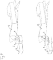
- a shaping element 12 of a shaping device 1 according to the invention with an inner shaping element 5 is shown in the upper drawing figure 1A.
- the lower drawing figure 1B shows a shaping element 12 of a known shaping device 1 of the prior art with a filling tube 8, which protrudes horizontally by the amount F into the prismatic part of the shaping device 1, by the tube cross-section during the filling of the tube with the packaged goods kept open, ie to prevent the collapse of the hose cross-section.
- a direct comparison of the drawing figures 1A and 1B with one another shows that the inner shaping element 5 does not protrude into the tube cross section, but merely has a direct geometric operative relationship to the forming edge 4 of the shaping element 12, in that there is a comparatively small gap between the inner shaping element 5 and the shaping edge 4 remains, the gap width of which in the exemplary embodiment is only about two to three times the thickness of the web of material, whereby the forming of the web of material into a closed cross section is effected jointly by the forming edge 4 and the inner former element 5 .
- the forming device is designed in such a way that it is designed to produce a rectangular tube cross-section.
- the deformed edge 4 therefore has deformed edge sections with a small curvature 41 and deformed edge sections with a strong curvature 42 .
- the inner shaping elements 5 are arranged and their inner shaping surfaces 51 are shaped in such a way that they follow the contour of the shaping edge 4 in the area of the corners of the tube cross-section and thus in shaping edge sections of greater curvature 42, so that together with the shaping edge 4 they are shaping onto the area between them act through guided material web.
- the inner former elements 5 are arranged so that they can be moved relative to the forming edge 4 in such a way that the gap width between the inner former surface 51 and the forming edge 4 can be adjusted.
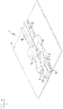
- the Figures 2 to 6 show in various representations an overall view of a first embodiment of a shaping device 1 of the proposed type in a perspective view, the shaping device with two characteristic positions of the inner shaping elements in a side view and in a perspective view and the geometric relationships on the shaping device in the two characteristic positions.
- Two shaping elements 12 are arranged on a base plate 11, which are shaped in such a way that a material web guided over them is shaped into a tubular cross-section. Lying on the base plate 11, objects to be packaged can be pushed into the shaped tubular cross-section.
- Front guide elements 13 are therefore arranged on the base plate 11 before the beginning of the forming area, which limit the transport path of the objects to be packaged.
- Rear guide elements 13 are arranged on the base plate 11 behind the two shaping elements 12 and guide the finished packaged objects along the transport path.
- two inner former elements 5 are arranged on the base plate 11 between the front guide elements 13 and the two forming elements 12 , each of which has an inner former surface 51 facing the forming edge 4 .
- Each of the two interior shaping elements 5 is mounted in a slot in the base plate 11 so that it can be displaced in the transport direction of the objects to be packaged and can be fixed in a desired position by means of a screw.
- the inner former elements 5 can be manually inserted into a characteristic Position are brought in which the gap width between the respective inner former surface 51 and the forming edge 4 has a maximum dimension.
- the inner shaping elements 5 can also be brought manually into a second characteristic position and fixed, in which the inner shaping surface 51 enters into a spatial relationship and operative connection with the forming edge 4, which guides and directs the material web, particularly in the forming edge areas of strong curvature 42 and in this way directly contributes to the forming of the material web into a tubular cross-section.
- the figure 5 and 6 show the geometric relationships on the proposed shaping device in different views.
- the inner forming element 5 is in a characteristic position, which is a working position.
- the adjustment path A1 of the inner shaping element 5 is maximum here, based on the guide element 13 .
- the gap width G1 is minimal in this position, so that the contribution of the inner shaping element 5 to the shaping of the material web into a tube cross section is at a maximum.
- the inner former member 5 is in a characteristic position which is a maintenance position.
- the adjustment path A2 of the inner shaping element 5 is minimal here, based on the guide element 13 .
- the gap width G2 is maximum in this position, so that the contribution of the inner former element 5 to the forming of the material web into a tube cross-section is minimal, unless this gap width was selected because a thicker material web is being processed, which requires a correspondingly larger gap width.
- the Figures 7 to 9 show in various representations an overall view of a second embodiment of a shaping device 1 of the proposed type in a perspective view, a perspective detailed view of the shaping device and the characteristic positions of the inner shaping elements of the shaping device in a perspective view.
- Two shaping elements 12 are arranged on a base plate 11, which are shaped in such a way that a material web 7 guided over them is shaped into a tubular cross-section. Lying on the base plate 11, objects to be packaged can be pushed into the shaped tubular cross-section.
- Front guide elements 13 are therefore arranged on the base plate 11 before the beginning of the forming area, which limit the transport path of the objects to be packaged.
- Rear guide elements 13 are arranged on the base plate 11 behind the two shaping elements 12 and guide the finished packaged objects along the transport path.
- two inner former elements 5 are arranged on the base plate 11 between the front guide elements 13 and the two forming elements 12 , each of which has an inner former surface 51 facing the forming edge 4 .
- Each of the two interior shaping elements 5 is mounted in a slot in the base plate 11 so that it can be displaced in the transport direction of the objects to be packaged.
- Two actuators 6 are arranged on the underside of the base plate 11, which are each operatively connected to one of the two inner forming elements 5 in such a way that the inner forming elements 5 can be moved towards or away from the forming edge 4 and can be fixed in a desired position by means of . This makes it possible for everyone Inner former element 5 to approach and fix the desired characteristic position without manual intervention, for example determined by a machine control.
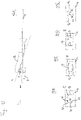
- FIG. 10 shows four examples of possible designs of the inner former elements 5, as well as the shape and arrangement of their inner former surfaces 51 relative to the forming elements 12 and the forming edge 4.
- the upper illustration 10A shows a side view in the viewing direction C and a sectional plane D, which points to the lower illustrations 10B to 10E have been used to explain possible configurations of inner former elements 5.
- FIG. Schematically shown therein are the base plate 11 and the two shaping elements 12, which are designed together to produce a rectangular tube cross section, which is composed of deformed edge sections with a small curvature 41 and deformed edge sections with a strong curvature 42.
- the configuration according to illustration 10B corresponds to the shape and arrangement of the interior shaping elements 5 of the exemplary embodiments already explained in FIG Figures 2 to 6 and 7 to 9 , in which two inner forming elements 5 each extend along a forming edge section of strong curvature 42 in the upper half of the tube cross section.
- An alternative embodiment is shown in illustration 10C, in which an inner former element 5 has an inner former surface 51 which, in the upper half of the hose cross section, extends over two corner regions with deformed edge sections of greater curvature 42 and a deformed edge section of lesser curvature 41 arranged in between.
- each inner former element 5 has an inner former surface 51, each of which extends in a lateral area of the hose cross section over two corner areas with deformed edge sections of greater curvature 42 and a deformed edge section of lesser curvature 41 arranged in between.
- Another alternative configuration is shown in illustration 10E, in which two inner former elements 5, each with an inner former surface 51, each extend along a forming edge section with a strong curvature 42 in the upper half of the tube cross section.
Landscapes
- Engineering & Computer Science (AREA)
- Mechanical Engineering (AREA)
- Containers And Plastic Fillers For Packaging (AREA)
Applications Claiming Priority (1)
| Application Number | Priority Date | Filing Date | Title |
|---|---|---|---|
| DE102020134431.7A DE102020134431A1 (de) | 2020-12-21 | 2020-12-21 | Schlauchbeutelformungseinrichtung mit Innenformer |
Publications (1)
| Publication Number | Publication Date |
|---|---|
| EP4015403A1 true EP4015403A1 (fr) | 2022-06-22 |
Family
ID=79230549
Family Applications (1)
| Application Number | Title | Priority Date | Filing Date |
|---|---|---|---|
| EP21215854.7A Withdrawn EP4015403A1 (fr) | 2020-12-21 | 2021-12-20 | Dispositif pour former un sachet tubulaire pourvu de mouleur interne |
Country Status (3)
| Country | Link |
|---|---|
| US (1) | US20220194640A1 (fr) |
| EP (1) | EP4015403A1 (fr) |
| DE (1) | DE102020134431A1 (fr) |
Families Citing this family (2)
| Publication number | Priority date | Publication date | Assignee | Title |
|---|---|---|---|---|
| IT202000014857A1 (it) * | 2020-06-22 | 2021-12-22 | Ilapak Int S A | Gruppo piegatore per la piegatura di un materiale in film a formare un involucro tubolare. |
| DE102023118754A1 (de) | 2023-07-14 | 2025-01-16 | Syntegon Packaging Systems Ag | Horizontalformvorrichtung, Verpackungsmaschine mit einer derartigen Horizontalformvorrichtung sowie Stützeinheit für eine derartige Horizontalformvorrichtung |
Citations (5)
| Publication number | Priority date | Publication date | Assignee | Title |
|---|---|---|---|---|
| DE69718744T2 (de) * | 1996-08-14 | 2003-07-10 | Fuji Photo Film Co., Ltd. | Maschine zum Herstellen kissenartiger Verpackungen |
| DE102005016703A1 (de) * | 2005-04-01 | 2006-10-05 | Drut, Henry, Dr. | Verstellbare Formschulter |
| WO2019123356A1 (fr) | 2017-12-20 | 2019-06-27 | Formerfab Gmbh | Dispositif de mise en forme pour ensacheuse soudeuse horizontale |
| WO2020058531A2 (fr) | 2018-09-21 | 2020-03-26 | Formerfab Gmbh | Dispositif de formage de sachets tubulaires |
| WO2022079268A1 (fr) * | 2020-10-16 | 2022-04-21 | Syntegon Packaging Systems Ag | Dispositif de mise en forme horizontal |
Family Cites Families (3)
| Publication number | Priority date | Publication date | Assignee | Title |
|---|---|---|---|---|
| JP2905223B2 (ja) | 1989-08-11 | 1999-06-14 | 株式会社川島製作所 | 縦型製袋充填包装機の万能製袋器 |
| DE102005019129A1 (de) | 2005-04-19 | 2006-10-26 | Drut, Henry, Dr. | Verfahren und Vorrichtung zur Herstellung eines Schlauchs |
| JP4766682B2 (ja) | 2006-03-29 | 2011-09-07 | 株式会社東京自働機械製作所 | 縦形製袋充填包装機の製袋装置 |
-
2020
- 2020-12-21 DE DE102020134431.7A patent/DE102020134431A1/de not_active Withdrawn
-
2021
- 2021-12-20 EP EP21215854.7A patent/EP4015403A1/fr not_active Withdrawn
- 2021-12-20 US US17/645,234 patent/US20220194640A1/en not_active Abandoned
Patent Citations (5)
| Publication number | Priority date | Publication date | Assignee | Title |
|---|---|---|---|---|
| DE69718744T2 (de) * | 1996-08-14 | 2003-07-10 | Fuji Photo Film Co., Ltd. | Maschine zum Herstellen kissenartiger Verpackungen |
| DE102005016703A1 (de) * | 2005-04-01 | 2006-10-05 | Drut, Henry, Dr. | Verstellbare Formschulter |
| WO2019123356A1 (fr) | 2017-12-20 | 2019-06-27 | Formerfab Gmbh | Dispositif de mise en forme pour ensacheuse soudeuse horizontale |
| WO2020058531A2 (fr) | 2018-09-21 | 2020-03-26 | Formerfab Gmbh | Dispositif de formage de sachets tubulaires |
| WO2022079268A1 (fr) * | 2020-10-16 | 2022-04-21 | Syntegon Packaging Systems Ag | Dispositif de mise en forme horizontal |
Also Published As
| Publication number | Publication date |
|---|---|
| DE102020134431A1 (de) | 2022-06-23 |
| US20220194640A1 (en) | 2022-06-23 |
Similar Documents
| Publication | Publication Date | Title |
|---|---|---|
| DE69600796T2 (de) | Maschine zum Verpacken von Gegenständen in einem, zu einem Schlauch umgeformten, Band | |
| DE69803525T2 (de) | Verfahren und Vorrichtung zum Formen eines Schlauches und Vorrichtung zur Herstellung von Verpackungsbehältern | |
| EP1675796A2 (fr) | Dispositif de depot d'une bande de materiau flexible | |
| EP4015403A1 (fr) | Dispositif pour former un sachet tubulaire pourvu de mouleur interne | |
| DE69621659T2 (de) | Bahn aus verpackungszuschnitten | |
| DE3881848T2 (de) | Faltvorrichtung. | |
| DE60000245T2 (de) | Verpackungsmaschine | |
| EP1105333A1 (fr) | Procede et dispositif de perforation de bandes de matiere | |
| DE4307143A1 (de) | Strahlgeschwindigkeitsbeeinflussung im Mehrschichtenstoffauflauf | |
| DE2024648C3 (de) | Faltapparat mit Transportwalzen für Materialbahnen | |
| EP2428453B1 (fr) | Procédé d'installation de bandes de cerclage autour de pièces d'emballage | |
| DE102005018111A1 (de) | Verfahren zum Abrollen von Bahnmaterial in einer Verpackungsmaschine und Verpackungsmaschine | |
| DE102006013858A1 (de) | Verstellbare Formungseinrichtung, insbesondere für horizontale Schlauchbeutelmaschinen | |
| EP3359478B1 (fr) | Courroie de pliage pour dispositif de pliage de découpes à plat de boîte pliante | |
| DE4119068A1 (de) | Einrichtung zur verbindung zweier trockengruppen einer papiermaschine | |
| DE1240891B (de) | Ausgabevorrichtung fuer blattfoermiges Material | |
| EP0522440A2 (fr) | Dispositif d'essai de l'étanchéité de gobelets fermés hermétiquement par une couvercle | |
| EP3990264B1 (fr) | Dispositif de façonnage pour le façonnage continuel | |
| DE102005016703A1 (de) | Verstellbare Formschulter | |
| DE2800262C3 (de) | Vorrichtung zum Abziehen einer flachgelegten Schlauchfolienbahn aus Kunststoff | |
| EP3662101B1 (fr) | Dispositif pour extraire un produit en forme de bande d'un métier à tisser | |
| DE3213572A1 (de) | Maschine zum planieren von saegeblaettern fuer bandsaegen | |
| DE4207183A1 (de) | Vorrichtung zum zufuehren von naehgut, insbesondere mit sich einrollenden kanten | |
| DE102005055209B3 (de) | Antriebseinrichtung für einen Streckhelfer zum mechanischen Verformen einer Kunststofffolie oder -platte | |
| DE1479931B2 (de) | Breitschlitzduese mit verstellbarer schlitzweite |
Legal Events
| Date | Code | Title | Description |
|---|---|---|---|
| PUAI | Public reference made under article 153(3) epc to a published international application that has entered the european phase |
Free format text: ORIGINAL CODE: 0009012 |
|
| STAA | Information on the status of an ep patent application or granted ep patent |
Free format text: STATUS: THE APPLICATION HAS BEEN PUBLISHED |
|
| AK | Designated contracting states |
Kind code of ref document: A1 Designated state(s): AL AT BE BG CH CY CZ DE DK EE ES FI FR GB GR HR HU IE IS IT LI LT LU LV MC MK MT NL NO PL PT RO RS SE SI SK SM TR |
|
| STAA | Information on the status of an ep patent application or granted ep patent |
Free format text: STATUS: REQUEST FOR EXAMINATION WAS MADE |
|
| 17P | Request for examination filed |
Effective date: 20220623 |
|
| RBV | Designated contracting states (corrected) |
Designated state(s): AL AT BE BG CH CY CZ DE DK EE ES FI FR GB GR HR HU IE IS IT LI LT LU LV MC MK MT NL NO PL PT RO RS SE SI SK SM TR |
|
| STAA | Information on the status of an ep patent application or granted ep patent |
Free format text: STATUS: EXAMINATION IS IN PROGRESS |
|
| 17Q | First examination report despatched |
Effective date: 20220905 |
|
| TPAC | Observations filed by third parties |
Free format text: ORIGINAL CODE: EPIDOSNTIPA |
|
| STAA | Information on the status of an ep patent application or granted ep patent |
Free format text: STATUS: THE APPLICATION IS DEEMED TO BE WITHDRAWN |
|
| 18D | Application deemed to be withdrawn |
Effective date: 20240702 |