EP4015433B1 - Dispositif de suspension de charge et engin de levage - Google Patents
Dispositif de suspension de charge et engin de levage Download PDFInfo
- Publication number
- EP4015433B1 EP4015433B1 EP21211855.8A EP21211855A EP4015433B1 EP 4015433 B1 EP4015433 B1 EP 4015433B1 EP 21211855 A EP21211855 A EP 21211855A EP 4015433 B1 EP4015433 B1 EP 4015433B1
- Authority
- EP
- European Patent Office
- Prior art keywords
- connecting element
- load suspension
- coupling structure
- load
- suspension means
- Prior art date
- Legal status (The legal status is an assumption and is not a legal conclusion. Google has not performed a legal analysis and makes no representation as to the accuracy of the status listed.)
- Active
Links
Images




Classifications
-
- B—PERFORMING OPERATIONS; TRANSPORTING
- B66—HOISTING; LIFTING; HAULING
- B66C—CRANES; LOAD-ENGAGING ELEMENTS OR DEVICES FOR CRANES, CAPSTANS, WINCHES, OR TACKLES
- B66C1/00—Load-engaging elements or devices attached to lifting or lowering gear of cranes or adapted for connection therewith for transmitting lifting forces to articles or groups of articles
- B66C1/10—Load-engaging elements or devices attached to lifting or lowering gear of cranes or adapted for connection therewith for transmitting lifting forces to articles or groups of articles by mechanical means
Definitions
- the invention relates to a load handling device for a hoist.
- Supporting means are generally understood to mean devices that are permanently connected to the hoist for receiving load handling equipment, slings or loads.
- Slings are generally understood to mean devices that do not belong to the hoist and that create a connection between the suspension means and the load or the suspension means and load handling equipment.
- the lifting assembly comprises an upper part and a number of independent lower parts, the upper part comprising a lifting beam, a suspension assembly for suspending the lifting beam from a crane hook, and a latching assembly comprising an actuator assembly.
- the latch assembly is intended to engage the top with a bottom.
- a base includes a lifting tool intended to be connected to a load and a latching interface intended to be engaged with the latch assembly of the top.
- the latch assembly is attached to the lifting beam and includes side plates intended to contain the actuator assembly, the side plates including through holes intended to receive linear actuators of the actuator assembly.
- an adapter for a hoist for handling load handling devices with a hoist-side first coupling element is known.
- the coupling element can be arranged on a traction device or on a suspension device.
- a second coupling element on the load-carrying means side is provided, which can be arranged on the load-carrying means, it being possible for the first and the second coupling element to enter into a releasable non-positive and positive connection with one another.
- the cross-sectional profile of the profile rails consists of two hook-shaped sections arranged in mirror image to the longitudinal center line and the two profile rails form a hollow box, the top and bottom of which are formed by two of the end regions of the hook-shaped sections of the cross-sectional profile pointing towards one another.
- the invention is based on the object of specifying a load handling device for a hoist that is improved compared to the prior art and an improved hoist.
- the load handling device according to the invention for a hoist comprises at least one load handling device, in particular a traverse, with at least one load handling device coupling structure and at least one connecting element.
- the connecting element comprises at least one stop means and/or at least one fastening structure for a stop means and at least one second connecting element coupling structure which is complementary to the load handling device coupling structure.
- the connecting element is or can be fastened to the load-carrying means in a detachable, non-destructive manner and the second connecting element-coupling structure is in mechanical engagement with the load-carrying means-coupling structure when the connecting element is in the fastened state on the load-carrying means.
- a large number of functions can be implemented due to the possible optional coupling of a load handling device with different connecting elements each comprising at least one sling and/or at least one fastening structure for a sling.
- various connecting elements can be selected from a modular system.
- a load handling device can be used for different applications different fasteners are used. This results in significant cost savings and resource savings, in addition to a reduction in the storage space required for the load handling device, in particular compared to load handling devices on which the slings are firmly welded to the load handling device.
- the load handling device coupling structure and the second connecting element coupling structure enables a mechanical key-lock principle to be implemented.
- the load handling device coupling structure and the first connecting element coupling structure are designed and shaped in particular in such a way that the connecting element can be mounted on the load receiving device in a fixed, predetermined number of positions relative to one another, so that assembly errors and the resulting operational hazards can be avoided.
- the at least one connecting element has at least one second connecting element coupling structure that is congruent with the load handling device coupling structure. This makes it possible for another connecting element to be able to be fastened to a connecting element with its first connecting element coupling structure.
- the material projection and the material recess have a round or an oval or a triangular or a quadrangular cross section and thus enable simple and intuitive positioning of the connecting element on the load handling device.
- a respective diameter of the material projection and the material recess increases continuously or non-linearly, in particular exponentially, starting from a head of the material projection to a foot of the same and starting from a bottom of the material recess to an opening of the same.
- the occurrence of mechanical stress peaks and/or their size can be reduced, in particular in the case of the exponential increase, in the assembled state of the material projection in the material recess.
- the material projection and the material recess are formed in a common molded part, the molded part being non-positively, materially and/or positively fastened in a complementary opening of a connecting element body.
- the load handling device depending on the material of the connecting element, it can also be designed as a homogeneous and one-piece molded part, in particular without joints, with the molded part being designed, for example, as a deep-drawn part, extruded part, cast part, pressed part, injection-molded part or sintered part .
- the load handling device comprises a plurality of load handling device bores arranged in a defined pattern and at a defined distance from the load handling device coupling structure, and the connecting element comprises a number of connecting element bores formed in a congruent pattern.
- a screw or a bolt is guided or can be guided through corresponding load-carrying means bores and connecting element bores, by means of which the connecting element is screwed or can be screwed to the load-carrying means.
- the load handling device bore can also be designed as a threaded bore, for example.
- the bores enable the connecting element to be fastened to the load-receiving means in a simple and reliable manner so that it can be detached in a non-destructive manner.
- the patterns and distances are designed differently depending on the application and/or permissible carrying capacity of the load-carrying device, so that incorrect assembly of connecting elements with, for example, a lower carrying capacity on load-carrying devices with, for example, a higher carrying capacity can be reliably avoided.
- connection between the connecting elements is designed in particular analogously to the previously described connection between the connecting element and the load handling device and has corresponding advantages.
- the connecting elements connected in series are fastened jointly to the load-carrying means by means of screws or bolts passed through all of the connecting element bores.
- the hoist according to the invention comprises at least one aforementioned load handling device.
- the hoist is characterized by a large number of functions due to the configuration of the load-carrying device, in which an optional coupling of a load-carrying device with different connecting elements, each comprising at least one sling and/or at least one fastening structure for a sling, is possible.
- various connecting elements can be selected from a modular system.
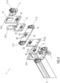
- FIG 1 a possible embodiment of a load handling device 1 according to the invention for a hoist, for example for a crane, is shown.
- the figures 2 and 3 show perspective views of different sections of the load handling device 1 for clarification.
- the load-carrying device 1 comprises a load-carrying means 2, which is designed as a so-called traverse.
- the load-carrying means 2 comprises a plurality of attachment means 3.1 to 3.8, which are provided for coupling the load-carrying means 2 to a carrying means 4, for example a hook of a crane.
- These attachment means 3.1 to 3.8 have an essentially unchangeable position on the load handling device 2.
- a number of these fixed stop means 3.1 to 3.8 can vary in any way.
- the load-carrying means 2 does not include such fixed attachment means 3.1 to 3.8.
- the load-carrying means 2 comprises a further fixed fastening structure 6.4 designed as a toothing, a further fastening structure 6.5 that can be variably positioned on this fastening structure 6.4 and a further attachment means 5.5 arranged on this fastening structure 6.5, which is used to couple the load-carrying means 2 to other attachment means and/or not shown. or a load to be moved.
- the load-carrying means 2 comprises a further attachment structure 6.6 and another attachment means 5.5 arranged on this attachment structure 6.6, which is designed to couple the load-carrying means 2 to other attachment means (not shown) and/or a load to be moved.
- a number of such stop means 5.4, 5.5 and such attachment structures 6.4 to 6.6 can vary in any way.
- the load-carrying means 2 does not include such attachment means 5.4, 5.5 and attachment structures 6.4 to 6.6.
- the load handling device 2 comprises at least one load handling device coupling structure 7, 8, in the exemplary embodiment shown a coupling structure 7, 8 on each end face, to which a plurality of connecting elements 9 to 15 can be mechanically coupled.
- the load-carrying means coupling structures 7, 8 are each non-positively, materially and/or positively attached to the load-carrying means 2, for example welded.
- the load handling device 1 comprises at least one connecting element 9 to 15, seven connecting elements 9 to 15 in the exemplary embodiment shown.
- the connecting elements 9 to 15 each have at least one stop means 16.1 to 16.3, 17.1 to 17.4 and/or at least one fastening structure 18 for a sling 16.1 to 16.3, 17.1 to 17.4.
- the slinging means 16.1 to 16.3 are provided for coupling the load-carrying means 2 to a carrying means 4, for example a hook of a crane, and/or other slinging means, not shown.
- the slinging means 17.1 to 17.4 are designed to couple the load-carrying means 2 to other slinging means (not shown) and/or a load to be moved.
- the connecting elements 9 to 15 are also at least essentially plate-shaped, with the first connecting element coupling structures 19 each being arranged on a flat side of the respective connecting element 9 to 15 .
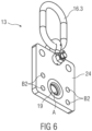
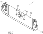
- the connecting elements 9 to 15 comprise a plurality of connecting element bores B2 formed in a congruent pattern for the load handling device bores B1, which are shown in FIGS figures 1 and 2 are not provided with reference numbers. These are in figure 3 example of the connecting element 14 and in the Figures 4 to 8 shown for the connecting elements 11 to 15.
- a screw 20 is guided through the mutually corresponding load suspension device bores B1 and connecting element bores B2, by means of which and exactly one connecting element 9 to 15 is screwed to the respective load handling device 2 by means of a screw nut 21 .
- the respective connecting element 9 to 15 is non-destructively detachably attached to the load handling device 2 and the first connecting element coupling structure 19 is in the attached state of the connecting element 9 to 15 on the load handling device 2 in mechanical engagement with the load handling device coupling structure 7, 8.
- the load handling devices are -Coupling structure 7, 8 and the connecting element coupling structure 19 are designed in such a way that the mechanical engagement between the second connecting element coupling structure 19 and the load handling device coupling structure 7, 8 is positive and/or non-positive.
- the connecting elements 9 to 11 and 13 to 15 have a side opposite the first connecting element coupling structure 19 that is congruent with the load handling device coupling structure 7, 8 second connecting element coupling structure 22, so that between two immediately adjacent connecting elements 9 to 15 the first connecting element coupling structure 19 of a connecting element 9 to 15 is mechanically engaged with the second connecting element coupling structure 22 of the immediately adjacent connecting element 9 to 11, 13 to 15 stands.
- the second connecting element coupling structures 22 in figure 1 not provided with reference numbers.
- first connecting element coupling structure 19 and the second connecting element coupling structure 22, in particular the material projection V and the material recess A, are formed in a common molded part 23, which is in the Figures 9 and 10 is shown in more detail.
- connection element body 24 shown in more detail fuel, fuel and/or fastened in a form-fitting manner, for example pressed and/or welded and/or screwed into a thread.
- figure 4 shows the connecting element 11 with a stop means 17.4 designed as a hook in a perspective view.
- figure 6 shows the connecting element 13 with a stop means 16.3 designed as a ring in a perspective view.
- figure 8 shows the connecting element 13 with a fastening structure 18 comprising a plurality of bores in a perspective view.
- the molded part 23 shown is connected to a corresponding body, not shown in detail, analogously to the connecting element body 24 in order to produce the load handling device coupling structure 7 , 8 .
Landscapes
- Engineering & Computer Science (AREA)
- Mechanical Engineering (AREA)
- Load-Engaging Elements For Cranes (AREA)
- Forklifts And Lifting Vehicles (AREA)
- Warehouses Or Storage Devices (AREA)
Claims (9)
- Dispositif de réception de charge (1) destiné à un treuil de levage, ledit dispositif comprenant- au moins un moyen de réception de charge (2), notamment une traverse, comprenant au moins une structure d'accouplement de moyen de réception de charge (7, 8) et- au moins un élément de liaison (9 à 15) qui comprend- au moins un moyen de butée (16.1 à 16.3, 17.1 à 17.4) et/ou au moins une structure de fixation (18) destinée à un moyen de butée (16.1 à 16.3, 17.1 à 17.4),- au moins une première structure d'accouplement d'élément de liaison (19) complémentaire de la structure d'accouplement de moyen de réception de charge (7, 8),- l'élément de liaison (9 à 15) étant ou pouvant être fixé de manière amovible et non destructive au moyen de réception de charge (2) et la première structure d'accouplement d'élément de liaison (19) étant en engagement mécanique avec la structure d'accouplement de moyen de réception de charge (7, 8) lorsque l'élément de liaison (9 à 15) est fixé au moyen de réception de charge (2),- l'au moins un élément de liaison (9 à 15) comprenant une deuxième structure d'accouplement d'élément de liaison (22) congruente avec la structure d'accouplement de moyen de réception de charge (7, 8),caractérisé en ce que
l'élément de liaison (9 à 15) est au moins sensiblement en forme de plaque,- la première structure d'accouplement d'élément de liaison (19) et la deuxième structure d'accouplement d'élément de liaison (22) étant disposées ou conçues sur des côtés plats opposés de l'élément de liaison (9 à 15). - Dispositif de réception de charge (1) selon la revendication 1, l'engagement mécanique entre la première structure d'accouplement d'élément de liaison (19) et la structure d'accouplement de moyen de réception de charge (7, 8) étant une liaison par complémentarité de formes et/ou une liaison en force.
- Dispositif de réception de charge (1) selon l'une des revendications précédentes,- les structures d'accouplement de moyen de réception de charge (7, 8) comportant chacune une saillie de matière (V) et- la première structure d'accouplement d'élément de liaison (19) comportant un évidement de matière (A) complémentaire de la saillie de matière (V).
- Dispositif de réception de charge (1) selon la revendication 3, la saillie de matière (V) et l'évidement de matière (A) ayant une section transversale ronde ou ovale ou triangulaire ou quadrangulaire.
- Dispositif de réception de charge (1) selon la revendication 4, une dimension respective, notamment un diamètre respectif, de la saillie de matière (V) et de l'évidement de matière (A) depuis une tête de la saillie de matière (V) jusqu'à un pied de celle-ci et depuis un fond de l'évidement de matière (A) à une ouverture de celui-ci augmentant au moins par portions de manière continue ou non linéaire, en particulier de manière exponentielle.
- Dispositif de réception de charge (1) selon l'une des revendications 3 à 6,- la saillie de matière (V) et l'évidement de matière (A) étant formés dans une pièce moulée commune (23) et- la pièce moulée (23) étant fixée dans une ouverture, complémentaire de celle-ci, d'un corps d'élément de liaison (24) par une liaison par complémentarité de formes, une liaison en force et/ou une liaison de matière.
- Dispositif de réception de charge (1) selon l'une des revendications précédentes,- le moyen de réception de charge (2) comprenant une pluralité d'alésages de moyen de réception de charge (B1) qui sont disposés selon un schéma défini et à une distance définie de la structure d'accouplement de moyen de réception de charge (7, 8),- l'élément de liaison (9 à 15) comprenant une pluralité d'alésages d'élément de liaison (B2) formés selon un motif congruent et- une vis (20) ou un boulon, qui permettent à l'élément de liaison (9 à 15) d'être ou de pouvant être vissé au moyen de réception de charge (2), étant ou pouvant être guidés à travers des alésages de moyen de réception de charge (B1) et des trous d'élément de liaison (B2) qui correspondent les uns aux autres.
- Dispositif de réception de charge (1) selon l'une des revendications précédentes,- plusieurs éléments de liaison (9 à 15) étant disposés les uns derrière les autres et- entre deux éléments de liaison (9 à 15) directement adjacents, la première structure d'accouplement d'élément de liaison (19) d'un élément de liaison (9 à 15) étant en engagement mécanique avec la deuxième structure d'accouplement d'élément de liaison (22) de l'élément de liaison (9 à 15) directement adjacent.
- Treuil de levage, comprenant au moins un dispositif de réception de charge (1) selon l'une quelconque des revendications précédentes.
Applications Claiming Priority (1)
| Application Number | Priority Date | Filing Date | Title |
|---|---|---|---|
| DE102020215896.7A DE102020215896B4 (de) | 2020-12-15 | 2020-12-15 | Lastaufnahmeeinrichtung und Hebezeug |
Publications (3)
| Publication Number | Publication Date |
|---|---|
| EP4015433A1 EP4015433A1 (fr) | 2022-06-22 |
| EP4015433B1 true EP4015433B1 (fr) | 2023-09-06 |
| EP4015433C0 EP4015433C0 (fr) | 2023-09-06 |
Family
ID=78821495
Family Applications (1)
| Application Number | Title | Priority Date | Filing Date |
|---|---|---|---|
| EP21211855.8A Active EP4015433B1 (fr) | 2020-12-15 | 2021-12-02 | Dispositif de suspension de charge et engin de levage |
Country Status (4)
| Country | Link |
|---|---|
| EP (1) | EP4015433B1 (fr) |
| DE (1) | DE102020215896B4 (fr) |
| ES (1) | ES2967271T3 (fr) |
| PL (1) | PL4015433T3 (fr) |
Family Cites Families (5)
| Publication number | Priority date | Publication date | Assignee | Title |
|---|---|---|---|---|
| US3206243A (en) * | 1962-12-03 | 1965-09-14 | Boyd F Miles | Spreader bar |
| DE9306542U1 (de) | 1993-04-30 | 1993-07-01 | Carl Stahl GmbH, 7334 Süßen | Lasttraverse |
| GB0604569D0 (en) * | 2006-03-07 | 2006-04-19 | Modulift Design & Consulting L | A spreader assembly |
| DE102014017550A1 (de) | 2014-11-28 | 2016-06-02 | Axzion Gks Stahl Und Maschinenbau Gmbh | Adapter für Lastaufnahmeeinrichtungen |
| DE102016222211A1 (de) | 2016-11-11 | 2018-05-17 | Siemens Aktiengesellschaft | Hebeanordnung |
-
2020
- 2020-12-15 DE DE102020215896.7A patent/DE102020215896B4/de not_active Expired - Fee Related
-
2021
- 2021-12-02 ES ES21211855T patent/ES2967271T3/es active Active
- 2021-12-02 PL PL21211855.8T patent/PL4015433T3/pl unknown
- 2021-12-02 EP EP21211855.8A patent/EP4015433B1/fr active Active
Also Published As
| Publication number | Publication date |
|---|---|
| DE102020215896B4 (de) | 2023-03-02 |
| EP4015433C0 (fr) | 2023-09-06 |
| DE102020215896A1 (de) | 2022-06-15 |
| EP4015433A1 (fr) | 2022-06-22 |
| ES2967271T3 (es) | 2024-04-29 |
| PL4015433T3 (pl) | 2024-03-18 |
Similar Documents
| Publication | Publication Date | Title |
|---|---|---|
| EP2690312A1 (fr) | Dispositif de serrage pour chaînes | |
| DE19929966A1 (de) | Sicherungssystem für einen Bolzen und eine Mutter | |
| WO2010046376A1 (fr) | Structure de fixation, dispositif de fixation et système de fixation d’un composant d’équipement dans un aéronef | |
| DE3517620C2 (de) | Plastik-Clip | |
| WO2008125076A1 (fr) | Ressort à lame constitué d'un matériau composite fibres-matière plastique et élément d'application d'une force pour ce ressort | |
| EP1188936A2 (fr) | Assemblage de connection pour la fixation amovible de deux éléments | |
| EP1809441B1 (fr) | Dispositif de serrage et de prehension, en particulier pince lineaire ou centrale | |
| DE2231267C3 (de) | Metallendabschluß für Litzen und SeUe | |
| DE102020215896B4 (de) | Lastaufnahmeeinrichtung und Hebezeug | |
| DE112019004011T5 (de) | Montagesystem für ein Kastenprofil | |
| EP3299332B1 (fr) | Patte d'arrêt ou d'arrimage, support de fixation pour une patte d'arrêt ou d'arrimage ainsi que point d'arrêt ou d'arrimage pourvue d'une patte d'arrêt ou d'arrimage et support de fixation | |
| DE102021111609A1 (de) | Befestigungsvorrichtung zur lösbaren Verbindung mit einer Lochschiene eines Flugzeugs und Montageverfahren | |
| CH713884B1 (de) | System zur werkzeuglosen Befestigung eines Stellantriebs an einem Ventilflansch sowie geeigneter Stellantrieb. | |
| DD151432A5 (de) | Kettenfoerderer | |
| EP3819645A1 (fr) | Élément de renfort permettant de renforcer un système de contacteur d'essai, utilisation et procédé de montage d'un système de contacteur d'essai | |
| DE102012112362B3 (de) | Ventil mit einer Befestigungseinrichtung | |
| DE3304603C2 (de) | Bauteil, insbesondere Schäkel | |
| DE4239482C2 (de) | Verkürzungsorgan für Gliederketten | |
| EP0583580A2 (fr) | Articulation à chape | |
| EP3344419B1 (fr) | Visseuse dynamométrique | |
| EP3222464B1 (fr) | Système de cadre pour carrosseries de véhicules automobiles | |
| DE202008017524U1 (de) | Anbauelement zum Festlegen in einer oder mehreren T-Nuten | |
| DE4339670C2 (de) | Verriegelungssystem für Wechselgeräte zur Verwendung bei Lastkraftwagen sowie Element zur Verwendung bei einem derartigen System | |
| DE102021128633A1 (de) | Steckverbindergehäuse mit Verriegelungszapfen | |
| EP0163909A2 (fr) | Dispositif pour lever une charge |
Legal Events
| Date | Code | Title | Description |
|---|---|---|---|
| PUAI | Public reference made under article 153(3) epc to a published international application that has entered the european phase |
Free format text: ORIGINAL CODE: 0009012 |
|
| STAA | Information on the status of an ep patent application or granted ep patent |
Free format text: STATUS: THE APPLICATION HAS BEEN PUBLISHED |
|
| AK | Designated contracting states |
Kind code of ref document: A1 Designated state(s): AL AT BE BG CH CY CZ DE DK EE ES FI FR GB GR HR HU IE IS IT LI LT LU LV MC MK MT NL NO PL PT RO RS SE SI SK SM TR |
|
| STAA | Information on the status of an ep patent application or granted ep patent |
Free format text: STATUS: REQUEST FOR EXAMINATION WAS MADE |
|
| 17P | Request for examination filed |
Effective date: 20221115 |
|
| RBV | Designated contracting states (corrected) |
Designated state(s): AL AT BE BG CH CY CZ DE DK EE ES FI FR GB GR HR HU IE IS IT LI LT LU LV MC MK MT NL NO PL PT RO RS SE SI SK SM TR |
|
| GRAJ | Information related to disapproval of communication of intention to grant by the applicant or resumption of examination proceedings by the epo deleted |
Free format text: ORIGINAL CODE: EPIDOSDIGR1 |
|
| STAA | Information on the status of an ep patent application or granted ep patent |
Free format text: STATUS: GRANT OF PATENT IS INTENDED |
|
| GRAP | Despatch of communication of intention to grant a patent |
Free format text: ORIGINAL CODE: EPIDOSNIGR1 |
|
| INTG | Intention to grant announced |
Effective date: 20230411 |
|
| GRAS | Grant fee paid |
Free format text: ORIGINAL CODE: EPIDOSNIGR3 |
|
| GRAA | (expected) grant |
Free format text: ORIGINAL CODE: 0009210 |
|
| STAA | Information on the status of an ep patent application or granted ep patent |
Free format text: STATUS: THE PATENT HAS BEEN GRANTED |
|
| AK | Designated contracting states |
Kind code of ref document: B1 Designated state(s): AL AT BE BG CH CY CZ DE DK EE ES FI FR GB GR HR HU IE IS IT LI LT LU LV MC MK MT NL NO PL PT RO RS SE SI SK SM TR |
|
| REG | Reference to a national code |
Ref country code: GB Ref legal event code: FG4D Free format text: NOT ENGLISH |
|
| REG | Reference to a national code |
Ref country code: CH Ref legal event code: EP |
|
| REG | Reference to a national code |
Ref country code: DE Ref legal event code: R096 Ref document number: 502021001437 Country of ref document: DE |
|
| REG | Reference to a national code |
Ref country code: IE Ref legal event code: FG4D Free format text: LANGUAGE OF EP DOCUMENT: GERMAN |
|
| U01 | Request for unitary effect filed |
Effective date: 20230921 |
|
| U07 | Unitary effect registered |
Designated state(s): AT BE BG DE DK EE FI FR IT LT LU LV MT NL PT SE SI Effective date: 20230929 |
|
| U20 | Renewal fee for the european patent with unitary effect paid |
Year of fee payment: 3 Effective date: 20231128 |
|
| PG25 | Lapsed in a contracting state [announced via postgrant information from national office to epo] |
Ref country code: GR Free format text: LAPSE BECAUSE OF FAILURE TO SUBMIT A TRANSLATION OF THE DESCRIPTION OR TO PAY THE FEE WITHIN THE PRESCRIBED TIME-LIMIT Effective date: 20231207 |
|
| PG25 | Lapsed in a contracting state [announced via postgrant information from national office to epo] |
Ref country code: RS Free format text: LAPSE BECAUSE OF FAILURE TO SUBMIT A TRANSLATION OF THE DESCRIPTION OR TO PAY THE FEE WITHIN THE PRESCRIBED TIME-LIMIT Effective date: 20230906 Ref country code: NO Free format text: LAPSE BECAUSE OF FAILURE TO SUBMIT A TRANSLATION OF THE DESCRIPTION OR TO PAY THE FEE WITHIN THE PRESCRIBED TIME-LIMIT Effective date: 20231206 Ref country code: HR Free format text: LAPSE BECAUSE OF FAILURE TO SUBMIT A TRANSLATION OF THE DESCRIPTION OR TO PAY THE FEE WITHIN THE PRESCRIBED TIME-LIMIT Effective date: 20230906 Ref country code: GR Free format text: LAPSE BECAUSE OF FAILURE TO SUBMIT A TRANSLATION OF THE DESCRIPTION OR TO PAY THE FEE WITHIN THE PRESCRIBED TIME-LIMIT Effective date: 20231207 |
|
| PG25 | Lapsed in a contracting state [announced via postgrant information from national office to epo] |
Ref country code: IS Free format text: LAPSE BECAUSE OF FAILURE TO SUBMIT A TRANSLATION OF THE DESCRIPTION OR TO PAY THE FEE WITHIN THE PRESCRIBED TIME-LIMIT Effective date: 20240106 |
|
| REG | Reference to a national code |
Ref country code: ES Ref legal event code: FG2A Ref document number: 2967271 Country of ref document: ES Kind code of ref document: T3 Effective date: 20240429 |
|
| PG25 | Lapsed in a contracting state [announced via postgrant information from national office to epo] |
Ref country code: SM Free format text: LAPSE BECAUSE OF FAILURE TO SUBMIT A TRANSLATION OF THE DESCRIPTION OR TO PAY THE FEE WITHIN THE PRESCRIBED TIME-LIMIT Effective date: 20230906 Ref country code: RO Free format text: LAPSE BECAUSE OF FAILURE TO SUBMIT A TRANSLATION OF THE DESCRIPTION OR TO PAY THE FEE WITHIN THE PRESCRIBED TIME-LIMIT Effective date: 20230906 Ref country code: IS Free format text: LAPSE BECAUSE OF FAILURE TO SUBMIT A TRANSLATION OF THE DESCRIPTION OR TO PAY THE FEE WITHIN THE PRESCRIBED TIME-LIMIT Effective date: 20240106 Ref country code: CZ Free format text: LAPSE BECAUSE OF FAILURE TO SUBMIT A TRANSLATION OF THE DESCRIPTION OR TO PAY THE FEE WITHIN THE PRESCRIBED TIME-LIMIT Effective date: 20230906 Ref country code: SK Free format text: LAPSE BECAUSE OF FAILURE TO SUBMIT A TRANSLATION OF THE DESCRIPTION OR TO PAY THE FEE WITHIN THE PRESCRIBED TIME-LIMIT Effective date: 20230906 |
|
| REG | Reference to a national code |
Ref country code: DE Ref legal event code: R097 Ref document number: 502021001437 Country of ref document: DE |
|
| PLBE | No opposition filed within time limit |
Free format text: ORIGINAL CODE: 0009261 |
|
| STAA | Information on the status of an ep patent application or granted ep patent |
Free format text: STATUS: NO OPPOSITION FILED WITHIN TIME LIMIT |
|
| 26N | No opposition filed |
Effective date: 20240607 |
|
| PG25 | Lapsed in a contracting state [announced via postgrant information from national office to epo] |
Ref country code: MC Free format text: LAPSE BECAUSE OF FAILURE TO SUBMIT A TRANSLATION OF THE DESCRIPTION OR TO PAY THE FEE WITHIN THE PRESCRIBED TIME-LIMIT Effective date: 20230906 |
|
| PG25 | Lapsed in a contracting state [announced via postgrant information from national office to epo] |
Ref country code: MC Free format text: LAPSE BECAUSE OF FAILURE TO SUBMIT A TRANSLATION OF THE DESCRIPTION OR TO PAY THE FEE WITHIN THE PRESCRIBED TIME-LIMIT Effective date: 20230906 |
|
| REG | Reference to a national code |
Ref country code: IE Ref legal event code: MM4A |
|
| PG25 | Lapsed in a contracting state [announced via postgrant information from national office to epo] |
Ref country code: IE Free format text: LAPSE BECAUSE OF NON-PAYMENT OF DUE FEES Effective date: 20231202 |
|
| PG25 | Lapsed in a contracting state [announced via postgrant information from national office to epo] |
Ref country code: IE Free format text: LAPSE BECAUSE OF NON-PAYMENT OF DUE FEES Effective date: 20231202 |
|
| U21 | Renewal fee for the european patent with unitary effect paid with additional fee |
Year of fee payment: 4 Effective date: 20250218 |
|
| PG25 | Lapsed in a contracting state [announced via postgrant information from national office to epo] |
Ref country code: CY Free format text: LAPSE BECAUSE OF FAILURE TO SUBMIT A TRANSLATION OF THE DESCRIPTION OR TO PAY THE FEE WITHIN THE PRESCRIBED TIME-LIMIT; INVALID AB INITIO Effective date: 20211202 |
|
| REG | Reference to a national code |
Ref country code: CH Ref legal event code: PL |
|
| PG25 | Lapsed in a contracting state [announced via postgrant information from national office to epo] |
Ref country code: CH Free format text: LAPSE BECAUSE OF NON-PAYMENT OF DUE FEES Effective date: 20241231 |
|
| U20 | Renewal fee for the european patent with unitary effect paid |
Year of fee payment: 5 Effective date: 20251027 |
|
| PG25 | Lapsed in a contracting state [announced via postgrant information from national office to epo] |
Ref country code: TR Free format text: LAPSE BECAUSE OF FAILURE TO SUBMIT A TRANSLATION OF THE DESCRIPTION OR TO PAY THE FEE WITHIN THE PRESCRIBED TIME-LIMIT Effective date: 20230906 |
|
| PGFP | Annual fee paid to national office [announced via postgrant information from national office to epo] |
Ref country code: PL Payment date: 20251119 Year of fee payment: 5 |
|
| PGFP | Annual fee paid to national office [announced via postgrant information from national office to epo] |
Ref country code: ES Payment date: 20260119 Year of fee payment: 5 |
|
| PG25 | Lapsed in a contracting state [announced via postgrant information from national office to epo] |
Ref country code: HU Free format text: LAPSE BECAUSE OF FAILURE TO SUBMIT A TRANSLATION OF THE DESCRIPTION OR TO PAY THE FEE WITHIN THE PRESCRIBED TIME-LIMIT; INVALID AB INITIO Effective date: 20211202 |