EP4015683A1 - Procédé de surveillance du processus de filage sur un dispositif de filage, poste de filage d'un métier à filer à air ainsi que dispositif de filage - Google Patents
Procédé de surveillance du processus de filage sur un dispositif de filage, poste de filage d'un métier à filer à air ainsi que dispositif de filage Download PDFInfo
- Publication number
- EP4015683A1 EP4015683A1 EP20215384.7A EP20215384A EP4015683A1 EP 4015683 A1 EP4015683 A1 EP 4015683A1 EP 20215384 A EP20215384 A EP 20215384A EP 4015683 A1 EP4015683 A1 EP 4015683A1
- Authority
- EP
- European Patent Office
- Prior art keywords
- spinning
- thread
- cone
- electrodes
- gap
- Prior art date
- Legal status (The legal status is an assumption and is not a legal conclusion. Google has not performed a legal analysis and makes no representation as to the accuracy of the status listed.)
- Granted
Links
Images

Classifications
-
- D—TEXTILES; PAPER
- D01—NATURAL OR MAN-MADE THREADS OR FIBRES; SPINNING
- D01H—SPINNING OR TWISTING
- D01H1/00—Spinning or twisting machines in which the product is wound-up continuously
- D01H1/11—Spinning by false-twisting
- D01H1/115—Spinning by false-twisting using pneumatic means
-
- D—TEXTILES; PAPER
- D01—NATURAL OR MAN-MADE THREADS OR FIBRES; SPINNING
- D01H—SPINNING OR TWISTING
- D01H13/00—Other common constructional features, details or accessories
- D01H13/32—Counting, measuring, recording or registering devices
-
- D—TEXTILES; PAPER
- D01—NATURAL OR MAN-MADE THREADS OR FIBRES; SPINNING
- D01H—SPINNING OR TWISTING
- D01H13/00—Other common constructional features, details or accessories
- D01H13/14—Warning or safety devices, e.g. automatic fault detectors, stop motions ; Monitoring the entanglement of slivers in drafting arrangements
- D01H13/22—Warning or safety devices, e.g. automatic fault detectors, stop motions ; Monitoring the entanglement of slivers in drafting arrangements responsive to presence of irregularities in running material
-
- D—TEXTILES; PAPER
- D01—NATURAL OR MAN-MADE THREADS OR FIBRES; SPINNING
- D01H—SPINNING OR TWISTING
- D01H13/00—Other common constructional features, details or accessories
- D01H13/26—Arrangements facilitating the inspection or testing of yarns or the like in connection with spinning or twisting
-
- D—TEXTILES; PAPER
- D01—NATURAL OR MAN-MADE THREADS OR FIBRES; SPINNING
- D01H—SPINNING OR TWISTING
- D01H4/00—Open-end spinning machines or arrangements for imparting twist to independently moving fibres separated from slivers; Piecing arrangements therefor; Covering endless core threads with fibres by open-end spinning techniques
- D01H4/02—Open-end spinning machines or arrangements for imparting twist to independently moving fibres separated from slivers; Piecing arrangements therefor; Covering endless core threads with fibres by open-end spinning techniques imparting twist by a fluid, e.g. air vortex
-
- G—PHYSICS
- G01—MEASURING; TESTING
- G01D—MEASURING NOT SPECIALLY ADAPTED FOR A SPECIFIC VARIABLE; ARRANGEMENTS FOR MEASURING TWO OR MORE VARIABLES NOT COVERED IN A SINGLE OTHER SUBCLASS; TARIFF METERING APPARATUS; MEASURING OR TESTING NOT OTHERWISE PROVIDED FOR
- G01D5/00—Mechanical means for transferring the output of a sensing member; Means for converting the output of a sensing member to another variable where the form or nature of the sensing member does not constrain the means for converting; Transducers not specially adapted for a specific variable
- G01D5/12—Mechanical means for transferring the output of a sensing member; Means for converting the output of a sensing member to another variable where the form or nature of the sensing member does not constrain the means for converting; Transducers not specially adapted for a specific variable using electric or magnetic means
- G01D5/14—Mechanical means for transferring the output of a sensing member; Means for converting the output of a sensing member to another variable where the form or nature of the sensing member does not constrain the means for converting; Transducers not specially adapted for a specific variable using electric or magnetic means influencing the magnitude of a current or voltage
- G01D5/24—Mechanical means for transferring the output of a sensing member; Means for converting the output of a sensing member to another variable where the form or nature of the sensing member does not constrain the means for converting; Transducers not specially adapted for a specific variable using electric or magnetic means influencing the magnitude of a current or voltage by varying capacitance
Definitions
- Spinning devices, spinning positions having spinning devices, and air-jet spinning machines formed from a plurality of spinning positions arranged next to one another are known in a variety of configurations from the prior art.
- a sliver is typically fed via a drafting system, which was previously drawn by means of the drafting system according to the yarn count to be achieved.
- the outer fibers of the fiber structure are wound around the inner core fibers of the sliver with the aid of a rotary flow generated by one or more air nozzles in a casing gap between a spinning cone and a casing wall of the spinning housing, thereby forming the winding fibers that are decisive for the desired thread strength of the thread.
- the object of the invention is to provide a spinning station of an air-jet spinning machine with a spinning device and such a spinning device which can already detect process disruptions that reduce the thread quality during the spinning process, ie, cause them. Furthermore, the object of the invention is to provide a method for monitoring the spinning process.
- the invention solves the problem by a spinning device with the features of claim 1, a spinning position of an air-jet spinning machine with the features of claim 6 and by a method with the features of claim 7.
- Advantageous developments of the spinning device are presented in the dependent claims 2 to 5.
- the spinning cone and the shell wall have electrodes arranged opposite one another, forming a pair of electrodes, to form a capacitor unit with the shell gap being interposed.
- the spinning cone and the shell wall, or sections of the spinning cone and shell wall each have, in particular form, an electrode of a capacitor unit.
- the capacitance of the capacitor unit, or of the capacitor formed depends not only on the geometric dimensions of the electrodes and the spacing of the electrodes from one another, but also on the material arranged between the two electrodes. Compared to the capacitance of the capacitor unit in the filament-free state, ie when the den Since the enveloping gap between the electrodes that fills the gap is filled solely by the ambient air, winding fibers arranged in the enveloping gap bring about a measurable change in the capacitance of the capacitor unit during spinning operation.
- the change in the capacitance of the capacitor unit can be a measurable increase or decrease depending on the design of the capacitor unit.
- the mass of the winding fibers arranged in the enveloping gap between the electrodes can thus be continuously detected via the capacitor unit. If the mass of the winding fibers decreases in the area between the electrodes, then the capacitance of the capacitor unit is preferably reduced. A drop in the capacitance of the capacitor unit below a lower limit specified for a proper thread thus signals that the mass of the required wrapping fibers has fallen below. If an evaluation unit connected to the capacitor unit detects a correspondingly preferred reduction in the capacity below the previously specified limit value, then the corresponding spinning stations can be switched off immediately and suitable measures to eliminate the fault can be carried out. An increase in the capacitance above an upper limit value can also be detected using an evaluation unit connected to the capacitor unit. If the capacity exceeds a specified upper limit value, this is, for example, an indication of an excessive accumulation of fibers that block rotation of the wrapping fibers, so that the spinning process can also be stopped as a result.
- the spinning device according to the invention thus makes it possible to continuously monitor the ongoing spinning process, with disturbances in the spinning process due to an insufficient number of wrapped fibers or blockages in the sheath gap, which can lead to an inferior thread, being immediately recognizable.
- the spinning device according to the invention thus already prevents the formation of a faulty thread and therefore makes it possible to dispense with subsequent examinations of the thread.
- the spinning device according to the invention thus ensures in a special way the error-free production of a thread with the required properties.
- the electrodes can be formed on or with the shell wall or the spinning cone in any desired manner.
- the electrodes there is the possibility of forming the electrodes in one piece with the shell wall and/or the spinning cone, with sections of the shell wall and/or the spinning cone act as electrodes, which, however, must be insulated from the other components in order to form a capacitor unit.
- the electrodes are fitted opposite one another on the casing wall and/or the spinning cone with the casing gap being interposed.
- separate electrodes are electrically non-conductively connected to the shell wall and/or the spinning cone.
- the electrodes can be arranged in any way, for example by means of an adhesive connection and/or screw connection, which makes it possible to easily replace the electrodes if necessary.
- the use of separate electrodes for arrangement on the shell wall and/or the spinning cone also makes it possible in a particularly simple manner to insulate them from the shell wall and/or the spinning cone, as a result of which a capacitor unit can be formed in a simple manner.
- the design of the capacitor unit i. H. among other things, the extension of the electrodes on the shell wall and the spinning cone can be freely selected.
- the electrodes in such a way that they extend over the entire circumference of the shell wall and the spinning cone, so that a capacitor unit is then formed in the manner of a ring capacitor, as a result of which the fill level of the shell gap can be detected in a particularly reliable manner.
- two or more pairs of electrodes extend over an area delimited in the circumferential direction by the casing wall and the spinning cone.
- the electrodes only extend over a delimited section in the circumferential direction of the enveloping gap.
- one or more sections of the enclosing gap not enclosed by a capacitor unit are thus arranged adjacent to sections enclosed by a capacitor unit.
- the electrodes can preferably extend or be arranged with their longitudinal axis in the circumferential direction, obliquely thereto or orthogonally in the circumferential direction and/or in the circumferential direction.
- the longitudinal axis of the electrode corresponds to that extension of the electrode which is greater in magnitude than the extension running orthogonally thereto, which is understood as the width of the electrode.
- this preferred embodiment of the invention also enables the rotational speed of the wrapped fibers around the spinning cone in the enveloping gap to be detected after the wrapped fibers due to their rotation around the Rotate the spinning cone through areas monitored and unmonitored by a condenser unit.
- the frequency of the changes in capacitance occurring in one or more capacitor units enables conclusions to be drawn about the rotational speed of the winding fibers around the spinning cone.
- the electrodes are arranged in a spiral shape on the shell wall and the spinning cone.
- the electrodes extend in a preferred manner, taking into account tolerance-related deviations, corresponding to the longitudinal direction of the winding fibers in the enveloping gap during spinning, which spirally wind around the spinning cone during spinning.
- the spiral or helical attachment of the electrodes to the shell wall and the spinning cone, corresponding to the spiral winding of the wrapping fibers during the spinning operation consequently corresponds to the orientation of the wrapping fibers, so that during their rotation around the spinning cone they are passed through the capacitor units with a longer section, which then leads to higher changes in capacitance, which simplify signal processing.
- surfaces of the electrodes of at least one capacitor unit facing the enveloping gap have an electrically non-conductive material.
- a corresponding configuration of the surfaces of these electrodes can in principle take place in any manner, for example by applying a coating or some other covering covering the conductive surface.
- a corresponding configuration prevents disturbances in the detection of the changes in capacitance, which result, for example, from static charging caused by the moving fibers, in a particularly reliable manner.
- the invention also achieves the object by means of a spinning station of an air-jet spinning machine for producing a thread from a supplied sliver, with a spinning device for forming the thread from at least one sliver fed via a drafting system, and a winding device for winding the thread onto a take-up spool, the spinning device in is formed in the manner described above according to the invention or developed further.
- the spinning position according to the invention is characterized in that due to the use of a spinning device according to the invention or a further development on the spinning machine, disruptions in the spinning process can be recognized immediately and the spinning process can be interrupted so that fault elimination measures can then be initiated.
- the continuous monitoring of the spinning process can already prevent the formation of a thread with properties that deviate from the specified properties, so that further devices for checking the thread quality can be dispensed with on the air-jet spinning machine.
- the change in capacitance resulting from the arrangement of the winding fibers in the area between the electrodes during spinning is recorded and continuously measured with a known or determined, preferably already stored or transmitted, reference value or reference value range for the change in capacity in the spinning process is compared, the reference value or the reference value range having been previously determined for such a spinning process in which a thread was produced in a proper manner.
- Deviations in the changes in capacitance from the reference value or the reference value range signal disruptions in the spinning process, with a value exceeding a limit value, for example or an increase in capacitance that exceeds a limit value indicates an excessive arrangement of threads or thread residues in the area between the electrodes.
- a value exceeding a limit value for example or an increase in capacitance that exceeds a limit value indicates an excessive arrangement of threads or thread residues in the area between the electrodes.
- the change in capacitance falls below a lower limit value, this indicates that too few winding fibers are arranged in the enveloping gap, which can lead to weak points in the yarn produced during the spinning process.
- the method for monitoring the spinning process is preferably carried out on a spinning device that has been developed as described above, comprising the spiral arrangement of the electrodes, by using the steps of detecting changes in capacitance and their frequency in the spinning operation and monitoring and comparing the frequency of the changes in capacitance with a for a proper Thread known or previously determined reference value and / or reference value range takes place.
- the steps according to the invention can be used not only for detecting the characteristic of the fiber density, but also additionally or alternatively for detecting the characteristic of the rotational speed of the wrapping fibers in the enveloping gap that make up the fiber density.
- Disturbances in the spinning process can thus additionally or alternatively be detected by detecting a deviation in the frequency of occurring changes in capacitance from a corresponding reference value or range of reference values, which indicate a rotational speed that is too low or too high.
- the spinning process can be adjusted or stopped in order to avoid weak points in the thread if the value is outside the tolerance.
- at least one characteristic that makes up the spinning process such as a pressure acting on a turbulence chamber of the spinning device, a sliver feed speed and/or a thread withdrawal speed, can be adjusted.
- a pressure applied to the turbulence chamber can be an overpressure applied to generate a turbulence air flow in the turbulence chamber of the spinning device and/or a negative pressure applied to the turbulence chamber, which is used in particular to support the removal of fibers that are not tied into the thread during spinning, from the Spinning device is used.
- a delay of the fiber sliver can be adjusted in a drafting system device connected upstream of the spinning device, by means of which the thread characteristics can likewise be suitably influenced in the course of the spinning process.
- the thread section produced during the detected tolerance deviation before the adjustment of the spinning process or the draft is cleaned out of the thread.
- the proposed method thus makes it possible to continuously monitor the spinning process and, in the event of a fault that would lead to intolerable changes in the quality of the thread, to immediately adjust or interrupt the spinning process, so that the production of a defective thread or the production of a defective thread having package can be avoided.
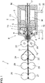
- FIG 1 For a general understanding of the functioning of a spinning device 2, the basic structure of a drafting system 1 with a downstream spinning device 2, which is multi-part in this exemplary embodiment, is shown.
- the sliver 11 withdrawn from a sliver source, not shown here, is drawn in by an input roller pair formed by an input upper roller 26 and an input lower roller 27 .
- the sliver 11 is then drawn between the second upper drafting roller 28 and the second lower drafting roller 29 and the third upper drafting roller 24 and third lower drafting roller 25 and the subsequent output roller pair consisting of upper roller 22 and lower roller 23 warped.
- the drawn fiber sliver 11 then enters the spinning device 2 via an entry area 12 of a nozzle device 6 and is transformed there into a thread 16 using a thread-forming unit 3 and the nozzle device 6 of the spinning device 2 .
- the component of the spinning device 2 that has the entry area 12 forms, together with the nozzle device 6, a first part of the spinning device 2.
- the thread-forming unit 3 forms the second part of the spinning device 2, with the first and second parts facing each other for opening the spinning device 2 for cleaning and maintenance purposes are movably designed and stored.
- the nozzle device 6 has nozzles 7 , 8 which are connected to a compressed air source 10 via lines 9 .
- the air flowing out of the nozzles 7, 8 generates a rotating flow within a vortex chamber 4, with which the drawn sliver 11 being supplied is acted upon.
- the thread-forming unit 3 has a thread-forming element designed as a spinning cone 5 which, in cooperation with the nozzle device 6 , forms the thread 16 which is drawn off from the spinning device 2 via the hollow spinning cone 5 via an outlet opening 17 .
- An expansion space 30 that follows the whirl chamber 4 in the thread withdrawal direction is coupled via a further line 31 to a vacuum air source 32 for removing fiber residues.
- the outer winding fibers 19 are wound around the inner core fibers 18 of the sliver 11 due to the turbulent air flow generated within the spinning device 2 or turbulence chamber 4, thereby ensuring the desired strength of the thread 16.
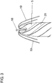
- FIG 2 An embodiment of a spinning device 2 according to a preferred embodiment is shown in the region of the spinning cone 5 and the shell wall 14 of a spinning housing 13 coaxially surrounding the spinning cone 5 .
- the core fiber 18 of the drawn sliver 11 enters a central opening of the hollow spinning cone 5, whereas the outer winding fibers 19 of the sliver 11 reach the enveloping gap 15 due to the air flow circulating around the spinning cone 5 in the region of the enveloping gap 15 between the enveloping wall 14 and the spinning cone 5 .
- opposite electrodes 20 are arranged on the spinning cone 5 and the enveloping wall 14 with the enveloping gap 15 in between, which together form a capacitor unit 21 .
- the electrodes 20 are insulated from the spinning cone 5 or the spinning housing 13, so that after an electric field has been built up between the electrodes 20, the capacitor unit 21 formed from the electrodes 20 experiences a change in capacitance, e.g Enveloping gap 15 learns.
- the electrodes 20 extend opposite one another over the entire peripheral surface of the spinning cone 5 or the casing wall 14 and thus form a capacitor unit 21 in the manner of a ring capacitor.
- the electrodes 20 extend only over a partial area in a spiral shape over the spinning cone 5 and in a corresponding manner on the opposite, not shown here, casing wall 14 of the spinning housing 13.
- the spiral alignment of the electrode 20 corresponds to the alignment of the winding fibers in the spinning operation due to the generated Air flow within the enveloping gap 15.
- This orientation of the electrode 20 thus enables good detection of the winding fibers 19 in the area between the electrodes 20, while at the same time conclusions can be drawn about the rotational speed of the winding fibers 19 around the Spinning cone 5 and measures that can be derived therefrom, such as an adjustment of the spinning process, an adjustment of a delay in the drafting system 1 and/or a stopping of the spinning process and, if necessary, a cleaning of the To tolerance deviations are possible before adjustment of the spinning process or the delay of the thread section produced from the thread.
Landscapes
- Engineering & Computer Science (AREA)
- Mechanical Engineering (AREA)
- Textile Engineering (AREA)
- Physics & Mathematics (AREA)
- General Physics & Mathematics (AREA)
- Spinning Or Twisting Of Yarns (AREA)
Priority Applications (4)
| Application Number | Priority Date | Filing Date | Title |
|---|---|---|---|
| EP20215384.7A EP4015683B1 (fr) | 2020-12-18 | 2020-12-18 | Procédé de surveillance du processus de filage sur un dispositif de filage, poste de filage d'un métier à filer à air ainsi que dispositif de filage |
| CN202111552095.4A CN114645348B (zh) | 2020-12-18 | 2021-12-17 | 监测纺纱过程的方法、气流纺纱机的纺纱位置及纺纱装置 |
| JP2021205373A JP2022097470A (ja) | 2020-12-18 | 2021-12-17 | 紡績装置における紡績過程を監視する方法、空気精紡機の紡績ユニットならびに紡績装置 |
| US17/554,380 US11926934B2 (en) | 2020-12-18 | 2021-12-17 | Method for monitoring the spinning process on a spinning device, spinning position of an air-spinning machine and spinning device |
Applications Claiming Priority (1)
| Application Number | Priority Date | Filing Date | Title |
|---|---|---|---|
| EP20215384.7A EP4015683B1 (fr) | 2020-12-18 | 2020-12-18 | Procédé de surveillance du processus de filage sur un dispositif de filage, poste de filage d'un métier à filer à air ainsi que dispositif de filage |
Publications (2)
| Publication Number | Publication Date |
|---|---|
| EP4015683A1 true EP4015683A1 (fr) | 2022-06-22 |
| EP4015683B1 EP4015683B1 (fr) | 2023-09-13 |
Family
ID=73855735
Family Applications (1)
| Application Number | Title | Priority Date | Filing Date |
|---|---|---|---|
| EP20215384.7A Active EP4015683B1 (fr) | 2020-12-18 | 2020-12-18 | Procédé de surveillance du processus de filage sur un dispositif de filage, poste de filage d'un métier à filer à air ainsi que dispositif de filage |
Country Status (4)
| Country | Link |
|---|---|
| US (1) | US11926934B2 (fr) |
| EP (1) | EP4015683B1 (fr) |
| JP (1) | JP2022097470A (fr) |
| CN (1) | CN114645348B (fr) |
Citations (3)
| Publication number | Priority date | Publication date | Assignee | Title |
|---|---|---|---|---|
| JPH076274U (ja) * | 1993-06-29 | 1995-01-27 | 村田機械株式会社 | 空気紡績装置 |
| DE102007009074A1 (de) | 2007-02-24 | 2008-08-28 | Oerlikon Textile Gmbh & Co. Kg | Spinnvorrichtung |
| EP3040458A1 (fr) * | 2014-11-27 | 2016-07-06 | Murata Machinery, Ltd. | Dispositif et procédé d'alimentation de fil composé d'une âme et machine de filage |
Family Cites Families (4)
| Publication number | Priority date | Publication date | Assignee | Title |
|---|---|---|---|---|
| JP2003155630A (ja) * | 2001-09-05 | 2003-05-30 | Murata Mach Ltd | 紡績装置 |
| JP3925533B2 (ja) * | 2004-11-05 | 2007-06-06 | 村田機械株式会社 | 紡績装置、及び繊維蓄積状態の検出方法 |
| JP2013067882A (ja) * | 2011-09-21 | 2013-04-18 | Murata Mach Ltd | 糸巻取機、及び紡績糸の製造方法 |
| EP3708700A1 (fr) * | 2019-03-13 | 2020-09-16 | Kavitha Chandran | Banc à broches doté d'un système de surveillance |
-
2020
- 2020-12-18 EP EP20215384.7A patent/EP4015683B1/fr active Active
-
2021
- 2021-12-17 US US17/554,380 patent/US11926934B2/en active Active
- 2021-12-17 CN CN202111552095.4A patent/CN114645348B/zh active Active
- 2021-12-17 JP JP2021205373A patent/JP2022097470A/ja not_active Ceased
Patent Citations (3)
| Publication number | Priority date | Publication date | Assignee | Title |
|---|---|---|---|---|
| JPH076274U (ja) * | 1993-06-29 | 1995-01-27 | 村田機械株式会社 | 空気紡績装置 |
| DE102007009074A1 (de) | 2007-02-24 | 2008-08-28 | Oerlikon Textile Gmbh & Co. Kg | Spinnvorrichtung |
| EP3040458A1 (fr) * | 2014-11-27 | 2016-07-06 | Murata Machinery, Ltd. | Dispositif et procédé d'alimentation de fil composé d'une âme et machine de filage |
Also Published As
| Publication number | Publication date |
|---|---|
| EP4015683B1 (fr) | 2023-09-13 |
| CN114645348B (zh) | 2023-09-19 |
| CN114645348A (zh) | 2022-06-21 |
| JP2022097470A (ja) | 2022-06-30 |
| US20220195637A1 (en) | 2022-06-23 |
| US11926934B2 (en) | 2024-03-12 |
Similar Documents
| Publication | Publication Date | Title |
|---|---|---|
| DE2462532C2 (de) | Vorrichtung zum Erkennen des fehlerhaften Arbeitens von Spinnmaschinen | |
| EP2955256B1 (fr) | Metier a filer a jet d'air et procede de fonctionnement d'un tel metier a filer a jet d'air | |
| EP2831319A1 (fr) | Banc à broches présentant un dispositif de détection et d'élimination de défauts de fil | |
| DE19939711B4 (de) | Verfahren und Vorrichtung zur Detektierung von Fremdkörpern in einem längsbewegten Faden | |
| DE4328771C2 (de) | Verfahren und Vorrichtung zur Herstellung eines gesponnenen Fadens | |
| WO2020178779A1 (fr) | Procédé de fabrication de fil au moyen d'un continu à filer à anneaux et continu à filer à anneaux | |
| EP1817448B1 (fr) | Procede pour optimiser le rendement de la production d'un metier a filer | |
| WO2016026734A1 (fr) | Procédé de bobinage d'une pluralité de fils et bobineuse | |
| DE10059967B4 (de) | Verfahren und Anordnung zum Überwachen eines Fadenansetzers an einer Spinnmaschine | |
| DE4492654B4 (de) | Verfahren zur Fehlerdiagnose in einem Herstellungsprozess eines synthetischen Fadens | |
| DE3928022A1 (de) | Verfahren zum umspulen eines fadens mit einer festgelegten laenge in einer doppeldrahtzwirnmaschine | |
| EP4015683B1 (fr) | Procédé de surveillance du processus de filage sur un dispositif de filage, poste de filage d'un métier à filer à air ainsi que dispositif de filage | |
| DE10026389A1 (de) | Vorrichtung zur Überwachung von Garnparametern eines laufenden Fadens | |
| EP1076123B1 (fr) | Procédé et dispositif pour le filage centrifuge | |
| DE102004040214A1 (de) | Textilmaschine und Verfahren zur Ansetzeroptimierung | |
| DE102004013776A1 (de) | Verfahren und Vorrichtung zur Ausreinigung von Garnfehlern | |
| EP1671119B1 (fr) | Procede et dispositif de controle d'un fil | |
| EP3464691B1 (fr) | Élément de formation de fil pour une machine de pré-filage et machine de pré-filage équipée de cet élément | |
| WO1999063139A1 (fr) | Procede mis en oeuvre lors de la production de fil ayant subi un traitement de compacite et dispositif correspondant | |
| DE19649329B4 (de) | Verfahren zum Überprüfen des Fadenprofils an einem laufenden Faden beim Anspinnen in einer Offenend-Spinnmaschine | |
| EP1563128A1 (fr) | Dispositif de filage a chaud et d'enroulement de plusieurs fils | |
| DE2437485A1 (de) | Verfahren und vorrichtung zum ueberwachen der arbeitsweise von faeden liefernden textilmaschinen | |
| EP0024695B1 (fr) | Dispositif de surveillance de la rupture du fil pour fils composés de plusieurs fils | |
| EP0555639A2 (fr) | Procédé pour le réglage de la force de tension des fils en mouvement sur une machine à texturer par fausse torsion | |
| EP3693308A1 (fr) | Tube de stockage de fil pour une poste de travail d'une machine textile ainsi que poste de travail d'une machine textile |
Legal Events
| Date | Code | Title | Description |
|---|---|---|---|
| PUAI | Public reference made under article 153(3) epc to a published international application that has entered the european phase |
Free format text: ORIGINAL CODE: 0009012 |
|
| STAA | Information on the status of an ep patent application or granted ep patent |
Free format text: STATUS: THE APPLICATION HAS BEEN PUBLISHED |
|
| AK | Designated contracting states |
Kind code of ref document: A1 Designated state(s): AL AT BE BG CH CY CZ DE DK EE ES FI FR GB GR HR HU IE IS IT LI LT LU LV MC MK MT NL NO PL PT RO RS SE SI SK SM TR |
|
| STAA | Information on the status of an ep patent application or granted ep patent |
Free format text: STATUS: REQUEST FOR EXAMINATION WAS MADE |
|
| 17P | Request for examination filed |
Effective date: 20221222 |
|
| RBV | Designated contracting states (corrected) |
Designated state(s): AL AT BE BG CH CY CZ DE DK EE ES FI FR GB GR HR HU IE IS IT LI LT LU LV MC MK MT NL NO PL PT RO RS SE SI SK SM TR |
|
| GRAP | Despatch of communication of intention to grant a patent |
Free format text: ORIGINAL CODE: EPIDOSNIGR1 |
|
| STAA | Information on the status of an ep patent application or granted ep patent |
Free format text: STATUS: GRANT OF PATENT IS INTENDED |
|
| RIC1 | Information provided on ipc code assigned before grant |
Ipc: D01H 13/22 20060101ALI20230329BHEP Ipc: D01H 1/115 20060101AFI20230329BHEP |
|
| INTG | Intention to grant announced |
Effective date: 20230428 |
|
| GRAS | Grant fee paid |
Free format text: ORIGINAL CODE: EPIDOSNIGR3 |
|
| GRAA | (expected) grant |
Free format text: ORIGINAL CODE: 0009210 |
|
| STAA | Information on the status of an ep patent application or granted ep patent |
Free format text: STATUS: THE PATENT HAS BEEN GRANTED |
|
| AK | Designated contracting states |
Kind code of ref document: B1 Designated state(s): AL AT BE BG CH CY CZ DE DK EE ES FI FR GB GR HR HU IE IS IT LI LT LU LV MC MK MT NL NO PL PT RO RS SE SI SK SM TR |
|
| REG | Reference to a national code |
Ref country code: CH Ref legal event code: EP |
|
| REG | Reference to a national code |
Ref country code: DE Ref legal event code: R096 Ref document number: 502020005224 Country of ref document: DE |
|
| REG | Reference to a national code |
Ref country code: IE Ref legal event code: FG4D Free format text: LANGUAGE OF EP DOCUMENT: GERMAN |
|
| REG | Reference to a national code |
Ref country code: LT Ref legal event code: MG9D |
|
| REG | Reference to a national code |
Ref country code: NL Ref legal event code: MP Effective date: 20230913 |
|
| PG25 | Lapsed in a contracting state [announced via postgrant information from national office to epo] |
Ref country code: GR Free format text: LAPSE BECAUSE OF FAILURE TO SUBMIT A TRANSLATION OF THE DESCRIPTION OR TO PAY THE FEE WITHIN THE PRESCRIBED TIME-LIMIT Effective date: 20231214 |
|
| PG25 | Lapsed in a contracting state [announced via postgrant information from national office to epo] |
Ref country code: SE Free format text: LAPSE BECAUSE OF FAILURE TO SUBMIT A TRANSLATION OF THE DESCRIPTION OR TO PAY THE FEE WITHIN THE PRESCRIBED TIME-LIMIT Effective date: 20230913 Ref country code: RS Free format text: LAPSE BECAUSE OF FAILURE TO SUBMIT A TRANSLATION OF THE DESCRIPTION OR TO PAY THE FEE WITHIN THE PRESCRIBED TIME-LIMIT Effective date: 20230913 Ref country code: NO Free format text: LAPSE BECAUSE OF FAILURE TO SUBMIT A TRANSLATION OF THE DESCRIPTION OR TO PAY THE FEE WITHIN THE PRESCRIBED TIME-LIMIT Effective date: 20231213 Ref country code: LV Free format text: LAPSE BECAUSE OF FAILURE TO SUBMIT A TRANSLATION OF THE DESCRIPTION OR TO PAY THE FEE WITHIN THE PRESCRIBED TIME-LIMIT Effective date: 20230913 Ref country code: LT Free format text: LAPSE BECAUSE OF FAILURE TO SUBMIT A TRANSLATION OF THE DESCRIPTION OR TO PAY THE FEE WITHIN THE PRESCRIBED TIME-LIMIT Effective date: 20230913 Ref country code: HR Free format text: LAPSE BECAUSE OF FAILURE TO SUBMIT A TRANSLATION OF THE DESCRIPTION OR TO PAY THE FEE WITHIN THE PRESCRIBED TIME-LIMIT Effective date: 20230913 Ref country code: GR Free format text: LAPSE BECAUSE OF FAILURE TO SUBMIT A TRANSLATION OF THE DESCRIPTION OR TO PAY THE FEE WITHIN THE PRESCRIBED TIME-LIMIT Effective date: 20231214 Ref country code: FI Free format text: LAPSE BECAUSE OF FAILURE TO SUBMIT A TRANSLATION OF THE DESCRIPTION OR TO PAY THE FEE WITHIN THE PRESCRIBED TIME-LIMIT Effective date: 20230913 |
|
| PGFP | Annual fee paid to national office [announced via postgrant information from national office to epo] |
Ref country code: TR Payment date: 20231211 Year of fee payment: 4 |
|
| PG25 | Lapsed in a contracting state [announced via postgrant information from national office to epo] |
Ref country code: NL Free format text: LAPSE BECAUSE OF FAILURE TO SUBMIT A TRANSLATION OF THE DESCRIPTION OR TO PAY THE FEE WITHIN THE PRESCRIBED TIME-LIMIT Effective date: 20230913 |
|
| PG25 | Lapsed in a contracting state [announced via postgrant information from national office to epo] |
Ref country code: IS Free format text: LAPSE BECAUSE OF FAILURE TO SUBMIT A TRANSLATION OF THE DESCRIPTION OR TO PAY THE FEE WITHIN THE PRESCRIBED TIME-LIMIT Effective date: 20240113 |
|
| PG25 | Lapsed in a contracting state [announced via postgrant information from national office to epo] |
Ref country code: ES Free format text: LAPSE BECAUSE OF FAILURE TO SUBMIT A TRANSLATION OF THE DESCRIPTION OR TO PAY THE FEE WITHIN THE PRESCRIBED TIME-LIMIT Effective date: 20230913 |
|
| PG25 | Lapsed in a contracting state [announced via postgrant information from national office to epo] |
Ref country code: SM Free format text: LAPSE BECAUSE OF FAILURE TO SUBMIT A TRANSLATION OF THE DESCRIPTION OR TO PAY THE FEE WITHIN THE PRESCRIBED TIME-LIMIT Effective date: 20230913 Ref country code: RO Free format text: LAPSE BECAUSE OF FAILURE TO SUBMIT A TRANSLATION OF THE DESCRIPTION OR TO PAY THE FEE WITHIN THE PRESCRIBED TIME-LIMIT Effective date: 20230913 Ref country code: IS Free format text: LAPSE BECAUSE OF FAILURE TO SUBMIT A TRANSLATION OF THE DESCRIPTION OR TO PAY THE FEE WITHIN THE PRESCRIBED TIME-LIMIT Effective date: 20240113 Ref country code: ES Free format text: LAPSE BECAUSE OF FAILURE TO SUBMIT A TRANSLATION OF THE DESCRIPTION OR TO PAY THE FEE WITHIN THE PRESCRIBED TIME-LIMIT Effective date: 20230913 Ref country code: EE Free format text: LAPSE BECAUSE OF FAILURE TO SUBMIT A TRANSLATION OF THE DESCRIPTION OR TO PAY THE FEE WITHIN THE PRESCRIBED TIME-LIMIT Effective date: 20230913 Ref country code: SK Free format text: LAPSE BECAUSE OF FAILURE TO SUBMIT A TRANSLATION OF THE DESCRIPTION OR TO PAY THE FEE WITHIN THE PRESCRIBED TIME-LIMIT Effective date: 20230913 Ref country code: PT Free format text: LAPSE BECAUSE OF FAILURE TO SUBMIT A TRANSLATION OF THE DESCRIPTION OR TO PAY THE FEE WITHIN THE PRESCRIBED TIME-LIMIT Effective date: 20240115 |
|
| PG25 | Lapsed in a contracting state [announced via postgrant information from national office to epo] |
Ref country code: PL Free format text: LAPSE BECAUSE OF FAILURE TO SUBMIT A TRANSLATION OF THE DESCRIPTION OR TO PAY THE FEE WITHIN THE PRESCRIBED TIME-LIMIT Effective date: 20230913 |
|
| REG | Reference to a national code |
Ref country code: DE Ref legal event code: R097 Ref document number: 502020005224 Country of ref document: DE |
|
| PG25 | Lapsed in a contracting state [announced via postgrant information from national office to epo] |
Ref country code: DK Free format text: LAPSE BECAUSE OF FAILURE TO SUBMIT A TRANSLATION OF THE DESCRIPTION OR TO PAY THE FEE WITHIN THE PRESCRIBED TIME-LIMIT Effective date: 20230913 |
|
| PLBE | No opposition filed within time limit |
Free format text: ORIGINAL CODE: 0009261 |
|
| STAA | Information on the status of an ep patent application or granted ep patent |
Free format text: STATUS: NO OPPOSITION FILED WITHIN TIME LIMIT |
|
| PG25 | Lapsed in a contracting state [announced via postgrant information from national office to epo] |
Ref country code: DK Free format text: LAPSE BECAUSE OF FAILURE TO SUBMIT A TRANSLATION OF THE DESCRIPTION OR TO PAY THE FEE WITHIN THE PRESCRIBED TIME-LIMIT Effective date: 20230913 |
|
| 26N | No opposition filed |
Effective date: 20240614 |
|
| PG25 | Lapsed in a contracting state [announced via postgrant information from national office to epo] |
Ref country code: LU Free format text: LAPSE BECAUSE OF NON-PAYMENT OF DUE FEES Effective date: 20231218 |
|
| PG25 | Lapsed in a contracting state [announced via postgrant information from national office to epo] |
Ref country code: MC Free format text: LAPSE BECAUSE OF FAILURE TO SUBMIT A TRANSLATION OF THE DESCRIPTION OR TO PAY THE FEE WITHIN THE PRESCRIBED TIME-LIMIT Effective date: 20230913 |
|
| REG | Reference to a national code |
Ref country code: BE Ref legal event code: MM Effective date: 20231231 |
|
| PG25 | Lapsed in a contracting state [announced via postgrant information from national office to epo] |
Ref country code: MC Free format text: LAPSE BECAUSE OF FAILURE TO SUBMIT A TRANSLATION OF THE DESCRIPTION OR TO PAY THE FEE WITHIN THE PRESCRIBED TIME-LIMIT Effective date: 20230913 Ref country code: LU Free format text: LAPSE BECAUSE OF NON-PAYMENT OF DUE FEES Effective date: 20231218 |
|
| REG | Reference to a national code |
Ref country code: IE Ref legal event code: MM4A |
|
| PG25 | Lapsed in a contracting state [announced via postgrant information from national office to epo] |
Ref country code: IE Free format text: LAPSE BECAUSE OF NON-PAYMENT OF DUE FEES Effective date: 20231218 |
|
| PG25 | Lapsed in a contracting state [announced via postgrant information from national office to epo] |
Ref country code: BE Free format text: LAPSE BECAUSE OF NON-PAYMENT OF DUE FEES Effective date: 20231231 |
|
| PG25 | Lapsed in a contracting state [announced via postgrant information from national office to epo] |
Ref country code: FR Free format text: LAPSE BECAUSE OF NON-PAYMENT OF DUE FEES Effective date: 20231231 |
|
| PG25 | Lapsed in a contracting state [announced via postgrant information from national office to epo] |
Ref country code: SI Free format text: LAPSE BECAUSE OF FAILURE TO SUBMIT A TRANSLATION OF THE DESCRIPTION OR TO PAY THE FEE WITHIN THE PRESCRIBED TIME-LIMIT Effective date: 20230913 |
|
| PG25 | Lapsed in a contracting state [announced via postgrant information from national office to epo] |
Ref country code: SI Free format text: LAPSE BECAUSE OF FAILURE TO SUBMIT A TRANSLATION OF THE DESCRIPTION OR TO PAY THE FEE WITHIN THE PRESCRIBED TIME-LIMIT Effective date: 20230913 Ref country code: IE Free format text: LAPSE BECAUSE OF NON-PAYMENT OF DUE FEES Effective date: 20231218 Ref country code: FR Free format text: LAPSE BECAUSE OF NON-PAYMENT OF DUE FEES Effective date: 20231231 Ref country code: BE Free format text: LAPSE BECAUSE OF NON-PAYMENT OF DUE FEES Effective date: 20231231 |
|
| PG25 | Lapsed in a contracting state [announced via postgrant information from national office to epo] |
Ref country code: BG Free format text: LAPSE BECAUSE OF FAILURE TO SUBMIT A TRANSLATION OF THE DESCRIPTION OR TO PAY THE FEE WITHIN THE PRESCRIBED TIME-LIMIT Effective date: 20230913 |
|
| PG25 | Lapsed in a contracting state [announced via postgrant information from national office to epo] |
Ref country code: BG Free format text: LAPSE BECAUSE OF FAILURE TO SUBMIT A TRANSLATION OF THE DESCRIPTION OR TO PAY THE FEE WITHIN THE PRESCRIBED TIME-LIMIT Effective date: 20230913 |
|
| PG25 | Lapsed in a contracting state [announced via postgrant information from national office to epo] |
Ref country code: CY Free format text: LAPSE BECAUSE OF FAILURE TO SUBMIT A TRANSLATION OF THE DESCRIPTION OR TO PAY THE FEE WITHIN THE PRESCRIBED TIME-LIMIT; INVALID AB INITIO Effective date: 20201218 |
|
| PG25 | Lapsed in a contracting state [announced via postgrant information from national office to epo] |
Ref country code: HU Free format text: LAPSE BECAUSE OF FAILURE TO SUBMIT A TRANSLATION OF THE DESCRIPTION OR TO PAY THE FEE WITHIN THE PRESCRIBED TIME-LIMIT; INVALID AB INITIO Effective date: 20201218 |
|
| GBPC | Gb: european patent ceased through non-payment of renewal fee |
Effective date: 20241218 |
|
| PG25 | Lapsed in a contracting state [announced via postgrant information from national office to epo] |
Ref country code: GB Free format text: LAPSE BECAUSE OF NON-PAYMENT OF DUE FEES Effective date: 20241218 |
|
| REG | Reference to a national code |
Ref country code: CH Ref legal event code: U11 Free format text: ST27 STATUS EVENT CODE: U-0-0-U10-U11 (AS PROVIDED BY THE NATIONAL OFFICE) Effective date: 20260101 |
|
| PGFP | Annual fee paid to national office [announced via postgrant information from national office to epo] |
Ref country code: AT Payment date: 20260113 Year of fee payment: 5 |
|
| PGFP | Annual fee paid to national office [announced via postgrant information from national office to epo] |
Ref country code: CZ Payment date: 20251205 Year of fee payment: 6 |
|
| PGFP | Annual fee paid to national office [announced via postgrant information from national office to epo] |
Ref country code: DE Payment date: 20251222 Year of fee payment: 6 |
|
| PGFP | Annual fee paid to national office [announced via postgrant information from national office to epo] |
Ref country code: IT Payment date: 20251231 Year of fee payment: 6 |
|
| PGFP | Annual fee paid to national office [announced via postgrant information from national office to epo] |
Ref country code: CH Payment date: 20260101 Year of fee payment: 6 |