EP4015730B1 - Élément composite argile-bois - Google Patents
Élément composite argile-bois Download PDFInfo
- Publication number
- EP4015730B1 EP4015730B1 EP20020618.3A EP20020618A EP4015730B1 EP 4015730 B1 EP4015730 B1 EP 4015730B1 EP 20020618 A EP20020618 A EP 20020618A EP 4015730 B1 EP4015730 B1 EP 4015730B1
- Authority
- EP
- European Patent Office
- Prior art keywords
- clay
- supports
- wood composite
- wooden
- composite element
- Prior art date
- Legal status (The legal status is an assumption and is not a legal conclusion. Google has not performed a legal analysis and makes no representation as to the accuracy of the status listed.)
- Active
Links
Images



Classifications
-
- E—FIXED CONSTRUCTIONS
- E04—BUILDING
- E04C—STRUCTURAL ELEMENTS; BUILDING MATERIALS
- E04C2/00—Building elements of relatively thin form for the construction of parts of buildings, e.g. sheet materials, slabs, or panels
- E04C2/02—Building elements of relatively thin form for the construction of parts of buildings, e.g. sheet materials, slabs, or panels characterised by specified materials
- E04C2/26—Building elements of relatively thin form for the construction of parts of buildings, e.g. sheet materials, slabs, or panels characterised by specified materials composed of materials covered by two or more of groups E04C2/04, E04C2/08, E04C2/10 or of materials covered by one of these groups with a material not specified in one of the groups
-
- E—FIXED CONSTRUCTIONS
- E04—BUILDING
- E04C—STRUCTURAL ELEMENTS; BUILDING MATERIALS
- E04C2/00—Building elements of relatively thin form for the construction of parts of buildings, e.g. sheet materials, slabs, or panels
- E04C2/44—Building elements of relatively thin form for the construction of parts of buildings, e.g. sheet materials, slabs, or panels characterised by the purpose
- E04C2/50—Self-supporting slabs specially adapted for making floors ceilings, or roofs, e.g. able to be loaded
-
- Y—GENERAL TAGGING OF NEW TECHNOLOGICAL DEVELOPMENTS; GENERAL TAGGING OF CROSS-SECTIONAL TECHNOLOGIES SPANNING OVER SEVERAL SECTIONS OF THE IPC; TECHNICAL SUBJECTS COVERED BY FORMER USPC CROSS-REFERENCE ART COLLECTIONS [XRACs] AND DIGESTS
- Y02—TECHNOLOGIES OR APPLICATIONS FOR MITIGATION OR ADAPTATION AGAINST CLIMATE CHANGE
- Y02W—CLIMATE CHANGE MITIGATION TECHNOLOGIES RELATED TO WASTEWATER TREATMENT OR WASTE MANAGEMENT
- Y02W30/00—Technologies for solid waste management
- Y02W30/50—Reuse, recycling or recovery technologies
- Y02W30/91—Use of waste materials as fillers for mortars or concrete
Definitions
- the present invention relates to a method for producing a clay-wood composite element for use as a ceiling element in a building.
- the invention also relates to a clay-wood composite element.
- a clay-wood composite element according to the preamble of claim 8 is described in DE202005011602 U1 described.
- the construction industry is one of the largest consumers of resources in Europe. For example, in Germany around 90% of mineral raw materials are used to build buildings, which is around 517 million tonnes. This means that 52% of German waste is generated by the construction industry.
- the consumption of resources by building structures is a key factor in this. Of great importance here are the primary energy that flows into a structure and is not renewable, the greenhouse potential in CO 2 equivalents and the disposal or recycling of materials.
- Wood, concrete and steel are the main materials used for supporting structures throughout Europe. Wooden supporting structures are generally advantageous from an ecological point of view, but are not ideal in the area of non-renewable energy, because greenhouse gases are also emitted during the processing of wood. Adhesives are also often used for wood composite materials and wood composite elements and wood-based materials, which no longer allow the wood processed with them to biodegrade (for example in composting plants).
- the ceiling construction In a supporting structure, the most material is used for the ceilings. Often, more than 50% of the material consumption for a building is attributable to the ceiling construction. In addition to the primary requirement of the supporting structure to span a room, the ceiling construction usually has to meet a number of other requirements: Requirements of the Fire protection, thermal requirements (heat insulation) and acoustic requirements, for example in terms of sound insulation. In timber construction, these requirements are usually met by additional layers (fire protection layers, fill) and by over-dimensioning (sacrificial layer, which can burn off in the event of a fire). These measures significantly reduce resource efficiency, as more material is used and layers have to be laboriously separated during demolition, which often does not happen.
- Clay-wood composite is an interesting combination of materials for resource-saving ceiling elements.
- the clay could be used as fire protection for the wood and at the same time serve as a thermal and acoustic mass.
- the traditional construction of clay ceilings is based on a primary load-bearing structure made of wooden beams and a secondary load-bearing structure made of boards that are stretched between the wooden beams.
- the secondary load-bearing structure can either be designed as a closed plank floor on which pure clay is stored, or the clay can be stretched over boards as straw clay (so-called staked ceilings), but in both cases the clay only forms a thermal and acoustic mass. It neither solves the fire protection problem, as it relies on a load-bearing layer of wood, which in turn is flammable, nor does it support itself.
- Clay-wood ceilings are therefore of little importance for ceiling constructions in modern construction in Europe, as they do not meet the structural requirements.
- this type of construction is very labor-intensive and can hardly be automated in order to become economically competitive with a concrete ceiling.
- the invention is therefore based on the object of creating clay-wood composite elements for a ceiling system that minimizes primary energy consumption and the emission of CO 2 equivalents, and ensures complete reuse of resources or their biological degradation. Furthermore, the structural requirements for fire protection, building physics (acoustic mass and thermal mass) and economic scalability must be met. In order to ensure the most economical production possible, the degree of automation of production is of the utmost importance.
- the invention provides, according to a first aspect, a method according to claim 1.
- elongated supports are thus placed on a flat surface during the manufacture of the clay-wood composite element for use as a ceiling element in a building and when filling the gaps between the The distance between the supports is maintained so that by compacting the clay in a vertical direction, for example by tamping with a tamping machine or a vibrating plate, compaction is also achieved in a horizontal direction, whereby the clay is placed under compressive stress horizontally between the supports.
- the elongated supports are held at their specified transverse distance by suitable means, the horizontal compressive stress acting in the transverse direction is maintained over the long term, which leads to the clay being self-supporting and the clay being able to absorb vertical loads without the provision of secondary load-bearing structures.
- This meets all the statics requirements of a ceiling element for the construction of ceiling structures in building construction. Due to the self-supporting properties of the clay layer, there is no need for a structure supporting the clay layer from below, so that the clay is in direct contact with the air in the room below in the building, which allows heat and moisture to be exchanged with the room. This fully exploits the excellent thermal and acoustic properties of the clay building material.
- the method according to the invention is easy to handle, so that the clay-wood composite can be produced efficiently and automatically.
- the energy consumption and use of resources are minimal.
- the introduction of the clay and the compaction of the clay can easily be automated, and these steps can be carried out by a robot, for example.
- the proportion of wood in a ceiling construction can be reduced. Since the clay component requires significantly less energy to process than wood, the CO2 emissions and energy consumption of such a ceiling construction are 2 to 5 times lower than those of a purely wooden construction.
- the construction is biodegradable if, as is the preferred design, the elongated supports are made of solid wood. Furthermore, the wood and clay materials can be cleanly separated and reused.
- material transport costs can be reduced by up to 80% if, in the case of clayey soils, excavated material can be used to produce the ceilings and wood can be saved.
- Another great advantage of the method according to the invention and the resulting clay-wood composite element is that the clay protects the wooden structure from the supports burning sideways. In the event of a fire, the clay is fired to form clay, which is even stronger than unfired clay, so that the statics of the building are not affected and the building is less likely to collapse in the event of a fire than with conventional ceiling constructions.
- the clay arranged in the gaps is preferably pure clay, i.e. clay that does not contain any organic or decomposable components, such as straw or wood.
- the clay is introduced into the gap or gaps in a thickness of 5 - 20 cm.
- the transverse distance is maintained by at least one wooden element, such as wooden boards, wooden panels or floorboards, arranged transversely to the elongated supports and fixed to the supports.
- at least one wooden element such as wooden boards, wooden panels or floorboards, arranged transversely to the elongated supports and fixed to the supports.
- the at least one wooden element is preferably arranged on the side of the elongated supports that is directed upwards when installed.
- the method according to the invention can also be carried out in such a way that the distance is maintained by at least one tensioning or pulling element, preferably a tensioning cable or a threaded rod, arranged transversely to the supports and fixed at least to those supports that are arranged on the outermost side.
- at least one tensioning or pulling element preferably a tensioning cable or a threaded rod
- the tensioning or pulling elements absorb the horizontally occurring loads during vertical compaction, whereby the tensioning or pulling elements are preferably only fixed in a tension-resistant manner to the outermost supports and are only guided through any supports that are located between them through holes in the supports.
- This embodiment of the method also allows for subsequent, additional compaction of the clay if the tensioning or pulling elements are tightened after compaction of the clay, as is the case in a preferred embodiment of the present invention.
- the tensioning or pulling elements are secured by turnbuckles, depending on their type.
- Tension nuts and the like are used to tighten the clay between the supports, thereby tensioning it horizontally like prestressed concrete.
- Tests have shown that satisfactory statics of the clay-wood composite elements produced using the method according to the invention are achieved when, according to a preferred embodiment of the present invention, the clay is compacted with a vertical stress of 1 N/mm 2 to 9 N/mm 2 , preferably 3 N/mm 2 to 7 N/mm 2 and a resulting horizontal stress of 0.2 N/mm 2 to 4 N/mm 2 , preferably 1.2 N/mm 2 to 3 N/mm 2 .
- the horizontal stress is measured in the transverse direction, ie transversely, in particular perpendicular to the longitudinal direction of the elongated supports.
- the elongated beams are provided with inclined side surfaces, so that the side surfaces of two adjacent beams facing each other and delimiting the gap converge downwards.
- the resulting clay-wood composite element is installed in a building after the clay has dried or hardened in such a way that the compacted and horizontally braced clay between the beams is additionally supported vertically from below by the inclined side surfaces, as is known in the construction of keystones.
- the elongated beams are provided with strips extending along the side surfaces of the beams delimiting the gap, so that the clay compacted and dried between the beams is additionally supported in the vertical direction.
- a clay-wood composite element according to claim 8 is provided.
- a plurality of carriers is understood here to mean a number of two or more carriers.
- the longitudinal direction is understood to mean the direction of the longitudinal extension of the beams.
- the transverse direction is understood to mean the direction running perpendicular to the longitudinal extension, whereby the longitudinal direction and the transverse direction lie in the ceiling plane when the element is used as the ceiling of a building.
- the transverse direction runs perpendicular to the longitudinal direction according to a preferred embodiment.
- the supports are designed as wooden beams, for example.
- the wooden beams are made of solid wood.
- the compressive stress prevailing in the transverse direction is preferably 0.2 to 4 N/mm 2 .
- the compressive stress can be introduced as explained in connection with the method according to the invention. However, alternative methods for generating the compressive stress are also conceivable.
- holding means are provided which hold the supports at a predetermined transverse distance from each other.
- the holding means can, for example, comprise wooden elements that bridge the gap, such as wooden boards, wooden panels or floorboards, which are rigidly connected to the supports.
- the wooden elements preferably form a continuous surface that extends essentially over the entire longitudinal and transverse extent of the clay-wood composite element.
- the wooden elements preferably form a floor surface for the space of the building arranged above the ceiling.
- the wooden elements can be attached to the supports in a simple manner using pins, nails, screws or clamps and the like.
- the holding means may comprise transversely extending tensioning elements, such as tensioning cables or threaded rods, which engage the supports and the space between
- the tensioning elements preferably run at right angles to the elongated beams, with a plurality of tensioning elements distributed along the length of the beams engaging the beams.
- the tensioning elements can be embedded in the clay or run outside the clay layer.
- a further preferred embodiment provides that the side surfaces of two adjacent supports which face one another and delimit the gap are designed to converge conically downwards or are provided with a strip extending in the longitudinal direction.
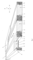
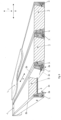
- the clay-wood composite element according to Figure 1 comprises four parallel elongated beams 2 with a rectangular cross-section, which extend in the longitudinal direction 9.
- the two middle beams 2 are composed of two individual beams.
- the beams 2 are arranged next to one another and spaced apart from one another in the transverse direction 8.
- the beams 2 are supported at their ends on a support 1, whereby the support can be designed in addition to its vertical support function to hold the beams 2 at a predetermined transverse distance from one another in the transverse direction. This can be achieved, for example, by positively receiving the beams 2 in recesses in the support 1.
- clay 3 is arranged, which is subject to a compressive stress acting in the transverse direction 8.
- the compressive stress is built up by filling clay 3 into the spaces between the supports 2 when the element is inverted (lying on the floor layer 4) and then compacting the clay 3 by tamping.
- the clay-wood composite element according to Figure 1 Furthermore, in order to secure the transverse distance between the elongated supports 2, it has a tensioning or pulling element 5 in the form of a threaded rod, which can be additionally tensioned by the action of a tension nut 5' after the compaction of the clay 3 in order to tension the clay 3 horizontally, ie in the transverse direction 8.
- the reference numeral 6 designates strips attached to the side surfaces of the supports 2, which extend over the entire length of the supports 2 and provide the clay with additional support in the vertical direction indicated by the double arrow 7.
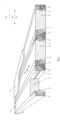
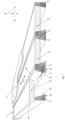
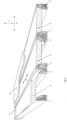
- the clay-wood composite element according to Figure 4 corresponds to that of Figure 3 , however, no tensioning or pulling elements were provided.
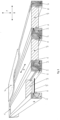
- the clay-wood composite element according to Figure 5 has elongated supports 2, the side surfaces 2c of which laterally delimit the intermediate space are designed to converge conically from a top surface 2b to an opposite bottom surface 2c.
- the clay filling 3 is designed with a curved contour and is compacted, which is considered to be favorable in static terms.
- a tension or tension element 5 is provided.
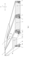
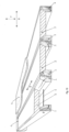
- Figure 9 shows an embodiment of the present invention in which the clay has a reduced layer thickness, wherein the inclined side surfaces of the supports 2 extend only over the layer thickness of the clay 3. In The adjacent side surfaces are formed vertically.
Landscapes
- Engineering & Computer Science (AREA)
- Architecture (AREA)
- Civil Engineering (AREA)
- Structural Engineering (AREA)
- Building Environments (AREA)
- Roof Covering Using Slabs Or Stiff Sheets (AREA)
Claims (14)
- Procédé pour fabriquer un élément composite argile-bois à utiliser comme élément de plafond dans un bâtiment, caractérisé par au moins les étapes suivantes :la fourniture d'une pluralité de supports longitudinaux (2) en bois,la disposition de la pluralité de supports longitudinaux (2) les uns à côté des autres et à une distance transversale les uns des autres sur une surface, dans lequel respectivement un espace intermédiaire est réalisé entre des supports longitudinaux (2) voisins,le remplissage au moins partiel de l'espace intermédiaire ou des espaces intermédiaires avec de l'argile (3), etle compactage de l'argile (3) avec maintien de la distance transversale, en particulier par tassement mécanique de l'argile (3), moyennant quoi l'argile (3) est mise sous contrainte de compression dans la direction transversale (8), dans lequel des moyens de retenue pour retenir les supports (2) à une distance transversale les uns des autres conservant la contrainte de compression sont prévus, de sorte que la couche d'argile, en renonçant à la disposition d'une structure soutenant la couche d'argile par le bas, devient autoporteuse.
- Procédé selon la revendication 1, caractérisé en ce que la distance transversale est maintenue par au moins un élément en bois disposé transversalement par rapport aux supports (2) et fixé sur les supports (2), comme par exemple des planches de bois, panneaux de bois (4) ou lames de plancher.
- Procédé selon la revendication 1, caractérisé en ce que la distance est maintenue par au moins un élément tendeur (5) disposé transversalement par rapport aux supports (2) et fixé au moins sur les supports (2) qui sont disposés le plus à l'extérieur, de préférence un câble tendeur ou une tige filetée.
- Procédé selon la revendication 3, caractérisé en ce que les éléments tendeurs (5) sont tendus après le compactage de l'argile (3).
- Procédé selon l'une quelconque des revendications 1 à 4, caractérisé en ce que le compactage de l'argile (3) s'effectue avec une tension verticale de 1 N/mm2 à 9 N/mm2, de préférence 3 N/mm2 à 7 N/mm2, et une tension horizontale résultante de 0, 2 N/mm2 à 4 N/mm2, de préférence 1 N/mm2 à 3 N/mm2.
- Procédé selon l'une quelconque des revendications 1 à 5, caractérisé en ce que les supports longitudinaux (2) sont fournis avec des surfaces latérales (2c) inclinées, de sorte que les surfaces latérales (2c) de deux supports (3) voisins dirigées l'une vers l'autre, délimitant respectivement l'espace intermédiaire, convergent vers le bas.
- Procédé selon l'une quelconque des revendications 1 à 6, caractérisé en ce que les supports longitudinaux (2) sont fournis avec des baguettes (6) s'étendant le long des surfaces latérales (2c) des supports délimitant l'espace intermédiaire.
- Elément composite argile-bois à utiliser comme élément de plafond dans un bâtiment, comprenant une pluralité de supports longitudinaux (2) en bois s'étendant dans une direction longitudinale (9), qui sont disposés les uns à côté des autres et à distance les uns des autres avec réalisation de respectivement un espace intermédiaire dans une direction transversale (8), et de l'argile (3) remplissant respectivement l'espace intermédiaire entre les supports (2) voisins,
caractérisé en ce que l'argile (3) est mise sous contrainte de compression dans la direction transversale (8) et des moyens de retenue pour retenir les supports (2) à une distance transversale les uns des autres conservant la contrainte de compression sont prévus, de sorte que la couche d'argile est autoporteuse, et dans lequel aucun soutien par le bas par une structure effectuant un soutien par le bas n'est prévu. - Elément composite argile-bois selon la revendication 8, caractérisé en ce que la contrainte de compression atteint 0,2 à 4 N/mm2.
- Elément composite argile-bois selon la revendication 8 ou 9, caractérisé en ce que les supports (2) sont parallèles les uns aux autres.
- Elément composite argile-bois selon la revendication 10, caractérisé en ce que les moyens de retenue comprennent des éléments en bois (1, 4) comblant respectivement l'espace intermédiaire, tels que par exemple des planches de bois, panneaux de bois ou lames de plancher, qui sont reliés fixement aux supports (2).
- Elément composite argile-bois selon la revendication 10 ou 11, caractérisé en ce que les moyens de retenue comprennent des élément tendeurs (5), tels que par exemple des câbles tendeurs ou tiges filetées, qui agissent sur les supports (2) et traversent respectivement l'espace intermédiaire.
- Elément composite argile-bois selon l'une quelconque des revendications 8 à 12, caractérisé en ce que les supports (2) sont constitués de bois massif.
- Elément composite argile-bois selon l'une quelconque des revendications 8 à 13, caractérisé en ce que les surfaces latérales (2c) de deux supports (2) voisins dirigées l'une vers l'autre, délimitant respectivement l'espace intermédiaire, sont réalisées de manière à converger coniquement vers le bas.
Priority Applications (2)
| Application Number | Priority Date | Filing Date | Title |
|---|---|---|---|
| ES20020618T ES3000186T3 (en) | 2020-12-15 | 2020-12-15 | Clay-wood composite element |
| EP20020618.3A EP4015730B1 (fr) | 2020-12-15 | 2020-12-15 | Élément composite argile-bois |
Applications Claiming Priority (1)
| Application Number | Priority Date | Filing Date | Title |
|---|---|---|---|
| EP20020618.3A EP4015730B1 (fr) | 2020-12-15 | 2020-12-15 | Élément composite argile-bois |
Publications (3)
| Publication Number | Publication Date |
|---|---|
| EP4015730A1 EP4015730A1 (fr) | 2022-06-22 |
| EP4015730B1 true EP4015730B1 (fr) | 2024-08-28 |
| EP4015730C0 EP4015730C0 (fr) | 2024-08-28 |
Family
ID=73854517
Family Applications (1)
| Application Number | Title | Priority Date | Filing Date |
|---|---|---|---|
| EP20020618.3A Active EP4015730B1 (fr) | 2020-12-15 | 2020-12-15 | Élément composite argile-bois |
Country Status (2)
| Country | Link |
|---|---|
| EP (1) | EP4015730B1 (fr) |
| ES (1) | ES3000186T3 (fr) |
Families Citing this family (1)
| Publication number | Priority date | Publication date | Assignee | Title |
|---|---|---|---|---|
| EP4502276B1 (fr) | 2023-08-01 | 2026-02-04 | Rematter AG | Procede et dispositif de compactage mecanique de materiaux de sol argileux |
Citations (8)
| Publication number | Priority date | Publication date | Assignee | Title |
|---|---|---|---|---|
| GB369289A (en) | 1929-11-25 | 1932-03-24 | Lorenz Haas | Means for the filling out of wooden frame structures, skeleton buildings of concrete or ferro-concrete, iron structures and the like |
| DE802180C (de) | 1948-10-02 | 1951-02-05 | Walter Rudolph | Formbauplatte |
| DE3627647A1 (de) | 1986-08-14 | 1988-03-03 | Leon Dipl Ing Pytlik | Verfahren zur herstellung von bauteilen mit einer tragenden holzkonstruktion |
| EP0903328A1 (fr) | 1997-08-22 | 1999-03-24 | Roland Meingast | Matériaux de construction en limon ou argile cru |
| DE19950356A1 (de) | 1999-10-19 | 2001-05-23 | Siegfried Burglechner | Mehrschichtige Bauplatte, sowie Verfahren zu ihrer Herstellung |
| DE10338794A1 (de) | 2003-02-07 | 2004-09-02 | Thilo Schneider | Fertigteil für den Lehmbau und Verfahren zur Herstellung desselben |
| EP2060694A1 (fr) | 2007-11-19 | 2009-05-20 | Reinverbund S.R.L. | Elément de paroi de bâtiment |
| AT510797A1 (de) | 2010-12-10 | 2012-06-15 | Thomas Dimov | Bauelement in holzrahmenbauweise aus holz-stegträgern, strohballen und lehm |
Family Cites Families (1)
| Publication number | Priority date | Publication date | Assignee | Title |
|---|---|---|---|---|
| DE202005011602U1 (de) * | 2005-07-23 | 2005-10-20 | Holzbau Kaul Gmbh | Wand-, Decken- und Dachelement für den Hausbau |
-
2020
- 2020-12-15 EP EP20020618.3A patent/EP4015730B1/fr active Active
- 2020-12-15 ES ES20020618T patent/ES3000186T3/es active Active
Patent Citations (8)
| Publication number | Priority date | Publication date | Assignee | Title |
|---|---|---|---|---|
| GB369289A (en) | 1929-11-25 | 1932-03-24 | Lorenz Haas | Means for the filling out of wooden frame structures, skeleton buildings of concrete or ferro-concrete, iron structures and the like |
| DE802180C (de) | 1948-10-02 | 1951-02-05 | Walter Rudolph | Formbauplatte |
| DE3627647A1 (de) | 1986-08-14 | 1988-03-03 | Leon Dipl Ing Pytlik | Verfahren zur herstellung von bauteilen mit einer tragenden holzkonstruktion |
| EP0903328A1 (fr) | 1997-08-22 | 1999-03-24 | Roland Meingast | Matériaux de construction en limon ou argile cru |
| DE19950356A1 (de) | 1999-10-19 | 2001-05-23 | Siegfried Burglechner | Mehrschichtige Bauplatte, sowie Verfahren zu ihrer Herstellung |
| DE10338794A1 (de) | 2003-02-07 | 2004-09-02 | Thilo Schneider | Fertigteil für den Lehmbau und Verfahren zur Herstellung desselben |
| EP2060694A1 (fr) | 2007-11-19 | 2009-05-20 | Reinverbund S.R.L. | Elément de paroi de bâtiment |
| AT510797A1 (de) | 2010-12-10 | 2012-06-15 | Thomas Dimov | Bauelement in holzrahmenbauweise aus holz-stegträgern, strohballen und lehm |
Non-Patent Citations (7)
| Title |
|---|
| ANONYMOUS: "Internationales Benchmark: Systemwahl für die Decken und Anwendungen", EXPERTENFORUM BETON 2005, TAGUNGSBAND, 1 January 2005 (2005-01-01), pages 18 - 25, XP093280857 |
| ANONYMOUS: "Moderner Holzbau Bürogebäude und Forschungslabor", ETH ZÜRICH INSTITUT FÜR BAUSTATIK UND KONSTRUKTION (IBK), 1 January 2016 (2016-01-01), XP093280848, Retrieved from the Internet <URL:https://ethz.ch/content/dam/ethz/special-interest/baug/honr-dam/Flyer_D.pdf> |
| ANONYMOUS: "Regeln zum Bauen mit Lehm", SIA SCHWEIZERISCHER INGENIEUR- UND ARCHITEKTEN-VEREIN, 1 April 1994 (1994-04-01), XP093280861 |
| ANONYMOUS: "Spannend gelöst", SCHREINER ZEITUNG, vol. 45, 10 November 2016 (2016-11-10), XP093280851 |
| ANONYMOUS: "Vorspanntechnik", STAHLTON AG, 1 January 2004 (2004-01-01), XP093280860 |
| DIODATO MARIA, MACCHIONI NICOLA, BRUNETTI MICHELE, PIZZO BENEDETTO, NOCETTI MICHELA, BURATO PAOLO, SOZZI LORENA, PECORARO ELISA, L: "Understanding Spanish Timber Jack Arch Floors: Examples of Assessment and Conservation Issues", INTERNATIONAL JOURNAL OF ARCHITECTURAL HERITAGE, vol. 9, no. 6, 18 August 2015 (2015-08-18), pages 641 - 654, XP093280853, ISSN: 1558-3058, DOI: 10.1080/15583058.2015.1041193 |
| POHLMANN JÜRGEN: "Möglichkeiten der Vorspanntechnik im Ingenieurholzbau – vom Tragwerk zur Decke", 10. INTERNATIONALES HOLZBAU-FORUM 2004, 1 January 2004 (2004-01-01), XP093280844 |
Also Published As
| Publication number | Publication date |
|---|---|
| ES3000186T3 (en) | 2025-02-27 |
| EP4015730A1 (fr) | 2022-06-22 |
| EP4015730C0 (fr) | 2024-08-28 |
Similar Documents
| Publication | Publication Date | Title |
|---|---|---|
| EP2787140B1 (fr) | Plafond plat en structure composite bois-béton et procédé de fabrication d'un tel plafond plat | |
| DE1807716A1 (de) | Vorgefertigtes,transportables Raumelement zur Herstellung von Bauwerken | |
| EP2060694B1 (fr) | Elément de paroi de bâtiment | |
| DE1810434C3 (de) | Hochbauwerk | |
| CH628107A5 (de) | Vorgespanntes deckenfeld, insbesondere zur herstellung von hochbaudecken, sowie verfahren zur herstellung von deckenfeldern. | |
| EP4015730B1 (fr) | Élément composite argile-bois | |
| EP0164330B1 (fr) | Plancher en béton armé | |
| DE2424184A1 (de) | Selbsttragender traeger fuer die schalungsfreie herstellung von decken, insbesondere stahlbetonrippendecken, sowie verfahren zur herstellung derartiger decken, insbesondere stahlbetonrippendecken unter verwendung derartiger selbsttragender traeger | |
| EP2189586A1 (fr) | Elément de plaque doté d'un renforcement | |
| CH674546A5 (en) | Construction of reinforced concrete wall in tunnel - whereby concrete is sprayed over mesh direct on to rock face | |
| DE19801370A1 (de) | Tafelelement | |
| EP4388158A1 (fr) | Éléments sandwich en verre cellulaire et leur utilisation | |
| CH698330B1 (de) | Holz-Beton-Verbundelement und Verfahren zu seiner Herstellung. | |
| DE102011110920B4 (de) | Gebäude sowie Verfahren zu seiner Herstellung | |
| DE3119623A1 (de) | Tragendes, plattenfoermiges bauelement | |
| DE901467C (de) | Zwei- oder mehrschalige, kreuzweis bewehrte Wand, Decke od. dgl. | |
| DE2153495A1 (de) | Fertigteildeckenplatte fuer den montagebau | |
| DE102020206226A1 (de) | Trägerelement und Verfahren zur Herstellung einer freikragenden Balkonanlage sowie Verwendung eines Trägerelements zur Herstellung einer freikragenden Balkonanlage | |
| DE102007063668B4 (de) | Montagebauteil für selbsttragende Dachtafeln oder Wandplatten aus Porenbeton | |
| AT3590U1 (de) | Holzbauelement | |
| DE2729474A1 (de) | Grossflaechiges fertighaus-wandelement in leichtbau-sandwich-ausfuehrung | |
| DE3308156A1 (de) | Bauwerk (gebaeude bzw. ingenieurbauwerk) | |
| AT377302B (de) | Vorgefertigtes bauelement fuer decken, daecher oder waende | |
| DE896860C (de) | In sich vorgespanntes Bewehrungselement aus Formsteinen | |
| DE2436706A1 (de) | Grossflaechige spannbetondecke und verfahren zu deren herstellung |
Legal Events
| Date | Code | Title | Description |
|---|---|---|---|
| PUAI | Public reference made under article 153(3) epc to a published international application that has entered the european phase |
Free format text: ORIGINAL CODE: 0009012 |
|
| STAA | Information on the status of an ep patent application or granted ep patent |
Free format text: STATUS: THE APPLICATION HAS BEEN PUBLISHED |
|
| AK | Designated contracting states |
Kind code of ref document: A1 Designated state(s): AL AT BE BG CH CY CZ DE DK EE ES FI FR GB GR HR HU IE IS IT LI LT LU LV MC MK MT NL NO PL PT RO RS SE SI SK SM TR |
|
| STAA | Information on the status of an ep patent application or granted ep patent |
Free format text: STATUS: REQUEST FOR EXAMINATION WAS MADE |
|
| 17P | Request for examination filed |
Effective date: 20221020 |
|
| RBV | Designated contracting states (corrected) |
Designated state(s): AL AT BE BG CH CY CZ DE DK EE ES FI FR GB GR HR HU IE IS IT LI LT LU LV MC MK MT NL NO PL PT RO RS SE SI SK SM TR |
|
| RAP1 | Party data changed (applicant data changed or rights of an application transferred) |
Owner name: REMATTER AG |
|
| GRAP | Despatch of communication of intention to grant a patent |
Free format text: ORIGINAL CODE: EPIDOSNIGR1 |
|
| STAA | Information on the status of an ep patent application or granted ep patent |
Free format text: STATUS: GRANT OF PATENT IS INTENDED |
|
| RIC1 | Information provided on ipc code assigned before grant |
Ipc: E04C 2/16 20060101ALN20240503BHEP Ipc: E04B 5/02 20060101ALN20240503BHEP Ipc: E04C 2/26 20060101AFI20240503BHEP |
|
| INTG | Intention to grant announced |
Effective date: 20240527 |
|
| RIC1 | Information provided on ipc code assigned before grant |
Ipc: E04C 2/16 20060101ALN20240510BHEP Ipc: E04B 5/02 20060101ALN20240510BHEP Ipc: E04C 2/26 20060101AFI20240510BHEP |
|
| GRAS | Grant fee paid |
Free format text: ORIGINAL CODE: EPIDOSNIGR3 |
|
| GRAA | (expected) grant |
Free format text: ORIGINAL CODE: 0009210 |
|
| STAA | Information on the status of an ep patent application or granted ep patent |
Free format text: STATUS: THE PATENT HAS BEEN GRANTED |
|
| AK | Designated contracting states |
Kind code of ref document: B1 Designated state(s): AL AT BE BG CH CY CZ DE DK EE ES FI FR GB GR HR HU IE IS IT LI LT LU LV MC MK MT NL NO PL PT RO RS SE SI SK SM TR |
|
| REG | Reference to a national code |
Ref country code: CH Ref legal event code: EP |
|
| REG | Reference to a national code |
Ref country code: DE Ref legal event code: R096 Ref document number: 502020008982 Country of ref document: DE |
|
| REG | Reference to a national code |
Ref country code: IE Ref legal event code: FG4D Free format text: LANGUAGE OF EP DOCUMENT: GERMAN |
|
| U01 | Request for unitary effect filed |
Effective date: 20240911 |
|
| REG | Reference to a national code |
Ref country code: CH Ref legal event code: PK Free format text: BERICHTIGUNGEN |
|
| U07 | Unitary effect registered |
Designated state(s): AT BE BG DE DK EE FI FR IT LT LU LV MT NL PT RO SE SI Effective date: 20241002 |
|
| RAP4 | Party data changed (patent owner data changed or rights of a patent transferred) |
Owner name: REMATTER AG |
|
| RIN2 | Information on inventor provided after grant (corrected) |
Inventor name: HUBER, TOBIAS Inventor name: ROS, NICO |
|
| U1H | Name or address of the proprietor changed after the registration of the unitary effect |
Owner name: REMATTER AG; CH |
|
| U20 | Renewal fee for the european patent with unitary effect paid |
Year of fee payment: 5 Effective date: 20241107 |
|
| PG25 | Lapsed in a contracting state [announced via postgrant information from national office to epo] |
Ref country code: GR Free format text: LAPSE BECAUSE OF FAILURE TO SUBMIT A TRANSLATION OF THE DESCRIPTION OR TO PAY THE FEE WITHIN THE PRESCRIBED TIME-LIMIT Effective date: 20241129 Ref country code: PL Free format text: LAPSE BECAUSE OF FAILURE TO SUBMIT A TRANSLATION OF THE DESCRIPTION OR TO PAY THE FEE WITHIN THE PRESCRIBED TIME-LIMIT Effective date: 20240828 |
|
| PG25 | Lapsed in a contracting state [announced via postgrant information from national office to epo] |
Ref country code: IS Free format text: LAPSE BECAUSE OF FAILURE TO SUBMIT A TRANSLATION OF THE DESCRIPTION OR TO PAY THE FEE WITHIN THE PRESCRIBED TIME-LIMIT Effective date: 20241228 |
|
| PG25 | Lapsed in a contracting state [announced via postgrant information from national office to epo] |
Ref country code: HR Free format text: LAPSE BECAUSE OF FAILURE TO SUBMIT A TRANSLATION OF THE DESCRIPTION OR TO PAY THE FEE WITHIN THE PRESCRIBED TIME-LIMIT Effective date: 20240828 |
|
| PG25 | Lapsed in a contracting state [announced via postgrant information from national office to epo] |
Ref country code: RS Free format text: LAPSE BECAUSE OF FAILURE TO SUBMIT A TRANSLATION OF THE DESCRIPTION OR TO PAY THE FEE WITHIN THE PRESCRIBED TIME-LIMIT Effective date: 20241128 |
|
| PG25 | Lapsed in a contracting state [announced via postgrant information from national office to epo] |
Ref country code: RS Free format text: LAPSE BECAUSE OF FAILURE TO SUBMIT A TRANSLATION OF THE DESCRIPTION OR TO PAY THE FEE WITHIN THE PRESCRIBED TIME-LIMIT Effective date: 20241128 Ref country code: PL Free format text: LAPSE BECAUSE OF FAILURE TO SUBMIT A TRANSLATION OF THE DESCRIPTION OR TO PAY THE FEE WITHIN THE PRESCRIBED TIME-LIMIT Effective date: 20240828 Ref country code: IS Free format text: LAPSE BECAUSE OF FAILURE TO SUBMIT A TRANSLATION OF THE DESCRIPTION OR TO PAY THE FEE WITHIN THE PRESCRIBED TIME-LIMIT Effective date: 20241228 Ref country code: HR Free format text: LAPSE BECAUSE OF FAILURE TO SUBMIT A TRANSLATION OF THE DESCRIPTION OR TO PAY THE FEE WITHIN THE PRESCRIBED TIME-LIMIT Effective date: 20240828 Ref country code: GR Free format text: LAPSE BECAUSE OF FAILURE TO SUBMIT A TRANSLATION OF THE DESCRIPTION OR TO PAY THE FEE WITHIN THE PRESCRIBED TIME-LIMIT Effective date: 20241129 |
|
| REG | Reference to a national code |
Ref country code: ES Ref legal event code: FG2A Ref document number: 3000186 Country of ref document: ES Kind code of ref document: T3 Effective date: 20250227 |
|
| PG25 | Lapsed in a contracting state [announced via postgrant information from national office to epo] |
Ref country code: SM Free format text: LAPSE BECAUSE OF FAILURE TO SUBMIT A TRANSLATION OF THE DESCRIPTION OR TO PAY THE FEE WITHIN THE PRESCRIBED TIME-LIMIT Effective date: 20240828 |
|
| PG25 | Lapsed in a contracting state [announced via postgrant information from national office to epo] |
Ref country code: CZ Free format text: LAPSE BECAUSE OF FAILURE TO SUBMIT A TRANSLATION OF THE DESCRIPTION OR TO PAY THE FEE WITHIN THE PRESCRIBED TIME-LIMIT Effective date: 20240828 |
|
| PG25 | Lapsed in a contracting state [announced via postgrant information from national office to epo] |
Ref country code: SK Free format text: LAPSE BECAUSE OF FAILURE TO SUBMIT A TRANSLATION OF THE DESCRIPTION OR TO PAY THE FEE WITHIN THE PRESCRIBED TIME-LIMIT Effective date: 20240828 |
|
| PLBI | Opposition filed |
Free format text: ORIGINAL CODE: 0009260 |
|
| PLAX | Notice of opposition and request to file observation + time limit sent |
Free format text: ORIGINAL CODE: EPIDOSNOBS2 |
|
| 26 | Opposition filed |
Opponent name: LEHMIT GMBH Effective date: 20250519 |
|
| PG25 | Lapsed in a contracting state [announced via postgrant information from national office to epo] |
Ref country code: MC Free format text: LAPSE BECAUSE OF FAILURE TO SUBMIT A TRANSLATION OF THE DESCRIPTION OR TO PAY THE FEE WITHIN THE PRESCRIBED TIME-LIMIT Effective date: 20240828 |
|
| PLBB | Reply of patent proprietor to notice(s) of opposition received |
Free format text: ORIGINAL CODE: EPIDOSNOBS3 |
|
| PG25 | Lapsed in a contracting state [announced via postgrant information from national office to epo] |
Ref country code: IE Free format text: LAPSE BECAUSE OF NON-PAYMENT OF DUE FEES Effective date: 20241215 |
|
| U20 | Renewal fee for the european patent with unitary effect paid |
Year of fee payment: 6 Effective date: 20251104 |
|
| REG | Reference to a national code |
Ref country code: CH Ref legal event code: U11 Free format text: ST27 STATUS EVENT CODE: U-0-0-U10-U11 (AS PROVIDED BY THE NATIONAL OFFICE) Effective date: 20260101 |
|
| PGFP | Annual fee paid to national office [announced via postgrant information from national office to epo] |
Ref country code: GB Payment date: 20251218 Year of fee payment: 6 |
|
| PGFP | Annual fee paid to national office [announced via postgrant information from national office to epo] |
Ref country code: NO Payment date: 20251216 Year of fee payment: 6 |
|
| PGFP | Annual fee paid to national office [announced via postgrant information from national office to epo] |
Ref country code: ES Payment date: 20260119 Year of fee payment: 6 |
|
| PGFP | Annual fee paid to national office [announced via postgrant information from national office to epo] |
Ref country code: CH Payment date: 20260101 Year of fee payment: 6 |