EP4016027A1 - Dispositif de détermination des tensions mécaniques normales dans un composant élastomère, ainsi que capteur de tension normale associé - Google Patents
Dispositif de détermination des tensions mécaniques normales dans un composant élastomère, ainsi que capteur de tension normale associé Download PDFInfo
- Publication number
- EP4016027A1 EP4016027A1 EP21204873.0A EP21204873A EP4016027A1 EP 4016027 A1 EP4016027 A1 EP 4016027A1 EP 21204873 A EP21204873 A EP 21204873A EP 4016027 A1 EP4016027 A1 EP 4016027A1
- Authority
- EP
- European Patent Office
- Prior art keywords
- resonator
- normal
- elastomer component
- mechanical
- normal stresses
- Prior art date
- Legal status (The legal status is an assumption and is not a legal conclusion. Google has not performed a legal analysis and makes no representation as to the accuracy of the status listed.)
- Pending
Links
Images


Classifications
-
- G—PHYSICS
- G01—MEASURING; TESTING
- G01L—MEASURING FORCE, STRESS, TORQUE, WORK, MECHANICAL POWER, MECHANICAL EFFICIENCY, OR FLUID PRESSURE
- G01L1/00—Measuring force or stress, in general
- G01L1/16—Measuring force or stress, in general using properties of piezoelectric devices
- G01L1/162—Measuring force or stress, in general using properties of piezoelectric devices using piezoelectric resonators
-
- G—PHYSICS
- G01—MEASURING; TESTING
- G01L—MEASURING FORCE, STRESS, TORQUE, WORK, MECHANICAL POWER, MECHANICAL EFFICIENCY, OR FLUID PRESSURE
- G01L3/00—Measuring torque, work, mechanical power, or mechanical efficiency, in general
- G01L3/02—Rotary-transmission dynamometers
- G01L3/04—Rotary-transmission dynamometers wherein the torque-transmitting element comprises a torsionally-flexible shaft
- G01L3/10—Rotary-transmission dynamometers wherein the torque-transmitting element comprises a torsionally-flexible shaft involving electric or magnetic means for indicating
- G01L3/106—Rotary-transmission dynamometers wherein the torque-transmitting element comprises a torsionally-flexible shaft involving electric or magnetic means for indicating involving electrostatic means
-
- H—ELECTRICITY
- H01—ELECTRIC ELEMENTS
- H01P—WAVEGUIDES; RESONATORS, LINES, OR OTHER DEVICES OF THE WAVEGUIDE TYPE
- H01P3/00—Waveguides; Transmission lines of the waveguide type
- H01P3/02—Waveguides; Transmission lines of the waveguide type with two longitudinal conductors
- H01P3/08—Microstrips; Strip lines
- H01P3/085—Triplate lines
-
- H—ELECTRICITY
- H01—ELECTRIC ELEMENTS
- H01Q—ANTENNAS, i.e. RADIO AERIALS
- H01Q1/00—Details of, or arrangements associated with, antennas
- H01Q1/12—Supports; Mounting means
- H01Q1/22—Supports; Mounting means by structural association with other equipment or articles
-
- H—ELECTRICITY
- H01—ELECTRIC ELEMENTS
- H01Q—ANTENNAS, i.e. RADIO AERIALS
- H01Q9/00—Electrically-short antennas having dimensions not more than twice the operating wavelength and consisting of conductive active radiating elements
- H01Q9/04—Resonant antennas
- H01Q9/16—Resonant antennas with feed intermediate between the extremities of the antenna, e.g. centre-fed dipole
Definitions
- the transducers In order to measure mechanical normal and shear stresses, the transducers must be integrated into the component in such a way that they can record the force flow to be measured. If this power flow is inhomogeneous, flat sensors are usually required. Elastomer-based pressure measuring foils, which are inserted into the component for each measurement, depict the distribution of the maximum stresses that have occurred by means of color changes. However, this is usually imprecise, cannot be recorded electronically and an unused pressure measuring foil must be installed, removed again and evaluated for each measurement, which makes this type of recording of normal and shear stresses unattractive.
- DES dielectric elastomer sensors
- An object of the present invention is to create a device for the continuous sensory detection of mechanical normal stresses in elastomeric components. This should be able to be implemented as simply, inexpensively, space-savingly, long-livedly, extensively, for large mechanical normal stresses and/or as flexibly as possible.
- the corresponding normal voltage sensor should be able to be operated without an energy source and/or wirelessly. At the very least, an alternative to known devices of this type or normal stress sensors should be created.
- the present invention relates to a device for detecting mechanical normal stresses in an elastomeric component with an elastomeric component with at least one normal stress sensor, wherein the normal stress sensor has at least one resonator whose Natural frequency is dependent on the mechanical normal stresses to be detected, preferably at least essentially linearly, with at least the resonator being embedded in the elastomer component in such a way that mechanical normal stresses acting on the elastomer component can change the natural frequency of the resonator, and with at least one control unit which is designed is to excite the resonator to vibrate at its natural frequency and to detect its vibrations, the control unit also being designed to determine the mechanical normal stresses of the elastomer component from the detected vibrations of the resonator.
- a resonator of a normal stress sensor can be created and embedded in the elastomer component, the mechanical normal stresses of which are to be detected by sensors from the resonator.
- the resonator can be designed so that mechanical normal stresses in the form of compressive forces and/or tensile forces can influence its vibration behavior in such a way that the vibration behavior of the resonator can be characteristic of the acting mechanical normal stresses. If the resonator is now excited to oscillate and the oscillating behavior of the resonator is recorded and evaluated, conclusions can be drawn about the mechanical normal stresses that are present. As a result, mechanical normal stresses that can occur within the elastomer component can be continuously detected by sensors.
- such a resonator can be easily, quickly, precisely positioned and/or robustly integrated or embedded in the elastomeric component, for example by vulcanization or by gluing.
- Such a resonator can also be made available as a simple component at comparatively low cost.
- the resonator is made of elastic materials.
- the resonator can flexibly adapt to the movements of the elastomeric component, which can be caused by the normal mechanical stresses, and can thereby detect the normal mechanical stresses comparatively precisely. Due to its elastic design, the resonator can also follow much stronger expansions than rigid transducers.
- the resonator is designed as a high-frequency resonator.
- a high-frequency resonator is understood to mean a resonator which can work in the frequency range of high-frequency oscillations. This is understood to mean frequencies in the frequency range from 1 to 300 GHz.
- the advantage here is that such high frequencies have correspondingly small wavelengths and the resonator can thus be realized with comparatively small dimensions.
- the comparatively small resonator can also be integrated into very small elastomer components.
- a small resonator may favor being embedded within elastomeric components.
- Another advantage of this is that due to the high frequency, no interaction between the electromagnetic field of the resonator and the elastomer components themselves can occur, which could have a negative effect on the functionality.
- the resonator can be very sensitive to the measured value signal and thus to normal force or pressure. This can increase the measurement sensitivity.
- the resonator has at least one pair of electrically conductive conductor layers perpendicular to the direction of the mechanical normal stresses, between which at least one dielectric is arranged, wherein at least one conductor strip is arranged in the dielectric and extends parallel to the electrically conductive conductor layers .
- the resonator is designed to extend over a surface area, with the resonator being embedded in the elastomer component with its two-dimensional plane of extension perpendicular to the direction of the mechanical normal stresses. This can favor a large-scale sensory detection of the mechanical normal stresses, which can improve the quality of the sensory values.
- the normal voltage sensor has an antenna which is electrically conductively connected to the resonator by means of an electrical connecting element
- the control unit has an antenna for generating an electromagnetic field for electromagnetic coupling to the antenna of the normal voltage sensor.
- control unit is designed to excite the resonator to oscillate at its natural frequency by means of broadband pulses, to record its impulse responses and to determine the mechanical normal stresses from the recorded impulse responses.
- This can represent a way of operating the resonator To stimulate vibrations in its natural frequency and to detect or receive the corresponding signal of the resonator.
- control unit is designed to continuously excite the resonator with oscillations of variable frequency to oscillate at its natural frequency, to detect its oscillations, to determine the transmission parameters from the resonant frequency of the detected oscillations and to determine the mechanical normal stresses from the transmission parameters determined .
- This can represent an alternative mode of operation, exciting the resonator to oscillate at its natural frequency and detecting or receiving the corresponding signal of the resonator.
- the present invention also relates to a normal stress sensor for use in a device for detecting mechanical normal stresses in an elastomer component as described above.
- a normal stress sensor can be created in order to implement the device described above and to be able to use its properties and advantages.
- the present invention also relates to a control unit for use in a device for detecting mechanical normal stresses in an elastomer component as described above.
- a control unit can be created in order to implement the device described above and to be able to use its properties and advantages.
- the control unit can also be used universally, for example for similar devices or measuring systems, with appropriate adaptation of the software implementation of the functions described above to the respective application.
- the normal voltage sensor 1 shows a longitudinal section through a normal voltage sensor 1 according to the invention.
- the normal voltage sensor 1 consists of a resonator 10 which is connected to an antenna 15 via an electrical connecting element 14 in the form of a passive matching circuit 14 which is implemented as a thin conductor foil.
- the resonator 10 is designed as a symmetrical stripline and consists of two electrically conductive conductor layers 11, which accommodate a dielectric 12 between them perpendicularly to their planar extension.
- An electrically conductive conductor strip 13 is embedded in the dielectric 12 in such a way that the two-dimensional extent of the electrically conductive conductor strip 13 extends parallel to the two electrically conductive conductor layers 11 .
- the antenna 15 is designed as a dipole.
- the electrically conductive conductor strip 13 is via the electrical connecting element 14 as a coaxial line (not shown) or via the central conductor of the electrical connecting element 14 with one part of the antenna 15 and the two electrically conductive conductor layers 11 electrically conductively connected via the electrical connecting element 14 or its outer surface to the other part of the antenna 15 as ground.
- a coaxial line as the electrical connection element 14
- a microstrip line can also be used as a space-saving alternative.
- the resonator 10 is thus designed as a symmetrical stripline, a so-called stripline.
- Mechanical normal stresses A can act on the normal stress sensor 1 perpendicularly to the planar extension of the resonator 10 and can be detected by sensors, as will be described in more detail below.
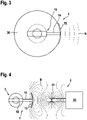
- FIG 2 shows a longitudinal section through an elastomer component 3 according to a first exemplary embodiment with the normal stress sensor 1 according to the invention.
- 3 shows a cross section through the 2 .
- 4 shows a cross section through a device according to the invention for detecting mechanical normal stresses in the elastomer component 3 of FIG 2 .
- the elastomer component 3 has an elastomer element 30 made of rubber, in which the resonator 10 of the normal stress sensor 1 is embedded.
- the electrical connection element 14 of the normal voltage sensor 1 is also embedded in the elastomer element 30 , whereas the antenna 15 is arranged laterally outside of the elastomer element 30 .
- the elastomer element 30 is bonded to a mechanical connection element 31 on both sides along a longitudinal axis X, for example by vulcanization.
- the mechanical connection element 31 is in each case permanently connected to a mechanical connection element 32, by means of which the elastomer component 3 can be connected to other components.
- the device according to the invention also includes a control unit 2 with a transmitter/receiver unit 20 and with an antenna 21.
- the elastomer component 3 is thus equipped with the resonator 10 as a high-frequency resonator 10 whose natural frequency depends on the mechanical normal stress A to be measured.
- the resonator 10 is chosen to be at a frequency in the microwave band, such as 2.45 GHz, for two reasons.
- the resonator 10 can be easily integrated into the elastomer element 30 of the elastomer component 3 due to its small dimensions.
- the antenna 15 of the resonator 10 of the normal voltage sensor 1 is coupled via an electromagnetic field B to the transmitter/receiver unit 20 of the control unit 2 whose antenna 21 is arranged at a small distance from the antenna 15 of the resonator 10 .
- the transmitter/receiver unit 20 excites the resonator 10 to oscillate at its natural frequency and receives the signal from the resonator 10. This can be done at least in that the transmitter/receiver unit 20 excites the resonator 10 with a broadband pulse and the frequency of the impulse response evaluates. Alternatively, this can be done in that the transmitter/receiver unit 20 continuously excites the resonator 10 with a variable frequency (wobble) and determines the resonant frequency from the transmission parameters (S parameters).
- S parameters transmission parameters
- the mechanical normal stresses A compress the resonator 10 to the same extent as the elastomer surrounding the resonator 10.
- the distance between the conductor strip 13 and its outer conductive further conductor layers 11 changes and with it the resonant frequency of the resonator 10. This can be detected and evaluated by the transmitter/receiver unit 20 in order to determine the mechanical normal stresses A.
- the transmitter/receiver unit 20 is designed as a so-called "Software Defined Radio", whose integrated programmable computing unit can implement the above-mentioned modes of operation and determine the measured value signals from the high-frequency signal.
- Striplines are usually constructed from rigid materials.
- the resonator 10 according to the invention consists of elastic materials whose mechanical properties are adapted to the elastomeric environment, so that the resonator 10 can follow the elastic deformations of the elastomeric element 30 of the elastomeric component 3 .
- figure 5 shows a cross section through an elastomer component 3 according to a second exemplary embodiment with the normal stress sensor 1 according to the invention.
- 6 shows a side view of the elastomeric component 3 of FIG figure 5 when used in a clutch 4.
- the normal stress sensor 1 can, for example, in the elastomeric component 3 of Figures 5 and 6 be used in a dog clutch 41 of a clutch 4 to determine the transmitted torque during operation.
- the clutch 4 connects an input shaft 40 along a longitudinal axis X to an output shaft 43 by the teeth 42 of the dog clutch 41 meshing.
- the resonator 10 in at least one tooth 33 and preferably as in the Figures 5 and 6 shown embedded in all teeth 33 of the elastomeric element 30 of the elastomeric component 3 or integrated in such a way that the resonator 10 is exposed to the force flow in the running direction C of the claw clutch 41 .
- the mechanical normal force A or the mechanical Normal stresses A compress the resonator 10 according to the invention.
- Optimum coupling is achieved when the antenna 21 of the transmitter/receiver unit 20 is at the level of the drive shaft 40.
- the electromagnetic field B of the transmitter/receiver unit 20 is additionally modulated by the metallic parts of the claw coupling 41 .
- the current speed of drive shaft 40 can be calculated from this low-frequency modulation.
- the low-frequency modulation has no influence on the evaluation of the high-frequency signal of the resonator 10 by the transmitter/receiver unit 20 .
- a cylindrical structure is also suitable in which the conductor strip 13 runs on the longitudinal axis X of a cylinder whose conductive jacket forms the counter-electrode.
Landscapes
- Physics & Mathematics (AREA)
- General Physics & Mathematics (AREA)
- Measuring Fluid Pressure (AREA)
Applications Claiming Priority (1)
| Application Number | Priority Date | Filing Date | Title |
|---|---|---|---|
| DE102020216234.4A DE102020216234A1 (de) | 2020-12-18 | 2020-12-18 | Vorrichtung zur Erfassung von mechanischen Normalspannungen in einem Elastomerbauteil sowie Normalspannungssensor hierfür |
Publications (1)
| Publication Number | Publication Date |
|---|---|
| EP4016027A1 true EP4016027A1 (fr) | 2022-06-22 |
Family
ID=78413728
Family Applications (1)
| Application Number | Title | Priority Date | Filing Date |
|---|---|---|---|
| EP21204873.0A Pending EP4016027A1 (fr) | 2020-12-18 | 2021-10-26 | Dispositif de détermination des tensions mécaniques normales dans un composant élastomère, ainsi que capteur de tension normale associé |
Country Status (2)
| Country | Link |
|---|---|
| EP (1) | EP4016027A1 (fr) |
| DE (1) | DE102020216234A1 (fr) |
Cited By (2)
| Publication number | Priority date | Publication date | Assignee | Title |
|---|---|---|---|---|
| WO2023274458A1 (fr) * | 2021-06-30 | 2023-01-05 | Contitech Luftfedersysteme Gmbh | Système de capteur de contrainte normale |
| WO2024002435A1 (fr) * | 2022-06-29 | 2024-01-04 | Contitech Deutschland Gmbh | Système de capteur de contrainte normale |
Families Citing this family (4)
| Publication number | Priority date | Publication date | Assignee | Title |
|---|---|---|---|---|
| DE102022120075B4 (de) * | 2022-08-09 | 2024-09-19 | Technische Universität Dresden, Körperschaft des öffentlichen Rechts | Vorrichtung zum messen von betriebsgrössen, insbesondere drehmomenten, in wellenkupplungen mit elastomerbauteilen |
| DE102022210258A1 (de) | 2022-09-28 | 2024-03-28 | Contitech Ag | Drucksensorsystem |
| DE102022210669A1 (de) | 2022-10-10 | 2024-04-11 | Contitech Luftfedersysteme Gmbh | Normalspannungssensorsystem |
| DE102023206087A1 (de) | 2023-06-28 | 2025-01-02 | Contitech Deutschland Gmbh | Normalspannungssensorsystem |
Citations (3)
| Publication number | Priority date | Publication date | Assignee | Title |
|---|---|---|---|---|
| EP2490002A2 (fr) * | 2011-02-15 | 2012-08-22 | Canon Kabushiki Kaisha | Capteur de force de type vibration piézoélectrique et appareil de robot |
| US20130160567A1 (en) * | 2011-12-21 | 2013-06-27 | Canon Kabushiki Kaisha | Force sensor |
| EP2975389A1 (fr) * | 2014-07-17 | 2016-01-20 | ContiTech Luftfedersysteme GmbH | Procede et dispositif de determination non destructive et sans contact de l'etat de vieillissement et/ou de fatigue d'un element contenant de l'elastomere |
-
2020
- 2020-12-18 DE DE102020216234.4A patent/DE102020216234A1/de active Pending
-
2021
- 2021-10-26 EP EP21204873.0A patent/EP4016027A1/fr active Pending
Patent Citations (3)
| Publication number | Priority date | Publication date | Assignee | Title |
|---|---|---|---|---|
| EP2490002A2 (fr) * | 2011-02-15 | 2012-08-22 | Canon Kabushiki Kaisha | Capteur de force de type vibration piézoélectrique et appareil de robot |
| US20130160567A1 (en) * | 2011-12-21 | 2013-06-27 | Canon Kabushiki Kaisha | Force sensor |
| EP2975389A1 (fr) * | 2014-07-17 | 2016-01-20 | ContiTech Luftfedersysteme GmbH | Procede et dispositif de determination non destructive et sans contact de l'etat de vieillissement et/ou de fatigue d'un element contenant de l'elastomere |
Non-Patent Citations (1)
| Title |
|---|
| LI TIEFENG ET AL: "Electromechanical and dynamic analyses of tunable dielectric elastomer resonator", INTERNATIONAL JOURNAL OF SOLIDS AND STRUCTURES, vol. 49, no. 26, 1 December 2012 (2012-12-01), AMSTERDAM, NL, pages 3754 - 3761, XP055908599, ISSN: 0020-7683, Retrieved from the Internet <URL:https://www.sciencedirect.com/science/article/pii/S0020768312003356/pdfft?md5=b8133f5641a8c4bb49d1c3c1e574e977&pid=1-s2.0-S0020768312003356-main.pdf> DOI: 10.1016/j.ijsolstr.2012.08.006 * |
Cited By (2)
| Publication number | Priority date | Publication date | Assignee | Title |
|---|---|---|---|---|
| WO2023274458A1 (fr) * | 2021-06-30 | 2023-01-05 | Contitech Luftfedersysteme Gmbh | Système de capteur de contrainte normale |
| WO2024002435A1 (fr) * | 2022-06-29 | 2024-01-04 | Contitech Deutschland Gmbh | Système de capteur de contrainte normale |
Also Published As
| Publication number | Publication date |
|---|---|
| DE102020216234A1 (de) | 2022-06-23 |
Similar Documents
| Publication | Publication Date | Title |
|---|---|---|
| DE102020216234A1 (de) | Vorrichtung zur Erfassung von mechanischen Normalspannungen in einem Elastomerbauteil sowie Normalspannungssensor hierfür | |
| WO2023274458A1 (fr) | Système de capteur de contrainte normale | |
| DE10236051B4 (de) | Spannungs-/Dehnungsmesssensor sowie Verfahren zur Spannungs-/Dehnungsmessung | |
| EP2828681A1 (fr) | Capteur d'ultrasons et procédé de mesure de la distance d'un objet | |
| WO2024002435A1 (fr) | Système de capteur de contrainte normale | |
| DE10137679C1 (de) | Verfahren und Vorrichtung zur Ermittlung akustischer Parameter von Flüssigkeiten | |
| DE19616859A1 (de) | Mikrowellentelemetrie zum Erfassen von Eigenschaften in einer geschlossenen, drehenden und/oder hin- und herbewegenden Maschine | |
| DE102016012564A1 (de) | Verbindungselement mit integriertem Sensor | |
| DE602004004778T2 (de) | Sensorbaugruppe, fluidpumpe und kühler | |
| EP1891404B1 (fr) | Systeme de mesure de vibration | |
| WO2001067058A1 (fr) | Procede et dispositif permettant de mesurer un moment s'appliquant a un composant | |
| EP4015985A1 (fr) | Dispositif de détermination des dilatations mécaniques dans ou sur un composant élastomère, ainsi que capteur de dilatation associé | |
| EP4016022A1 (fr) | Dispositif de détermination des températures dans ou sur un composant élastomère | |
| DE102015217741A1 (de) | Akustischer Sensor zum Aussenden und Empfangen von akustischen Signalen und Verfahren zum Herstellen eines solchen Sensors | |
| DE102022210669A1 (de) | Normalspannungssensorsystem | |
| DE102016125822A1 (de) | Vibrationssensor | |
| WO2022122490A1 (fr) | Système de capteur ultrasonore pour un véhicule à moteur et procédé de fonctionnement du système de capteur ultrasonore | |
| DE102004018506A1 (de) | Verfahren und Vorrichtung zur Herstellung einer Messvorrichtung zur Bestimmung und/oder Überwachung einer Prozessgröße und entsprechende Messvorrichtung | |
| EP4345435B1 (fr) | Système de capteur de pression | |
| EP3885728A1 (fr) | Système de détection de la dilatation d'un produit élastomère | |
| DE102022109187A1 (de) | Schraubverbindung | |
| DE102023206087A1 (de) | Normalspannungssensorsystem | |
| WO2007045664A1 (fr) | Systeme de mesure de vibration | |
| AT503558A4 (de) | Vorrichtung zur messung von druck, kraft, beschleunigung oder davon abgeleiteten grössen | |
| DE102004060903A1 (de) | Vorrichtung zur Erfassung von physikalischen Eigenschaften eines Gases oder eines Gasgemisches mittels eines Hochfrequenz-Resonators |
Legal Events
| Date | Code | Title | Description |
|---|---|---|---|
| PUAI | Public reference made under article 153(3) epc to a published international application that has entered the european phase |
Free format text: ORIGINAL CODE: 0009012 |
|
| STAA | Information on the status of an ep patent application or granted ep patent |
Free format text: STATUS: THE APPLICATION HAS BEEN PUBLISHED |
|
| AK | Designated contracting states |
Kind code of ref document: A1 Designated state(s): AL AT BE BG CH CY CZ DE DK EE ES FI FR GB GR HR HU IE IS IT LI LT LU LV MC MK MT NL NO PL PT RO RS SE SI SK SM TR |
|
| STAA | Information on the status of an ep patent application or granted ep patent |
Free format text: STATUS: REQUEST FOR EXAMINATION WAS MADE |
|
| 17P | Request for examination filed |
Effective date: 20221222 |
|
| RBV | Designated contracting states (corrected) |
Designated state(s): AL AT BE BG CH CY CZ DE DK EE ES FI FR GB GR HR HU IE IS IT LI LT LU LV MC MK MT NL NO PL PT RO RS SE SI SK SM TR |
|
| STAA | Information on the status of an ep patent application or granted ep patent |
Free format text: STATUS: EXAMINATION IS IN PROGRESS |
|
| 17Q | First examination report despatched |
Effective date: 20241008 |
|
| RAP1 | Party data changed (applicant data changed or rights of an application transferred) |
Owner name: CONTITECH DEUTSCHLAND GMBH |