EP4016060A1 - Messvorrichtung für optische konstante, verfahren zur messung der optischen konstante und verfahren zur berechnung der optischen konstante - Google Patents
Messvorrichtung für optische konstante, verfahren zur messung der optischen konstante und verfahren zur berechnung der optischen konstante Download PDFInfo
- Publication number
- EP4016060A1 EP4016060A1 EP20851707.8A EP20851707A EP4016060A1 EP 4016060 A1 EP4016060 A1 EP 4016060A1 EP 20851707 A EP20851707 A EP 20851707A EP 4016060 A1 EP4016060 A1 EP 4016060A1
- Authority
- EP
- European Patent Office
- Prior art keywords
- double slit
- state
- coherent light
- interference image
- optical constant
- Prior art date
- Legal status (The legal status is an assumption and is not a legal conclusion. Google has not performed a legal analysis and makes no representation as to the accuracy of the status listed.)
- Granted
Links
Images


Classifications
-
- G—PHYSICS
- G01—MEASURING; TESTING
- G01N—INVESTIGATING OR ANALYSING MATERIALS BY DETERMINING THEIR CHEMICAL OR PHYSICAL PROPERTIES
- G01N21/00—Investigating or analysing materials by the use of optical means, i.e. using sub-millimetre waves, infrared, visible or ultraviolet light
- G01N21/17—Systems in which incident light is modified in accordance with the properties of the material investigated
- G01N21/41—Refractivity; Phase-affecting properties, e.g. optical path length
- G01N21/45—Refractivity; Phase-affecting properties, e.g. optical path length using interferometric methods; using Schlieren methods
-
- G—PHYSICS
- G01—MEASURING; TESTING
- G01J—MEASUREMENT OF INTENSITY, VELOCITY, SPECTRAL CONTENT, POLARISATION, PHASE OR PULSE CHARACTERISTICS OF INFRARED, VISIBLE OR ULTRAVIOLET LIGHT; COLORIMETRY; RADIATION PYROMETRY
- G01J3/00—Spectrometry; Spectrophotometry; Monochromators; Measuring colours
- G01J3/02—Details
- G01J3/0205—Optical elements not provided otherwise, e.g. optical manifolds, diffusers, windows
- G01J3/0229—Optical elements not provided otherwise, e.g. optical manifolds, diffusers, windows using masks, aperture plates, spatial light modulators or spatial filters, e.g. reflective filters
-
- G—PHYSICS
- G01—MEASURING; TESTING
- G01J—MEASUREMENT OF INTENSITY, VELOCITY, SPECTRAL CONTENT, POLARISATION, PHASE OR PULSE CHARACTERISTICS OF INFRARED, VISIBLE OR ULTRAVIOLET LIGHT; COLORIMETRY; RADIATION PYROMETRY
- G01J3/00—Spectrometry; Spectrophotometry; Monochromators; Measuring colours
- G01J3/02—Details
- G01J3/10—Arrangements of light sources specially adapted for spectrometry or colorimetry
-
- G—PHYSICS
- G01—MEASURING; TESTING
- G01J—MEASUREMENT OF INTENSITY, VELOCITY, SPECTRAL CONTENT, POLARISATION, PHASE OR PULSE CHARACTERISTICS OF INFRARED, VISIBLE OR ULTRAVIOLET LIGHT; COLORIMETRY; RADIATION PYROMETRY
- G01J3/00—Spectrometry; Spectrophotometry; Monochromators; Measuring colours
- G01J3/12—Generating the spectrum; Monochromators
- G01J3/18—Generating the spectrum; Monochromators using diffraction elements, e.g. grating
-
- G—PHYSICS
- G01—MEASURING; TESTING
- G01J—MEASUREMENT OF INTENSITY, VELOCITY, SPECTRAL CONTENT, POLARISATION, PHASE OR PULSE CHARACTERISTICS OF INFRARED, VISIBLE OR ULTRAVIOLET LIGHT; COLORIMETRY; RADIATION PYROMETRY
- G01J3/00—Spectrometry; Spectrophotometry; Monochromators; Measuring colours
- G01J3/28—Investigating the spectrum
- G01J3/2823—Imaging spectrometer
-
- G—PHYSICS
- G01—MEASURING; TESTING
- G01J—MEASUREMENT OF INTENSITY, VELOCITY, SPECTRAL CONTENT, POLARISATION, PHASE OR PULSE CHARACTERISTICS OF INFRARED, VISIBLE OR ULTRAVIOLET LIGHT; COLORIMETRY; RADIATION PYROMETRY
- G01J3/00—Spectrometry; Spectrophotometry; Monochromators; Measuring colours
- G01J3/28—Investigating the spectrum
- G01J3/45—Interferometric spectrometry
-
- G—PHYSICS
- G01—MEASURING; TESTING
- G01J—MEASUREMENT OF INTENSITY, VELOCITY, SPECTRAL CONTENT, POLARISATION, PHASE OR PULSE CHARACTERISTICS OF INFRARED, VISIBLE OR ULTRAVIOLET LIGHT; COLORIMETRY; RADIATION PYROMETRY
- G01J3/00—Spectrometry; Spectrophotometry; Monochromators; Measuring colours
- G01J3/02—Details
- G01J3/0264—Electrical interface; User interface
Definitions
- the present invention relates to a measurement technique for an optical constant such as a complex refractive index.
- a new measurement method using double-slit interference has been proposed. With this method, the relative intensities of the two optical paths and the phase difference that occurs due to the optical path difference are acquired based on a double-slit interference image obtained using coherent light. This allows a complex refractive index to be directly acquired.
- this light source With an interference measurement using high-order harmonics, which are a source of coherent light, this enables interference measurement without a problem that occurs in the method employing an incoherent light source described above.
- This light source has high coherence and a wide bandwidth. Accordingly, it can be said that this light source is an ideal light source for refractive index measurement and dispersion measurement in refractive index measurement.
- the present disclosure has been made in view of such a situation. Accordingly, it is an exemplary purpose of the present disclosure to provide improved precision of the measurement of optical constants.
- An optical constant measurement apparatus includes: a coherent light source, a spectrometer, a first double slit, a second double slit, and a calculation processing device.
- the coherent light source is structured to output coherent light including high-order harmonics obtained by irradiating short-pulse laser light to a nonlinear medium.
- the spectrometer includes a grating structured to diffract the coherent light and an image sensor structured to acquire an image of light diffracted by the grating.
- the first double slit has a pair of apertures arranged with an interval in a first direction. The first double slit is arranged at a predetermined position between the coherent light source and an incident slit of the spectrometer in a first state.
- the second double slit has a pair of apertures that are a replica of the first double slit.
- the second double slit is arranged at the predetermined position as a replacement of the first double slit in a state in which one from among the pair of apertures holds a sample in a second state.
- the calculation processing device is structured to calculate optical constants of the sample based on a first interference image formed on the image sensor due to the harmonics of the coherent light in the first state and a second interference image formed on the image sensor due to the harmonics in the second state.
- this provides a harmonic-based interferometer with improved accuracy as compared with conventional techniques. Specifically, this provides accuracy that is equal to or higher than that of synchrotron-radiation-based interferometers.
- An optical constant measurement apparatus includes: a coherent light source configured to output coherent light including high-order harmonics obtained by irradiating short-pulse laser light to a nonlinear medium; a spectrometer including a grating configured to diffract the coherent light and an image sensor configured to acquire an image of light diffracted by the grating; a first double slit having a pair of apertures arranged with an interval in a first direction, which are arranged at a predetermined position between the coherent light source and an incident slit of the spectrometer in a first state; a second double slit having a pair of apertures that are a replica of the first double slit, which are arranged at the predetermined position as a replacement of the first double slit in a state in which one from among the pair of apertures holds a sample in a second state; and a calculation processing device configured to calculate optical constants of the sample based on a first interference image formed on the image sensor due to the harmonics of the coherent light
- an interference image is measured using the double slit without a sample.
- an interference image is measured using the double slit with a sample.
- the "optical constant” is the refractive index. More specifically, the “optical constant” is the complex refractive index. However, the “optical constant” is not restricted to the refractive index. Also, examples of the "optical constant” include: a thickness of a material having a known refractive index; a transmittance of a non-transparent material; etc.
- the optical constant measurement apparatus may be modeled using parameters.
- the interference image of the double slit can be modeled based on a model of the optical constant measurement apparatus.
- the parameters of the model are optimized such that the model of the interference image matches the measured interference image. This allows the optical constant of the sample and the parameters including the error of the optical measurement apparatus to be acquired in a quantitative manner.
- the calculation processing device may calculate an intensity distribution formed on the image sensor for each of the first state and the second state using a one-dimensional Fresnel diffraction expression based on the model of the optical constant measurement apparatus. Also, the parameters of the model and the optical constants of the sample may be acquired such that the intensity distributions thus calculated approach the first interference image and the second interference image.
- the optical constant may be quantitatively estimated as a parameter of the model function.
- the statistical uncertainty of the measurement value may be quantified by measurement so as to optimize the design of the double slit such that the uncertainty of the optical constant is minimized.
- the apertures of the first double slit and the second double slit may be modeled using an error function. This is capable of removing the high-frequency components that are equal to or higher than the Nyquist frequency as compared with an arrangement in which the aperture is modeled by a step function.
- the first interference image and the second interference image may each be acquired as an integrated interference image using multiple irradiations of the coherent light. Also, a function of a wavefront of an incident wave to each of the first double slit and the second double slit may be handled assuming that a center position thereof fluctuates in a normal distribution.
- the first double slit and the second double slit may be continuously formed in a second direction that is orthogonal to the first direction.
- the optical constant measurement apparatus may include a stage configured to shift the first double slit and the second double slit in the second direction.
- the coherent light source may include an optical parametric amplifier.
- the coherent light source may be configured to provide the short-pulse laser light with a variable wavelength.
- the coherent light source may include: a main light source configured to generate the short-pulse laser light; a gas nozzle configured to inject a gas that is the nonlinear medium; a focusing optical system configured to focus the short-pulse laser light onto the gas; and a stabilizing apparatus configured to monitor position of the short-pulse laser light at two points in the focusing optical system, wherein the short-pulse laser light is provided as parallel light in one of the two points, and another of the two points is a focusing point of the focusing optical system, so as to control a mechanical state of an optical element of the focusing optical system.
- This allows beam pointing to be stabilized, thereby allowing the uncertainty in the measurement system to be reduced.
- An embodiment of the present disclosure relates to a refractive index measurement method.
- the refractive index measurement method includes: irradiating short-pulse laser light to a nonlinear medium so as to generate coherent light including high-order harmonics; irradiating the coherent light such that it passes through a first double slit having a pair of apertures arranged with an interval in a first direction, so as to measure a first interference image; irradiating the coherent light such that it passes through a second double slit having a pair of apertures that are a replica of the first double slit in a state in which one from among the pair of apertures holds a sample; and calculating an optical constant of the sample based on the first interference image and the second interference image.
- An embodiment of the present disclosure relates to a method for calculating an optical constant.
- This method is a method for calculating an optical constant of a sample based on a first interference image and a second interference image obtained by a measurement system.
- the measurement system includes: a coherent light source configured to output coherent light including high-order harmonics obtained by irradiating short-pulse laser light to a nonlinear medium; a spectrometer including a grating configured to diffract the coherent light and an image sensor configured to acquire an image of light diffracted by the grating; a first double slit having a pair of apertures arranged with an interval in a first direction, which are arranged at a predetermined position between the coherent light source and an incident slit of the spectrometer in a first state; and a second double slit having a pair of apertures that are a replica of the first double slit, which are arranged at the predetermined position as a replacement of the first double slit in a state in
- the first interference image is formed on the image sensor as an image of harmonics of the coherent light.
- the second interference image is formed on the image sensor as an image of the harmonics.
- the calculation method includes: defining a model of the measurement system for each of the first state and the second state; calculating a first diffraction pattern generated by a model of the measurement system in the first state based on a one-dimensional Fresnel diffraction expression; calculating a second diffraction pattern generated by a model of the measurement system in the second state based on a one-dimensional Fresnel diffraction expression; and calculating a parameter of the model of the measurement system and the optical constant of the sample such that the first diffraction pattern approaches the first interference image and the second diffraction pattern approaches the second interference image.
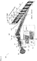
- Fig. 1 is a diagram for explaining the principle of complex refractive index measurement using the double-slit method.
- the shape of a double-slit interference image is analyzed so as to estimate the optical path difference and the intensity ratio between electric fields that have passed through two slits (a double slit) (Non-patent document 8).
- a sample sample 2
- the optical path difference and the intensity ratio between the electric fields are determined by the refractive index and the thickness of the sample.
- the complex refractive index of the sample can be directly acquired by the following Expression (1) based on the two parameters thus estimated, i.e., the phase shift ⁇ and the electric field intensity ratio thus estimated.
- d the thickness of the sample 2
- ⁇ the wavelength.
- the complex refractive index is calculated based on another analysis method as described later.
- Fig. 2 is a diagram showing an optical constant measurement apparatus 100 according to an embodiment.
- the optical constant measurement apparatus 100 provides measurements in two states, i.e., a first state ⁇ 1 and a second state ⁇ 2.
- the optical constant measurement apparatus 100 mainly includes a coherent light source 110, a spectrometer 130, a first double slit 150, a second double slit 152, and a calculation processing device 200.
- the light source is configured as a laser-based high-order harmonic light source, thereby providing a light source with high spatial coherence.
- the coherent light source 110 irradiates short-pulse laser light S0 to a nonlinear medium so as to generate and output coherent light S1 including high-order harmonics.
- a suitable element that provides high-order harmonics with high luminance at a wavelength to be used for the measurement of the complex refractive index may preferably be selected.
- an element may be selected from among rare-gas elements (He, Ne, Ar, Kr, Xe).
- Fig. 3 is a diagram showing a spectrum generated in high-order harmonic generation (HHG).
- the high-order harmonics have peaks at energy values obtained by multiplying the energy of the fundamental wave by an odd number and has a region in which the peaks have uniform intensities regardless of the order over a wide bandwidth (which is referred to as a "plateau region").
- a wide bandwidth which is referred to as a "plateau region”
- interference light is diffracted by a grating, and the diffracted light is focused on an image sensor (e.g., a two-dimensional CCD camera), so as to perform spectroscopic measurement of the interference image.
- the fundamental wave has a variable wavelength. This enables refractive index measurement at a desired wavelength in the EUV region.
- the spectrometer 130 includes a grating 132, an image sensor 134, an incident slit 136, a filter 138, and so forth.
- the grating 132 diffracts the coherent light S1.
- the image sensor 134 captures an image of the light diffracted by the grating 132.
- the filter 138 removes the fundamental wave component from the light that has passed through the incident slit 136, and passes through the harmonic components.
- an aluminum thin film (aluminum filter) or the like may be employed as the filter 138.
- the first double slit 150 has a pair of slits (aperture pair) arranged with an interval in a first direction (vertical direction Y in the drawing). In the first state ⁇ 1, the first double slit 150 is positioned at a predetermined position between the coherent light source 110 and the incident slit 136 of the spectrometer 130.
- the first double slit 150 acts on the harmonics of the coherent light S1, thereby forming a first interference image 300 on the image sensor 134.
- the interference image is formed for each order of the harmonics.
- the second double slit 152 has an aperture pair that is a replica of the first double slit 150 such that they have the same shape and the same size.
- the second double slit 152 is positioned at a predetermined position as a replacement of the first double slit 150 and the second double slit 152 hold the sample 2 at one aperture of its aperture pair.
- the second double slit 152 holding the sample 2 acts on the harmonics of the coherent light S1, thereby forming a second interference image 302 on the image sensor 134.
- the first double slit 150 and the second double slit 152 are continuously formed in the second direction X that is orthogonal to the first direction in the form of a single unit, which will be referred to as a sample holder 160.
- a sample holder 160 With such an arrangement in which the first double slit 150 and the second double slit 152 are formed in the form of a single unit, this is capable of reducing aperture position deviation between the first state ⁇ 1 and the second state ⁇ 2.
- such an arrangement enables positioning of the sample holder 160 in the second direction X by means of a movable stage 170.
- the calculation processing apparatus 200 calculates the complex refractive index of the sample 2 based on the first interference image 300 measured in the first state and the second interference image 302 measured in the second state.
- the optical constant measurement apparatus 100 is represented by a model using parameters.
- the parameters may include variables (unknown values) and constants (known values).
- a parameter that is a large source of error may be defined as a variable.
- a parameter that is a negligible source of error may be defined as a constant.
- the calculation processing device 200 calculates the intensity distribution of the interference image formed on the image sensor 134 in the first state and the second state based on the model of the optical constant measurement apparatus 100 using the one-dimensional Fresnel diffraction expression.
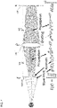
- Fig. 4 is a diagram for explaining the formation of the interference image based on the one-dimensional Fresnel diffraction model.
- I(x) represents the intensity distribution on the sensor surface of the image sensor 134 that functions as a screen.
- the optical constant measurement apparatus 100 is modeled with (i) the wavefront of the coherent light incident to the double slit, (ii) the double slits 150 and 152, (iii) a free space 180 between the double slits 150 and 152 and the grating 132, (iv) the grating 132, and (v) a free space 182 between the grating 132 and the image sensor 134 as the modeling components.
- the free spaces 180 and 182 can be treated as typical propagation in a free space.
- ⁇ is an independent variable that represents the position in the double slit in the vertical direction.
- ⁇ is an independent variable that represents the position in the grating in the vertical direction.
- x is an independent variable that represents the position on the sensor plane of the image sensor.
- the complex refractive index of the sample 2 can be represented in the form of being included in the double-slit model f( ⁇ ). Specifically, the model f( ⁇ ) in the first state ⁇ 1 is independent of the sample 2. In contrast, the model f( ⁇ ) in the second state ⁇ 2 includes the complex refractive index of the sample 2.
- the calculation processing device 200 acquires the model parameters and the complex refractive index of the sample 2 such that the intensity distribution of the interference image calculated based on the model in the first state ⁇ 1 approaches the first interference image 300 and the interference image calculated based on the model in the second state ⁇ 2 approaches the second interference image 302.
- the above is the configuration of the optical constant measurement apparatus 100.
- Fig. 5 is a diagram showing the optical constant measurement apparatus 100 used in the experiments.
- the coherent light source 110 is configured including a main light source 112 and an optical parametric amplifier 114.
- the main light source 112 the Legend Elite Duo (5 kHz, 2.2 mJ), which is a regenerative-amplifier mode-locked Ti:sapphire laser manufactured by Coherent, Inc. was employed.
- the optical parametric amplifier 114 TOPAS-Prime with NirUVis manufactured by LIGHT CONVERSION was employed.
- the second-order harmonic of signal light extracted from the optical parametric amplifier 114 was employed as short-pulse laser light S0 that is the fundamental wave in the high-order harmonics generation.
- the short-pulse laser light S0 thirteen wavelengths ranging from 650 nm to 670 nm can be used.
- the short-pulse laser light S0 has a pulse width of 25 fs, which was measured by means of an FC spider.
- a focusing optical system 116 is configured between the coherent light source 110 and the nonlinear medium 4.
- the fundamental wave having a diameter of 25 mm is focused by means of the focusing optical system 116 on the neon gas injected from a gas nozzle 104 having a diameter of 200 ⁇ m and arranged in a vacuum chamber 102.
- the estimated focusing size of the fundamental wave is approximately 8 ⁇ m.
- the high-order harmonics generated in the neon gas propagate in the same axial direction as in the fundamental wave, and reach the double slit 150 or 152.
- the high-order harmonics which are irradiated to the double slit 150 or 152, have sufficiently high coherence. Accordingly, the wavefront that passes through the double slit 150 or 152 propagates in the same axial direction as in the pointing vector of the incident wavefront with interference in the X 0 direction (vertical direction) shown in Fig. 2 .
- a toroidal grating was employed as the grating 132.
- the harmonics that pass through the incident slit 136 of the spectrometer 130 reach the toroidal grating, and are diffracted in the X-axis direction of the CCD camera shown in Fig. 2 .
- the toroidal grating is arranged such that the interference image that occurs at the incident slit 136 of the spectrometer 130 is dispersed and focused on the CCD camera for each order by means of the toroidal grating.
- the Andor DO940P BN was employed.
- the HORIBA Jobin Yvon 541 00 200 was employed as the toroidal grating.
- the wavelength was calibrated using the McPherson Model 629.
- the sample holder 160 including the double slits 150 and 152 can be moved by means of the movable stage 170. This enables switching between the double slit (first double slit 150) in which both apertures are empty and the double slit (second double slit 152) in which the sample 2 is mounted in one aperture.
- the sample is an aluminum thin film, which was purchased from Luxel.
- the sample has a film thickness of 156 ⁇ 5 nm.
- the refractive index of the sample is measured as an effective refractive index.
- the oxide film was removed from the front face and the back face of the sample by Ar sputtering. After the removal of the oxide film, in the experiment, the sample was handled in an oxygen-free environment (partial pressure of 100 Pa or less).
- the sum total of the thicknesses of the oxide films on the front and back faces of the sample was 6.5 nm.
- the sample has an aluminum film thickness of 134.5 ⁇ 5 nm, and an oxide film thickness of 6.5 nm.
- the focusing optical system 116, the gas nozzle 104, and the sample holder 160 are arranged in the vacuum chamber 102 coupled to the spectrometer 130.
- the internal spaces of the spectrometer 130 and the vacuum chamber 102 are maintained in a vacuum state by means of a pump.
- the CCD camera has 2048 pixels in the horizontal (Y) direction and 512 pixels in the vertical (X) direction for a total of 2048 ⁇ 512 pixels.
- the harmonic interference image focused on the two-dimensional CCD grating is converted into a one-dimensional interference image for each order by the following operation.
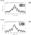
- Figs. 6A and 6B each show the signal intensity of the 39-th harmonic interference image obtained from the fundamental wave at the wavelength 650 nm.
- the horizontal axis represents the position on the Y axis of the two-dimensional CCD camera.
- Fig. 6A shows an interference image 300 of the first double slit 150 acquired in the first state ⁇ 1.
- Fig. 6B shows an interference image 302 of the second double slit 152 acquired in the second state ⁇ 2.
- the fringe position and the light intensity between the two indifference images i.e., the interference image 300 shown in Fig. 6A and the interference image 302 shown in Fig. 6B .
- the open-circle plots indicate an interference image acquired by measurement.
- the solid-line plots indicate an interference image obtained by calculation.
- Z 01 represents the distance between the double-slit plane and the grating plane, which is 0.72 m.
- Z 12 represents the distance between the grating plane and the image capture plane (screen plane) of the CCD array, which is 0.3 m.
- Z 01 and Z 12 are each handled as a constant value.
- a region that corresponds to a slit aperture provides a transmittance of 100%.
- a region that does not correspond to a slit aperture provides a transmittance of 0%.
- the aperture function f(x 0 ) is ideally represented by a step function having 0 and 1 with points of discontinuity at the aperture boundary.
- a double slit having an aperture width of 20 ⁇ m was employed.
- Focused ion beam (FIB) manufacturing involves manufacturing error. Accordingly, the slit width and the slit interval are not handled as constants. Instead, the slit width and the slit interval are each handled as a variable. Specifically, the slit width and the slit interval are calculated and employed such that the calculation values of the interference image obtained based on Expression (2) best match the measurement values (300, 302) acquired by measurement. Furthermore, in order to remove high-frequency components that are equal to or higher than the Nyquist frequency, the aperture function f(x 0 ) was replaced by an error function having a width of 1 ⁇ m.
- the harmonic light source provides a beam size of 10 ⁇ m or less. Accordingly, the electric field intensity is uniformly distributed in the apertures of the double slit 150 or 152 arranged at a distance of 44 cm from the light source.
- the spatial coherence of the harmonics in the apertures of the double slit can be assumed to be 100% based on the van Cittert-Zernike theorem (Non-patent document 32).
- the line width was measured. As a result of the measurement, it has been found that the width was sufficiently narrow to have a negligible effect. That is to say, degradation of the visibility due to the line width is negligible.
- the pointing of the fundamental wave focused on the neon gas as the nonlinear medium 4 for the harmonics and the phase of the interference image were simultaneously monitored. As a result, it has been confirmed that there is a clear correlation between them, i.e., a relation of 0.8 mrad/ ⁇ m.
- the focusing position drifts at a maximum speed of 4 ⁇ m/min. In this case, one measurement over 200 seconds involves the occurrence of an error on the order of 10 mrad. In order to eliminate the uncertainty due to this drift, the drift is suppressed using the following method.
- a stabilizing apparatus 120 monitors the positions of the short-pulse laser light at two points, i.e., at a position in the focusing optical system 116 at which the short-pulse laser light is provided as parallel light and at the focusing point, so as to control the mechanical state of the optical elements of the focusing optical system 116.
- the position of the fundamental wave S0 is monitored at two points, i.e., a point at which the fundamental wave S0 is provided as parallel light and at the focusing point, using position detector elements PSD1 and PSD2.
- two mirror holders 124 and 126 that form the focusing optical system 116 together with the mirror 118 are controlled by means of a piezo actuator, thereby providing stabilization using the two position detection elements.
- the focusing position was stabilized to 0.1 ⁇ m or less on average over 1 ⁇ 10 6 pulses. With such an arrangement providing such stabilization, this allows systematic error due to the drift of the focusing position of the fundamental wave to be suppressed to 0.08 mrad or less.
- the noise due to the dark current of the CCD camera is on the order of 0.0000175 A/D counts/pixel/sec. It can be assumed that the noise due to the dark current becomes sufficiently smaller than the photon shot noise after integration over 200 seconds. Accordingly, in this experiment, the noise due to the dark current is ignored.
- Each pixel of the CCD camera involves read noise.
- Read noise of 1.21 A/D counts/pixel occurs per pixel at a read rate of 50 kHz.
- analysis was made giving consideration to the signal integration in which the signal is integrated for each point over 15 pixels with the position that corresponds to the peak intensity as the center as described above, and the processing in which the signal is acquired by subtracting the background from the original signal.
- f represents the focal distance of the toroidal plane along the optical axis of the zero-order diffracted light, which is 0.3 m.
- the incident wavefront g and the phase term W originating due to the toroidal grating were re-investigated.
- Reports are known in which the wavefronts of harmonics generated by a Gaussian beam can be represented with high precision by a Gaussian beam (TEM00 mode) (Non-patent documents 33 and 34). From among the terms that represent the wavefront of the TEM00 mode, the component that changes with respect to a change x 0 on a plane that is orthogonal to the propagating direction is represented in the form of a quadratic function.
- the wavefront is not a plane wave. Rather, the wavefront exhibits dependence on the change x0 on the plane as represented by the following Expression (7).
- the first term represents the slope of the wavefront due to the toroidal grating.
- the second term represents the curvature due to the toroidal grating.
- ⁇ (in the slope term) and F (in the curvature term) are each handled as a variable dependent on the wavelength ⁇ .
- the detailed design of the grating has been black-boxed. Accordingly, higher-order phase terms than the above-described terms will not be described in the present disclosure.
- the variables described above are optimized so as to reproduce well the interference image 300 measured in the first state ⁇ 1,and calculates the shape of the interference image of both empty double slits using the least-square method.
- the calculation results are indicated by the solid line in Fig. 6A . It can be understood that there is agreement by more than two orders in the dynamic range between the calculation result and the measurement result.
- the fitting parameters (A, ⁇ , F, R) and the fluctuation P ⁇ of the light source are employed.
- ⁇ r 2 becomes a distribution from 1.6 to 6.4.
- the interference image 302 measured in the second state ⁇ 2 in which the sample 2 is in one slit of the double slit is evaluated using Expression (2).
- the aperture function of the slit with the sample 2 installed is modified by multiplying the L • exp(i ⁇ ) term using the electric field transmittance L and the phase difference ⁇ . Also in this case, it has been found that there is agreement of two or more orders in the dynamic range. It should be noted that, as the aberration and the incident wavefront, the values obtained by the measurement and analysis of the first state ⁇ 1 were used. As the fitting parameters, (A, L, ⁇ ) and the fluctuation P ⁇ of the light source are employed.
- the improved fitting model reduces ⁇ r2 to on the order of 1.6 to 6.4.
- systematic characteristics exist.
- Such non-random systematic residuals contribute to the uncertainties of the parameters as systematic error.
- the distribution of the systematic residuals is approximated as a normal distribution with a standard deviation of O rms (Non-patent document 36).
- the uncertainty thus obtained corresponds to a 68% confidence interval.
- the statistical uncertainty ⁇ stat also corresponds to a 68% confidence interval.
- the square root of the sum of squares of ⁇ syst and ⁇ stat is employed.
- Fig. 7 is a diagram showing ⁇ and L measured in the experiment. A clear spectrum structure having a peak at 72.8 eV is observed. This indicates the L-edge of aluminum.
- the oxide film has a very different refractive index. This leads to large uncertainty in the refractive index.
- Fig. 8 is a diagram showing the refractive index obtained from the experiment. The uncertainty of the film thickness contributes to each error bar in addition to the uncertainties of ⁇ and L. Fig. 8 shows the plots of refractive indexes reported in the past in addition to the plot of the error bars obtained by the optical constant measurement apparatus 100. Both the real part and the imaginary part of the refractive index agree with those reported by Birken (Non-patent document 7) at an energy around the L-edge. However, these values do not agree with the database of CXRO (The Center for X-ray Optics) and the results reported by Chang (Non-patent document 8).
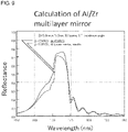
- Fig. 9 is a diagram showing the calculation results of the reflective index of an Al/Zr multilayer mirror.
- the optical constants of Zr the CXRO values are used.
- the optical constants of Al the optical constants measured by the optical constant measurement apparatus 100 and the CXRO values are used. It has been confirmed that, in a case of designing the multilayer mirror based on the optical constants thus measured in the experiment, this provides a significant difference on the order of 5 ⁇ 1%.
- the complex refractive index was quantitatively estimated as a parameter of the model function by modeling the double-slit interference image of the high-order harmonics.
- the statistical uncertainty of the measurement value was quantified by measurement.
- the design of the double slit was optimized so as to reduce the uncertainty of the complex refractive index to the minimum.
- the measurement results of the refractive index of aluminum in a range of 63 to 78 eV agree with those reported by Birken for both the real part and the imaginary part of the refractive index in the vicinity of the L-edge.
- the measurement results do not agree with CXRO and the results reported by Chang.
- the measurement results of the imaginary part of the refractive index in an energy range that is equal to or lower than the L-edge agree with the results reported by Gullikson.
- the measurement error was quantitatively estimated for the first time.
- the detection error of the phase shift was estimated to be on the order of 9 mrad in an energy range that is equal to or lower than the L-edge, and to be on the order of 13 mrad in an energy range that is higher than the L-edge.
- the accuracy was improved by two orders of magnitude for a double-slit interferometer based on high-order harmonics.
- this allows the reflective index of a multilayer mirror to be estimated within a precision range of ⁇ 1%.
- the measurement of the first interference image 300 may be omitted, i.e., only the second interference image 302 may be measured so as to calculate the optical constants of the sample.
- the method for determining the model (function) of the optical constant measurement apparatus 100 is not restricted to such an arrangement described in the embodiment. Also, any arrangement may be made so long as the actual measurement apparatus is represented with the highest accuracy by the functions g( ⁇ ), f( ⁇ ), and W(p) that represent the wavefront, the apertures of the double slit, and the grating.
- the present invention relates to a measurement technique for an optical constant such as a complex refractive index.
Landscapes
- Physics & Mathematics (AREA)
- Spectroscopy & Molecular Physics (AREA)
- General Physics & Mathematics (AREA)
- Health & Medical Sciences (AREA)
- Life Sciences & Earth Sciences (AREA)
- Chemical & Material Sciences (AREA)
- Analytical Chemistry (AREA)
- Biochemistry (AREA)
- General Health & Medical Sciences (AREA)
- Immunology (AREA)
- Pathology (AREA)
- Investigating Or Analysing Materials By Optical Means (AREA)
Applications Claiming Priority (2)
| Application Number | Priority Date | Filing Date | Title |
|---|---|---|---|
| US201962887077P | 2019-08-15 | 2019-08-15 | |
| PCT/JP2020/030878 WO2021029435A1 (ja) | 2019-08-15 | 2020-08-14 | 光学定数測定装置および光学定数の測定方法、光学定数の計算方法 |
Publications (3)
| Publication Number | Publication Date |
|---|---|
| EP4016060A1 true EP4016060A1 (de) | 2022-06-22 |
| EP4016060A4 EP4016060A4 (de) | 2023-07-26 |
| EP4016060B1 EP4016060B1 (de) | 2025-07-23 |
Family
ID=74569361
Family Applications (1)
| Application Number | Title | Priority Date | Filing Date |
|---|---|---|---|
| EP20851707.8A Active EP4016060B1 (de) | 2019-08-15 | 2020-08-14 | Messvorrichtung für optische konstante und verfahren zur berechnung einer optischen konstante |
Country Status (5)
| Country | Link |
|---|---|
| US (1) | US12241781B2 (de) |
| EP (1) | EP4016060B1 (de) |
| JP (1) | JP7646210B2 (de) |
| TW (1) | TWI864070B (de) |
| WO (1) | WO2021029435A1 (de) |
Families Citing this family (3)
| Publication number | Priority date | Publication date | Assignee | Title |
|---|---|---|---|---|
| TWI782822B (zh) * | 2021-12-16 | 2022-11-01 | 國立清華大學 | 利用掃描式同調光繞射的三維顯影方法及系統 |
| US12578652B2 (en) * | 2022-09-01 | 2026-03-17 | Taiwan Semiconductor Manufacturing Company, Ltd. | Photomask and methods for measuring and manufacturing the photomask |
| JP2024063855A (ja) * | 2022-10-27 | 2024-05-14 | 株式会社Screenホールディングス | 位相差測定装置および位相差測定方法 |
Family Cites Families (4)
| Publication number | Priority date | Publication date | Assignee | Title |
|---|---|---|---|---|
| TW201600901A (zh) * | 2014-06-19 | 2016-01-01 | 勝華科技股份有限公司 | 裝飾板以及觸控面板 |
| CN105115940B (zh) * | 2015-09-08 | 2017-10-20 | 福州大学 | 光学材料折射率曲线测量方法及装置 |
| US20170281102A1 (en) * | 2016-03-31 | 2017-10-05 | Weng-Dah Ken | Non-contact angle measuring apparatus, mission critical inspection apparatus, non-invasive diagnosis/treatment apparatus, method for filtering matter wave from a composite particle beam, non-invasive measuring apparatus, apparatus for generating a virtual space-time lattice, and fine atomic clock |
| CN108132230A (zh) * | 2018-03-05 | 2018-06-08 | 长春理工大学 | 一种液体折射率自动测量的装置及方法 |
-
2020
- 2020-08-14 EP EP20851707.8A patent/EP4016060B1/de active Active
- 2020-08-14 JP JP2021539316A patent/JP7646210B2/ja active Active
- 2020-08-14 WO PCT/JP2020/030878 patent/WO2021029435A1/ja not_active Ceased
- 2020-08-14 TW TW109127790A patent/TWI864070B/zh active
-
2022
- 2022-02-15 US US17/672,114 patent/US12241781B2/en active Active
Also Published As
| Publication number | Publication date |
|---|---|
| US12241781B2 (en) | 2025-03-04 |
| JP7646210B2 (ja) | 2025-03-17 |
| WO2021029435A1 (ja) | 2021-02-18 |
| JPWO2021029435A1 (de) | 2021-02-18 |
| EP4016060B1 (de) | 2025-07-23 |
| TW202120911A (zh) | 2021-06-01 |
| EP4016060A4 (de) | 2023-07-26 |
| TWI864070B (zh) | 2024-12-01 |
| US20220252453A1 (en) | 2022-08-11 |
Similar Documents
| Publication | Publication Date | Title |
|---|---|---|
| US12241781B2 (en) | Device and method for measuring optical constant | |
| Liu et al. | High-accuracy wavefront sensing for x-ray free electron lasers | |
| Rothhardt et al. | Table-top nanoscale coherent imaging with XUV light | |
| Quiney et al. | Diffractive imaging of highly focused X-ray fields | |
| CN110178087B (zh) | 减少准分子光源中的散斑 | |
| JP7021243B2 (ja) | 空間出力からスペクトル形状を回復する装置及び方法 | |
| Roling et al. | Time-dependent wave front propagation simulation of a hard x-ray split-and-delay unit: Towards a measurement of the temporal coherence properties of x-ray free electron lasers | |
| Shurvinton et al. | Development of multilayer monochromators for stripe-free X-ray imaging | |
| Merthe et al. | Methodology for optimal in situ alignment and setting of bendable optics for nearly diffraction-limited focusing of soft x-rays | |
| Yuan et al. | Cross-check of ex-situ and in-situ metrology of a bendable temperature stabilized KB mirror | |
| Yuan et al. | Development of in situ, at-wavelength metrology for soft X-ray nano-focusing | |
| Merthe et al. | An experimental apparatus for diffraction-limited soft x-ray nano-focusing | |
| Goldberg et al. | Ultra-high-accuracy optical testing: creating diffraction-limited short-wavelength optical systems | |
| Balyan | X-ray interferometric Fourier holography | |
| Yamada et al. | Ultimate condensation of hard X-ray free-electron laser reaching single-nanometre focus size and 1022 W/cm2 intensity | |
| Schäfer et al. | Wavefront and Coherence Characteristics of Extreme UV and Soft X-ray Sources | |
| Tadesse | Nanoscale coherent diffractive imaging using high-harmonic XUV sources | |
| Kimura et al. | Sub-micrometer spatial resolution Nomarski interferometer for time-resolved complex-amplitude imaging of femtosecond laser-induced air plasma | |
| Zürch | High-Resolution Extreme Ultraviolet Microscopy: Imaging of Artificial and Biological Specimens with Laser-Driven Ultrafast XUV Sources | |
| Niibe et al. | Development of EUV point diffraction interferometry using the NewSUBARU undulator radiation | |
| Levecq et al. | Recent developments in X-UV optics and X-UV diagnostics | |
| Le | Generation and application of coherent extreme ultraviolet radiation | |
| Goldberg et al. | Collaborative development of diffraction-limited beamline optical systems at US DOE light | |
| Zeitoun et al. | New techniques for the measurement of x-ray beam or x-ray optics quality | |
| Lötgering | Computational imaging methods for visible light and X-ray microscopy |
Legal Events
| Date | Code | Title | Description |
|---|---|---|---|
| STAA | Information on the status of an ep patent application or granted ep patent |
Free format text: STATUS: THE INTERNATIONAL PUBLICATION HAS BEEN MADE |
|
| PUAI | Public reference made under article 153(3) epc to a published international application that has entered the european phase |
Free format text: ORIGINAL CODE: 0009012 |
|
| STAA | Information on the status of an ep patent application or granted ep patent |
Free format text: STATUS: REQUEST FOR EXAMINATION WAS MADE |
|
| 17P | Request for examination filed |
Effective date: 20220315 |
|
| AK | Designated contracting states |
Kind code of ref document: A1 Designated state(s): AL AT BE BG CH CY CZ DE DK EE ES FI FR GB GR HR HU IE IS IT LI LT LU LV MC MK MT NL NO PL PT RO RS SE SI SK SM TR |
|
| DAV | Request for validation of the european patent (deleted) | ||
| DAX | Request for extension of the european patent (deleted) | ||
| REG | Reference to a national code |
Ref country code: DE Ref legal event code: R079 Free format text: PREVIOUS MAIN CLASS: G01N0023020000 Ipc: G01N0021450000 Ref country code: DE Ref legal event code: R079 Ref document number: 602020055175 Country of ref document: DE Free format text: PREVIOUS MAIN CLASS: G01N0023020000 Ipc: G01N0021450000 |
|
| A4 | Supplementary search report drawn up and despatched |
Effective date: 20230626 |
|
| RIC1 | Information provided on ipc code assigned before grant |
Ipc: G01J 3/28 20060101ALI20230620BHEP Ipc: G01J 3/18 20060101ALI20230620BHEP Ipc: G01J 3/10 20060101ALI20230620BHEP Ipc: G01J 3/02 20060101ALI20230620BHEP Ipc: G01N 21/45 20060101AFI20230620BHEP |
|
| GRAP | Despatch of communication of intention to grant a patent |
Free format text: ORIGINAL CODE: EPIDOSNIGR1 |
|
| STAA | Information on the status of an ep patent application or granted ep patent |
Free format text: STATUS: GRANT OF PATENT IS INTENDED |
|
| RIC1 | Information provided on ipc code assigned before grant |
Ipc: G01J 3/28 20060101ALI20250206BHEP Ipc: G01J 3/18 20060101ALI20250206BHEP Ipc: G01J 3/10 20060101ALI20250206BHEP Ipc: G01J 3/02 20060101ALI20250206BHEP Ipc: G01N 21/45 20060101AFI20250206BHEP |
|
| INTG | Intention to grant announced |
Effective date: 20250219 |
|
| GRAS | Grant fee paid |
Free format text: ORIGINAL CODE: EPIDOSNIGR3 |
|
| GRAA | (expected) grant |
Free format text: ORIGINAL CODE: 0009210 |
|
| STAA | Information on the status of an ep patent application or granted ep patent |
Free format text: STATUS: THE PATENT HAS BEEN GRANTED |
|
| AK | Designated contracting states |
Kind code of ref document: B1 Designated state(s): AL AT BE BG CH CY CZ DE DK EE ES FI FR GB GR HR HU IE IS IT LI LT LU LV MC MK MT NL NO PL PT RO RS SE SI SK SM TR |
|
| REG | Reference to a national code |
Ref country code: GB Ref legal event code: FG4D |
|
| REG | Reference to a national code |
Ref country code: CH Ref legal event code: EP |
|
| REG | Reference to a national code |
Ref country code: DE Ref legal event code: R096 Ref document number: 602020055175 Country of ref document: DE |
|
| REG | Reference to a national code |
Ref country code: IE Ref legal event code: FG4D |
|
| PGFP | Annual fee paid to national office [announced via postgrant information from national office to epo] |
Ref country code: NL Payment date: 20250825 Year of fee payment: 6 |
|
| PGFP | Annual fee paid to national office [announced via postgrant information from national office to epo] |
Ref country code: DE Payment date: 20250828 Year of fee payment: 6 |
|
| REG | Reference to a national code |
Ref country code: NL Ref legal event code: FP |
|
| PG25 | Lapsed in a contracting state [announced via postgrant information from national office to epo] |
Ref country code: PT Free format text: LAPSE BECAUSE OF FAILURE TO SUBMIT A TRANSLATION OF THE DESCRIPTION OR TO PAY THE FEE WITHIN THE PRESCRIBED TIME-LIMIT Effective date: 20251124 |
|
| REG | Reference to a national code |
Ref country code: AT Ref legal event code: MK05 Ref document number: 1816884 Country of ref document: AT Kind code of ref document: T Effective date: 20250723 |
|
| PG25 | Lapsed in a contracting state [announced via postgrant information from national office to epo] |
Ref country code: IS Free format text: LAPSE BECAUSE OF FAILURE TO SUBMIT A TRANSLATION OF THE DESCRIPTION OR TO PAY THE FEE WITHIN THE PRESCRIBED TIME-LIMIT Effective date: 20251123 |
|
| PG25 | Lapsed in a contracting state [announced via postgrant information from national office to epo] |
Ref country code: NO Free format text: LAPSE BECAUSE OF FAILURE TO SUBMIT A TRANSLATION OF THE DESCRIPTION OR TO PAY THE FEE WITHIN THE PRESCRIBED TIME-LIMIT Effective date: 20251023 |
|
| REG | Reference to a national code |
Ref country code: LT Ref legal event code: MG9D |
|
| PG25 | Lapsed in a contracting state [announced via postgrant information from national office to epo] |
Ref country code: AT Free format text: LAPSE BECAUSE OF FAILURE TO SUBMIT A TRANSLATION OF THE DESCRIPTION OR TO PAY THE FEE WITHIN THE PRESCRIBED TIME-LIMIT Effective date: 20250723 |
|
| PG25 | Lapsed in a contracting state [announced via postgrant information from national office to epo] |
Ref country code: FI Free format text: LAPSE BECAUSE OF FAILURE TO SUBMIT A TRANSLATION OF THE DESCRIPTION OR TO PAY THE FEE WITHIN THE PRESCRIBED TIME-LIMIT Effective date: 20250723 |
|
| PG25 | Lapsed in a contracting state [announced via postgrant information from national office to epo] |
Ref country code: HR Free format text: LAPSE BECAUSE OF FAILURE TO SUBMIT A TRANSLATION OF THE DESCRIPTION OR TO PAY THE FEE WITHIN THE PRESCRIBED TIME-LIMIT Effective date: 20250723 |
|
| PG25 | Lapsed in a contracting state [announced via postgrant information from national office to epo] |
Ref country code: GR Free format text: LAPSE BECAUSE OF FAILURE TO SUBMIT A TRANSLATION OF THE DESCRIPTION OR TO PAY THE FEE WITHIN THE PRESCRIBED TIME-LIMIT Effective date: 20251024 |
|
| PG25 | Lapsed in a contracting state [announced via postgrant information from national office to epo] |
Ref country code: SE Free format text: LAPSE BECAUSE OF FAILURE TO SUBMIT A TRANSLATION OF THE DESCRIPTION OR TO PAY THE FEE WITHIN THE PRESCRIBED TIME-LIMIT Effective date: 20250723 |
|
| PG25 | Lapsed in a contracting state [announced via postgrant information from national office to epo] |
Ref country code: LV Free format text: LAPSE BECAUSE OF FAILURE TO SUBMIT A TRANSLATION OF THE DESCRIPTION OR TO PAY THE FEE WITHIN THE PRESCRIBED TIME-LIMIT Effective date: 20250723 |
|
| PG25 | Lapsed in a contracting state [announced via postgrant information from national office to epo] |
Ref country code: BG Free format text: LAPSE BECAUSE OF FAILURE TO SUBMIT A TRANSLATION OF THE DESCRIPTION OR TO PAY THE FEE WITHIN THE PRESCRIBED TIME-LIMIT Effective date: 20250723 Ref country code: PL Free format text: LAPSE BECAUSE OF FAILURE TO SUBMIT A TRANSLATION OF THE DESCRIPTION OR TO PAY THE FEE WITHIN THE PRESCRIBED TIME-LIMIT Effective date: 20250723 |
|
| PG25 | Lapsed in a contracting state [announced via postgrant information from national office to epo] |
Ref country code: RS Free format text: LAPSE BECAUSE OF FAILURE TO SUBMIT A TRANSLATION OF THE DESCRIPTION OR TO PAY THE FEE WITHIN THE PRESCRIBED TIME-LIMIT Effective date: 20251023 |
|
| PG25 | Lapsed in a contracting state [announced via postgrant information from national office to epo] |
Ref country code: ES Free format text: LAPSE BECAUSE OF FAILURE TO SUBMIT A TRANSLATION OF THE DESCRIPTION OR TO PAY THE FEE WITHIN THE PRESCRIBED TIME-LIMIT Effective date: 20250723 |
|
| PG25 | Lapsed in a contracting state [announced via postgrant information from national office to epo] |
Ref country code: RO Free format text: LAPSE BECAUSE OF FAILURE TO SUBMIT A TRANSLATION OF THE DESCRIPTION OR TO PAY THE FEE WITHIN THE PRESCRIBED TIME-LIMIT Effective date: 20250723 |
|
| REG | Reference to a national code |
Ref country code: CH Ref legal event code: H13 Free format text: ST27 STATUS EVENT CODE: U-0-0-H10-H13 (AS PROVIDED BY THE NATIONAL OFFICE) Effective date: 20260324 |
|
| PG25 | Lapsed in a contracting state [announced via postgrant information from national office to epo] |
Ref country code: SM Free format text: LAPSE BECAUSE OF FAILURE TO SUBMIT A TRANSLATION OF THE DESCRIPTION OR TO PAY THE FEE WITHIN THE PRESCRIBED TIME-LIMIT Effective date: 20250723 |
|
| PG25 | Lapsed in a contracting state [announced via postgrant information from national office to epo] |
Ref country code: DK Free format text: LAPSE BECAUSE OF FAILURE TO SUBMIT A TRANSLATION OF THE DESCRIPTION OR TO PAY THE FEE WITHIN THE PRESCRIBED TIME-LIMIT Effective date: 20250723 |
|
| PG25 | Lapsed in a contracting state [announced via postgrant information from national office to epo] |
Ref country code: IT Free format text: LAPSE BECAUSE OF FAILURE TO SUBMIT A TRANSLATION OF THE DESCRIPTION OR TO PAY THE FEE WITHIN THE PRESCRIBED TIME-LIMIT Effective date: 20250723 Ref country code: LU Free format text: LAPSE BECAUSE OF NON-PAYMENT OF DUE FEES Effective date: 20250814 |
|
| PG25 | Lapsed in a contracting state [announced via postgrant information from national office to epo] |
Ref country code: CZ Free format text: LAPSE BECAUSE OF FAILURE TO SUBMIT A TRANSLATION OF THE DESCRIPTION OR TO PAY THE FEE WITHIN THE PRESCRIBED TIME-LIMIT Effective date: 20250723 Ref country code: CH Free format text: LAPSE BECAUSE OF NON-PAYMENT OF DUE FEES Effective date: 20250831 |
|
| PG25 | Lapsed in a contracting state [announced via postgrant information from national office to epo] |
Ref country code: SK Free format text: LAPSE BECAUSE OF FAILURE TO SUBMIT A TRANSLATION OF THE DESCRIPTION OR TO PAY THE FEE WITHIN THE PRESCRIBED TIME-LIMIT Effective date: 20250723 Ref country code: EE Free format text: LAPSE BECAUSE OF FAILURE TO SUBMIT A TRANSLATION OF THE DESCRIPTION OR TO PAY THE FEE WITHIN THE PRESCRIBED TIME-LIMIT Effective date: 20250723 |