EP4016061A1 - Procédé de commande d'un système à rayons x - Google Patents
Procédé de commande d'un système à rayons x Download PDFInfo
- Publication number
- EP4016061A1 EP4016061A1 EP22155302.7A EP22155302A EP4016061A1 EP 4016061 A1 EP4016061 A1 EP 4016061A1 EP 22155302 A EP22155302 A EP 22155302A EP 4016061 A1 EP4016061 A1 EP 4016061A1
- Authority
- EP
- European Patent Office
- Prior art keywords
- ray
- recording
- data set
- projection
- partial
- Prior art date
- Legal status (The legal status is an assumption and is not a legal conclusion. Google has not performed a legal analysis and makes no representation as to the accuracy of the status listed.)
- Granted
Links
Images
Classifications
-
- G—PHYSICS
- G01—MEASURING; TESTING
- G01N—INVESTIGATING OR ANALYSING MATERIALS BY DETERMINING THEIR CHEMICAL OR PHYSICAL PROPERTIES
- G01N23/00—Investigating or analysing materials by the use of wave or particle radiation, e.g. X-rays or neutrons, not covered by groups G01N3/00 – G01N17/00, G01N21/00 or G01N22/00
- G01N23/02—Investigating or analysing materials by the use of wave or particle radiation, e.g. X-rays or neutrons, not covered by groups G01N3/00 – G01N17/00, G01N21/00 or G01N22/00 by transmitting the radiation through the material
- G01N23/04—Investigating or analysing materials by the use of wave or particle radiation, e.g. X-rays or neutrons, not covered by groups G01N3/00 – G01N17/00, G01N21/00 or G01N22/00 by transmitting the radiation through the material and forming images of the material
- G01N23/046—Investigating or analysing materials by the use of wave or particle radiation, e.g. X-rays or neutrons, not covered by groups G01N3/00 – G01N17/00, G01N21/00 or G01N22/00 by transmitting the radiation through the material and forming images of the material using tomography, e.g. computed tomography [CT]
-
- G—PHYSICS
- G06—COMPUTING OR CALCULATING; COUNTING
- G06T—IMAGE DATA PROCESSING OR GENERATION, IN GENERAL
- G06T12/00—Tomographic reconstruction from projections
-
- G—PHYSICS
- G06—COMPUTING OR CALCULATING; COUNTING
- G06T—IMAGE DATA PROCESSING OR GENERATION, IN GENERAL
- G06T12/00—Tomographic reconstruction from projections
- G06T12/10—Image preprocessing, e.g. calibration, positioning of sources or scatter correction
-
- G—PHYSICS
- G06—COMPUTING OR CALCULATING; COUNTING
- G06T—IMAGE DATA PROCESSING OR GENERATION, IN GENERAL
- G06T7/00—Image analysis
- G06T7/0002—Inspection of images, e.g. flaw detection
- G06T7/0012—Biomedical image inspection
-
- G—PHYSICS
- G01—MEASURING; TESTING
- G01N—INVESTIGATING OR ANALYSING MATERIALS BY DETERMINING THEIR CHEMICAL OR PHYSICAL PROPERTIES
- G01N2223/00—Investigating materials by wave or particle radiation
- G01N2223/40—Imaging
- G01N2223/401—Imaging image processing
-
- G—PHYSICS
- G06—COMPUTING OR CALCULATING; COUNTING
- G06T—IMAGE DATA PROCESSING OR GENERATION, IN GENERAL
- G06T2207/00—Indexing scheme for image analysis or image enhancement
- G06T2207/10—Image acquisition modality
- G06T2207/10072—Tomographic images
-
- G—PHYSICS
- G06—COMPUTING OR CALCULATING; COUNTING
- G06T—IMAGE DATA PROCESSING OR GENERATION, IN GENERAL
- G06T2207/00—Indexing scheme for image analysis or image enhancement
- G06T2207/10—Image acquisition modality
- G06T2207/10116—X-ray image
Definitions
- Embodiments of the present invention relate to a method and a device for operating an X-ray system, such as a CT system in particular. Further exemplary embodiments relate to an X-ray or CT system comprising a corresponding operating device.
- CT systems X-ray computer tomography systems
- tasks such as non-destructive material testing are carried out.
- applications such as escalation testing, i.e. manual testing of large components with a wide variety of geometries as soon as critical errors are suspected
- manual non-destructive testing using X-ray technology is often used.
- These are usually laboratory systems or portal systems.
- the inspector sometimes has to design and install complicated concepts for fixtures or manually guide the X-ray components to the inspection area of the component (ROI).
- a CT is often not possible with this approach or only with poor image quality, since these systems cannot generate enough data for a 3D reconstruction or the installed mounts appear as foreign objects in the reconstruction.
- the object of the present invention is to create an improved operating concept for X-ray systems.
- Exemplary embodiments of the present invention provide a method for operating an X-ray system, the starting point being an X-ray system which has at least one manipulator, such as a robot or linear drive, and an X-ray source and an x-ray detector. Either the object to be examined or the X-ray source or the X-ray detector is preferably arranged on the manipulator. The unit arranged on the manipulator determines the trajectory based on the different positions to be assumed (depending on the manipulator position).
- a first position on the trajectory is explained manually, ie by the user using virtual input means (virtual reality input means or augmented reality input means), so that this position can either be approached by the X-ray system in order to record the object to perform from the first position, or the recording can be simulated.
- This step is repeated for a second position on the trajectory.
- An (X-ray) exposure is recorded or simulated from each of these two positions in order to obtain two X-ray projections.
- one of the or both x-ray projections eg using a live image
- information describing the x-ray projections is output so that the user receives feedback as to whether additional or different x-ray projections are necessary.
- the x-ray system is a CT system.
- the method includes the optional step of reconstructing a CT data record based on the at least two x-ray images. Proceeding from the two (first and second) x-ray projections, the reconstruction of the CT data record can then already be started, with two x-ray projections usually only being able to obtain a partial CT data record. In this case, the partial CT data set is output to the user (or information about it), so that he can decide which other angles in space should still be approached.
- Embodiments of the present invention are based on the finding that an X-ray system or a CT system can be controlled very easily and intuitively if (first) the individual positions on the trajectory can be set directly by the user and if (second) the users direct feedback on the data measured so far, e.g. B. based on the first radiograph, an incomplete reconstruction in the case of the CT system or based on data based on the previous recordings.
- B. based on the first radiograph
- the virtual input means are implemented, for example, by a sensor glove or by using the x-ray system actuators as input means.
- the sensor glove With the sensor glove, the movable components of the X-ray system are positioned virtually in space (keyword virtual reality, but also augmented reality).
- the actuators With the concept of using the actuators as sensors, the movable components of the X-ray system can be shifted accordingly, which can be implemented with most manipulators/robots using the so-called "force-free mode", so that the different positions on the trajectory can be set directly . This is referred to as "hand-guided tactile movement".
- these positions are correspondingly stored both in the virtual and in the real positioning, so that the positions can be approached again at a later point in time or during the measurement to be carried out. Proceeding from such virtual input means, it becomes clear that they also make it possible to easily determine and approach complex trajectories that do not correspond to analytically describable standard geometries, such as circles and helixes. The operator does not have to have the appropriate specialist knowledge to operate the system, such as e.g. B. in relation to the individual parameters of the trajectory have. Such a robot-assisted X-ray/CT system can be operated as easily as a laboratory system for circular CT applications.
- the first radiographs, the partial CT data set, ie the reconstructed voxel model can be given to the user as feedback, for example via a screen or via virtual reality tools, such as e.g. B. 3D glasses are issued.
- virtual reality tools such as e.g. B. 3D glasses are issued.
- a classic task of X-ray systems in workshop testing is to identify defects, such as e.g. B. to detect cavities in the material. Therefore, according to further exemplary embodiments, the evaluation result can also be given to the user as feedback instead of the X-ray exposure.
- the method thus includes the step of manually specifying a further position and recording or simulating the recording from the further position.
- the iterative supplementing of the data set for the CT/X-ray exposure saves a great deal of time in the manual escalation check, since it can be avoided that an unnecessarily large number of X-ray exposures or X-ray exposures are taken from positions without additional information content.
- first and/or second position of the trajectory are defined by the position of the x-ray source and x-ray detector relative to the object or relative to one another.
- a method for an X-ray system which comprises, for example, two (e.g. multi-part) robots, one robot carrying the X-ray source and the other robot carrying the X-ray detector, so that they can be moved relative to one another and in particular around the Object are movable around.
- the method can also be carried out by a device for operating an x-ray system.
- This device then includes the virtual input means for defining the first and/or second position for the x-ray system on the trajectory, means for recording and/or simulating the recording from the first and/or second position.
- the device also includes output means such.
- a further exemplary embodiment relates to an X-ray system and a CT system with precisely this device.
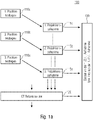
- Fig. 1a 12 shows a method 100 for operating an X-ray system, here for example a CT system, which comprises a total of six basic steps 110a, 115a, 110b, 115b, 120. These steps can be subdivided into purely manual steps, ie steps carried out by the user and at least preferably automatically.
- Steps 110a and 115a are coupled to each other.
- step 110a represents a manual step, namely the determination of a first position for the manipulator on the trajectory.
- a sensor glove a glove monitored by a camera or a pointing element monitored by a camera.
- a virtual input means is a means for marking a position in space.
- a first recording is then taken or at least simulated. This takes place in a step 115a.
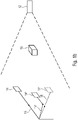
- recording or simulating the recording is just from the first Position assumed and received a first X-ray projection as a result. For example, this first position is in Fig. 1b shown.
- Fig. 1b 12 shows an X-ray system 10 with a fixed X-ray source 12 and a movable detector 14, with an object 16 to be examined being arranged between the movable detector 14 and the X-ray source 12.
- the movable detector 14 can be moved around the object 16 or around the X-ray source 12 with the aid of a manipulator, here a simple single-joint manipulator 18 with a swivel arm.
- the first position of the manipulator 18 and thus also the first position of the detector 14 or generally the first position of the elements 12, 14 and 16 relative to one another is in Fig. 1b shown with solid lines. Starting from this relative position of the elements 12, 14, 16 to one another, the first projection recording is taken.
- the second position is determined in a next step 110b, which is comparable to step 110a, so that the second exposure can then be taken or recorded in step 115b (comparable to step 115a). , can be simulated to obtain the second X-ray projection.
- This second position of the manipulator is in the Fig. 1b by means of dashed lines and the reference number 18'. This also results in the second position of the x-ray detector 14'. As a result, the second x-ray projection then represents the object 16 from a different position, for example from a different angle.
- step 130 the same is displayed for the user, so that the latter receives direct feedback and, based on this, he can decide whether further Recordings are necessary, for example because the defect sought in the object 16 is not contained in the section that was taken with the recording in step 115a, or based on this he can plan the next positions (cf. step 110b).
- step 130 it would also be conceivable for the user not to receive the graphic representation of the recording at all, but only information that provides information about the recording.
- the two radiographs are combined so that a CT reconstruction can take place.
- This CT reconstruction is then carried out in the subsequent step 120, in which the at least two x-ray projections are combined with one another.
- a voxel model for representing the 3D volume of the object 16 including the attenuation coefficients per volume fraction or a model for identifying 2D surfaces of the object 16 can be obtained.
- the CT data record can also be evaluated immediately, e.g. B. to the effect that a direct identification of blowholes in the volume of the object 16 is possible.
- step 130 the partial CT data set, i. H. i.e. the incompletely reconstructed model, so that the user receives direct visual feedback as to whether the previously taken or planned positions on the trajectory are sufficient or not. Based on this feedback, the user can then decide whether to take further reconstruction exposures (cf. optional steps 110c and 115c).
- step 110c (optional step) in order to define a third position on the trajectory.
- a third projection recording is then taken in step 115c, which is then either displayed directly in continuous step 130 (2D X-ray case) or, in the case of CT, is added to the repetition of step 120 for the reconstruction and in step 130 again to the user is issued.
- steps 115a, 115b, 120 and 130 are carried out automatically in accordance with exemplary embodiments.
- the procedure presented describes an interactive operating concept for X-ray systems.
- This is an intuitive and feedback-based variant of operating X-ray systems with the help of external control devices such as gloves, virtual/VR glasses, joysticks, etc.
- the advantage of this method is that the user receives direct feedback about the current result from the data measured so far, e.g. through a kind of live image, through a visualization of the reconstructed data set or also information about evaluation parameters, e.g. dimensions regarding image quality.
- the method is therefore a combination of operating a system and direct feedback of the measured data, i.e. the user can decide directly whether and when the available measurement data are sufficient to be able to solve a given task.
- the industrial X-ray inspection applications that are the focus here, e.g influence on the object under investigation.
- step 110c further positions can be approached and X-ray projections can be taken from these (cf. step 115c).
- IN Fig. 1b such a further position is illustrated by means of dotted lines (cf. manipulator 18'' and detector 14'').
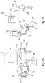
- Figure 2a a first configuration of the CT system, ie a first position while Figure 2b represents a second configuration (second position).
- Figure 2a shows a CT system 10* with a first robot 18a* and a second robot 18b*.
- the X-ray detector 14* is arranged on the first robot 18a*, while the radiation source 12* is arranged on the second robot 18b*.
- Both robots 18a* and 18b* are multi-part robots, so that the X-ray detector 14* and the radiation source 12* can be moved independently of one another.
- the object 14* to be examined is arranged between the two elements 12* and 14*.
- the degrees of freedom of the robots 18a* and 18b* allow the object 16* to be imaged from substantially all possible perspectives around it and at different distances from it.
- FIG. 2a A first position of the two robots 18a* and 18b* is shown, which corresponds to the first position on the trajectory of the CT system 10*.
- This first position is defined by the user 30 standing next to him, in that he uses VR input means 32 to define the pose of both the robot 18a* and the robot 18b*.
- the VR input means 32 are realized by two pointing means, here pointing sticks 32a and 32b, which the user 30 can guide freely in space.
- This position of the pointing position 32a and 32b and/or the orientation of the pointing point 32a and 32b in space is transmitted directly to the CT system 10* by means of a controller (not shown) and the robots 18a* and 18b* are aligned on this basis.
- a controller not shown
- the robots 18a* and 18b* are aligned on this basis.
- Figure 2b again represents the X-ray system 10*.
- the alignment of the robots 18a* and 18b* is also dependent on the posture of the user 30.
- the user 30 holds the pointing element 32a (right hand) vertically upwards, so that as a result the robot arm of the Robot 18a* is oriented straight up vertically, with the consequence that the detector 14* is straight compared to the configuration Figure 2a positioned higher up in the room.
- the user 30 stops in the representation of Figure 2b the second pointer 32b slightly angled, which has the consequence that the robot arm of the robot 18b *, at least compared to the configuration Figure 2a , is angled and consequently the X-ray source 12* is also closer to the object 16*.
- a second X-ray position is then taken in this second position and the reconstruction result is displayed again via the display means 40 .
- the shadow 42 but also a contour 42' can be displayed, so that the user receives direct feedback about the manipulation carried out.
- FIG. 2a and 2b The functionality of this embodiment Figures 2a and 2b can be described as follows: The user is thus able to move the system "by hand" until the 3D data available to him are sufficient for an assessment.
- the user 30 can mark the position as a recording position, for example using a button, so that either a recording is triggered using the CT system or the position is at least stored.
- the concept makes it possible to react to a wide variety of component geometries with little effort, such as modifications to the system or complex path planning. Manually generated trajectories can be saved and run again if necessary.
- the VR input means 30 are pointers, for example.
- other input means such as e.g. B. Gloves that are tracked by a camera or, in general, pure camera tracking or sensor gloves can be used. Such gloves in combination with a 3D display, e.g. via 3D glasses, make sense especially if not only the pure position and orientation of the robot or the attached X-ray source/sensor, but also an angular position of the robot is to be controlled.
- joysticks or sticks in general such as those known from game consoles, could also be used as VR input means. All such VR input means have in common that a movement of the user can be converted into a movement of at least one of the robots 18a* or 18b* or generally of the CT system with the aid of a calculation unit.
- the VR input means could be implemented by the robots themselves, for example by switching them to the so-called “free movement mode” and allowing the user to easily move them by hand.
- the method can be used effectively in particular for robot-assisted computed tomography systems, since here, as a rule, two or more industrial robots are positioned freely in space and the x-ray components are attached to them manually.
- Such systems are usually designed for the X-ray examination of very large objects such as aircraft components (wings) or car bodies, which due to their shape do not allow trajectories with straight (circular) movements.
- the operation and path planning (including any points in space around the object) for such systems is usually highly complex and cannot be solved cost-effectively for constantly changing requirements. This problem can be solved efficiently with the help of an interactive operating concept. Even complex tracks can be specifically created and checked for quality. In this context, quality means that the generated data deliver the desired results corresponding to the application.
- the x-ray source and/or x-ray detector are coupled to the manipulator or robot and are moved by the same around the object or relative to the object
- the object itself can be moved by means of a manipulator, such as a robot or linear drive (relative to the, for example, fixed X-ray source and/or the, for example, fixed X-ray detector) in order to move to the individual positions on the trajectory.
- a manipulator such as a robot or linear drive
- all three elements object, x-ray source and x-ray detector
- a second aspect with reference to the first aspect has a method 100, wherein the X-ray system 10, 10* is a CT system, and the method includes the step of beginning 120 the reconstruction of the CT data set on the basis of the first and second X-ray projection to obtain a partial CT data set; and wherein in the step of displaying 130 the first and the second x-ray projection or the information derived from the first and second x-ray projection includes displaying the partial CT data set or information describing the partial CT data set.
- a third aspect with reference to the second aspect has a method 100, wherein the partial CT data set is an incomplete reconstruction or an evaluation of the incomplete reconstruction with regard to an examination task.
- a fourth aspect with reference to the first to third aspect has a method 100, wherein the information derived from the first and second X-ray projection or the information describing the partial CT data set contains information regarding the resolution of the X-ray exposure or the CT data set or information regarding the quality of the X-ray recording or the CT data set.
- a fifth aspect with reference to the first to fourth aspects, comprises a method 100, the method 100 including the further steps of manually specifying a further position for the X-ray system 10, 10* using the virtual input means 30 and recording or simulating the recording of the object 16 using the X-ray system 10, 10* from the further position in order to obtain a further projection.
- a sixth aspect with reference to the fifth aspect has a method 100, wherein the steps are repeated until the X-ray exposure or the partial CT data set corresponds to a predetermined quality and/or resolution.
- a seventh aspect with reference to the first to sixth aspect has a method 100, wherein the method 100 includes the step of moving to the first position before recording or simulating 115a the recording from the first position, and wherein the method 100 includes the step of Approaching the second position before recording or simulating 115b the recording from the second position.
- An eighth aspect with reference to the first to seventh aspect has a method 100, wherein the manipulator 18, 18*a, 18b* comprises a robot or multi-articulated robot; and or wherein the first and/or second position are defined by the pose of the robot or by the poses of the multiple limbs of the multiple limb robot.
- a tenth aspect with reference to the first to ninth aspect has a method 100, wherein the manipulator 18, 18*a, 18b* is designed to move the object 16 move and/or to move the object 16 relative to the X-ray source 12, 12* and/or to the X-ray detector 14, 14* in order to approach the first position 18 and/or the second position 18' on the trajectory.
- An eleventh aspect with reference to the first to tenth aspect has a method 100, wherein the first and/or second position 18' of the trajectory is determined by the position of the X-ray source 12, 12* and of the X-ray detector 14, 14* relative to the object 16 and/or defined relative to each other.
- a twelfth aspect with reference to the first to eleventh aspect has a method 100, wherein the virtual input means 30 virtual reality input means, augmented reality input means, at least one sensor glove and/or at least one pointing element for marking a position in the 3D encompass space.
- a thirteenth aspect with reference to the first to twelfth aspect has a method 100, wherein the virtual input means 30 are formed by the manipulator 18, 18*a, 18b* itself, so that a manual movement of the manipulator 18, 18*a, 18b* is understood as input.
- a fourteenth aspect with reference to the first to thirteenth aspects has a method 100, wherein a virtual input means is provided for each manipulator.
- a fifteenth aspect with reference to the first to fourteenth aspects has a method 100, wherein the x-ray source 12, 12* and the x-ray detector 14, 14* are designed for continuous exposure.
- a sixteenth aspect with reference to the first to fifteenth aspect has a method 100, wherein the recording of the object 16 by means of the x-ray system 10, 10* takes place continuously from the first and second position; and the display 130 of the first and second X-ray projection takes place as a live recording.
- a nineteenth aspect has a computer program with a program code for performing the method 100 according to one of the first to eighteenth aspects when the method 100 runs on a computer.
- a twenty-second aspect has an X-ray system 10, 10*, which comprises a device according to the twentieth or twenty-first aspect.
- a twenty-third aspect with reference to the twenty-second aspect has an X-ray system 10, 10* which is designed as a CT system and includes a calculation unit for reconstructing the X-ray image based on the first and second X-ray projection in order to produce a partial X-ray image to obtain.
- aspects have been described in the context of a device, it is understood that these aspects also represent a description of the corresponding method, so that a block or a component of a device is also to be understood as a corresponding method step or as a feature of a method step. Similarly, aspects described in connection with or as a method step also constitute a description of a corresponding block or detail or feature of a corresponding device.
- Some or all of the method steps may be performed by hardware apparatus (or using a hardware Apparatus), such as a microprocessor, a programmable computer, or an electronic circuit. In some embodiments, some or more of the essential process steps can be performed by such an apparatus.
- embodiments of the invention may be implemented in hardware or in software. Implementation can be performed using a digital storage medium such as a floppy disk, DVD, Blu-ray Disc, CD, ROM, PROM, EPROM, EEPROM or FLASH memory, hard disk or other magnetic or optical memory, on which electronically readable control signals are stored, which can interact or interact with a programmable computer system in such a way that the respective method is carried out. Therefore, the digital storage medium can be computer-readable.
- a digital storage medium such as a floppy disk, DVD, Blu-ray Disc, CD, ROM, PROM, EPROM, EEPROM or FLASH memory, hard disk or other magnetic or optical memory, on which electronically readable control signals are stored, which can interact or interact with a programmable computer system in such a way that the respective method is carried out. Therefore, the digital storage medium can be computer-readable.
- some embodiments according to the invention comprise a data carrier having electronically readable control signals capable of interacting with a programmable computer system in such a way that one of the methods described herein is carried out.
- embodiments of the present invention can be implemented as a computer program product with a program code, wherein the program code is effective to perform one of the methods when the computer program product runs on a computer.
- the program code can also be stored on a machine-readable carrier, for example.
- exemplary embodiments include the computer program for performing one of the methods described herein, the computer program being stored on a machine-readable carrier.
- an exemplary embodiment of the method according to the invention is therefore a computer program that has a program code for performing one of the methods described herein when the computer program runs on a computer.
- a further exemplary embodiment of the method according to the invention is therefore a data carrier (or a digital storage medium or a computer-readable medium) on which the computer program for carrying out one of the methods described herein is recorded.
- a further exemplary embodiment of the method according to the invention is therefore a data stream or a sequence of signals which represents the computer program for carrying out one of the methods described herein.
- the data stream or sequence of signals may be configured to be transferred over a data communication link, such as the Internet.
- Another embodiment includes a processing device, such as a computer or programmable logic device, configured or adapted to perform any of the methods described herein.
- a processing device such as a computer or programmable logic device, configured or adapted to perform any of the methods described herein.
- Another embodiment includes a computer on which the computer program for performing one of the methods described herein is installed.
- a further exemplary embodiment according to the invention comprises a device or a system which is designed to transmit a computer program for carrying out at least one of the methods described herein to a recipient.
- the transmission can take place electronically or optically, for example.
- the recipient may be a computer, mobile device, storage device, or similar device.
- the device or the system can, for example, comprise a file server for transmission of the computer program to the recipient.
- a programmable logic device e.g., a field programmable gate array, an FPGA
- a field programmable gate array may cooperate with a microprocessor to perform any of the methods described herein.
- the methods are performed on the part of any hardware device. This can be hardware that can be used universally, such as a computer processor (CPU), or hardware that is specific to the method, such as an ASIC.
Landscapes
- Engineering & Computer Science (AREA)
- Health & Medical Sciences (AREA)
- Physics & Mathematics (AREA)
- General Physics & Mathematics (AREA)
- Theoretical Computer Science (AREA)
- Nuclear Medicine, Radiotherapy & Molecular Imaging (AREA)
- General Health & Medical Sciences (AREA)
- Radiology & Medical Imaging (AREA)
- Analytical Chemistry (AREA)
- Chemical & Material Sciences (AREA)
- Life Sciences & Earth Sciences (AREA)
- Biochemistry (AREA)
- Pulmonology (AREA)
- Immunology (AREA)
- Pathology (AREA)
- Medical Informatics (AREA)
- Quality & Reliability (AREA)
- Computer Vision & Pattern Recognition (AREA)
- Apparatus For Radiation Diagnosis (AREA)
- Analysing Materials By The Use Of Radiation (AREA)
Applications Claiming Priority (3)
| Application Number | Priority Date | Filing Date | Title |
|---|---|---|---|
| DE102016214343.3A DE102016214343A1 (de) | 2016-08-03 | 2016-08-03 | Verfahren zur bedienung eines röntgen-systems |
| EP17748747.7A EP3494391B1 (fr) | 2016-08-03 | 2017-08-03 | Procédé de commande d'un système de radiographie |
| PCT/EP2017/069688 WO2018024835A1 (fr) | 2016-08-03 | 2017-08-03 | Procédé de commande d'un système de radiographie |
Related Parent Applications (2)
| Application Number | Title | Priority Date | Filing Date |
|---|---|---|---|
| EP17748747.7A Division EP3494391B1 (fr) | 2016-08-03 | 2017-08-03 | Procédé de commande d'un système de radiographie |
| EP17748747.7A Division-Into EP3494391B1 (fr) | 2016-08-03 | 2017-08-03 | Procédé de commande d'un système de radiographie |
Publications (2)
| Publication Number | Publication Date |
|---|---|
| EP4016061A1 true EP4016061A1 (fr) | 2022-06-22 |
| EP4016061B1 EP4016061B1 (fr) | 2023-09-27 |
Family
ID=59523125
Family Applications (2)
| Application Number | Title | Priority Date | Filing Date |
|---|---|---|---|
| EP22155302.7A Active EP4016061B1 (fr) | 2016-08-03 | 2017-08-03 | Procédé de commande d'un système à rayons x |
| EP17748747.7A Active EP3494391B1 (fr) | 2016-08-03 | 2017-08-03 | Procédé de commande d'un système de radiographie |
Family Applications After (1)
| Application Number | Title | Priority Date | Filing Date |
|---|---|---|---|
| EP17748747.7A Active EP3494391B1 (fr) | 2016-08-03 | 2017-08-03 | Procédé de commande d'un système de radiographie |
Country Status (4)
| Country | Link |
|---|---|
| US (1) | US11119055B2 (fr) |
| EP (2) | EP4016061B1 (fr) |
| DE (1) | DE102016214343A1 (fr) |
| WO (1) | WO2018024835A1 (fr) |
Families Citing this family (3)
| Publication number | Priority date | Publication date | Assignee | Title |
|---|---|---|---|---|
| EP3448010A1 (fr) * | 2017-08-23 | 2019-02-27 | Fraunhofer-Gesellschaft zur Förderung der angewandten Forschung e.V. | Système d'analyse d'un document et procédé correspondant |
| JP7448139B2 (ja) * | 2020-03-27 | 2024-03-12 | リョーエイ株式会社 | 自動車ボディーのx線ct撮影方法及びx線ct撮影装置 |
| WO2025223996A1 (fr) * | 2024-04-22 | 2025-10-30 | Werth Messtechnik Gmbh | Procédé de fonctionnement d'un dispositif de mesure de coordonnées et dispositif pour sa mise en oeuvre |
Citations (4)
| Publication number | Priority date | Publication date | Assignee | Title |
|---|---|---|---|---|
| DE102007005377A1 (de) * | 2007-02-02 | 2008-07-10 | Siemens Ag | Verfahren zur Positionierung eines Objektes bei der Röntgenbildgebung sowie Röntgengerät zur Durchführung des Verfahrens |
| WO2010086706A1 (fr) * | 2009-02-02 | 2010-08-05 | Varian Medical Systems International Ag | Dispositif de radiothérapie avec émetteur librement personnalisable et trajectoire de mouvement d'imageur |
| WO2014160766A1 (fr) * | 2013-03-26 | 2014-10-02 | The Johns Hopkins University | Trajectoires source-détecteur basées sur la tâche pour imagerie tomographique |
| WO2015197566A1 (fr) * | 2014-06-25 | 2015-12-30 | Koninklijke Philips N.V. | Positionnement automatique ou assisté de région d'intérêt dans des diagnostics et des interventions radiographiques |
Family Cites Families (10)
| Publication number | Priority date | Publication date | Assignee | Title |
|---|---|---|---|---|
| US6200024B1 (en) * | 1998-11-27 | 2001-03-13 | Picker International, Inc. | Virtual C-arm robotic positioning system for use in radiographic imaging equipment |
| DE19855213C2 (de) | 1998-11-30 | 2001-03-15 | Siemens Ag | Röntgenaufnahmeeinrichtung |
| DE10003518C2 (de) | 2000-01-27 | 2003-02-13 | Siemens Ag | CT-Gerät |
| US6459760B1 (en) * | 2000-07-28 | 2002-10-01 | Exotic Metals Forming Company, Inc. | Apparatuses and methods for non-destructive inspection |
| DE102008008733A1 (de) * | 2008-02-12 | 2009-08-13 | Sirona Dental Systems Gmbh | Verfahren zur Erstellung einer Schichtaufnahme |
| KR101684717B1 (ko) | 2009-05-04 | 2016-12-08 | 트로피 | 조합형 파노라마 및 컴퓨터 단층촬영 장치 |
| US8819591B2 (en) * | 2009-10-30 | 2014-08-26 | Accuray Incorporated | Treatment planning in a virtual environment |
| DE102011003653A1 (de) * | 2011-02-04 | 2012-08-09 | Siemens Aktiengesellschaft | Verfahren zum Gewinnen eines 3D-Bilddatensatzes zu einem Bildobjekt |
| US10034712B2 (en) | 2012-04-13 | 2018-07-31 | Brainlab Ag | Control of a medical imaging device via a navigation system |
| GB2533394A (en) | 2014-12-19 | 2016-06-22 | Gen Electric | Method and system for generating a control signal for a medical device |
-
2016
- 2016-08-03 DE DE102016214343.3A patent/DE102016214343A1/de not_active Ceased
-
2017
- 2017-08-03 EP EP22155302.7A patent/EP4016061B1/fr active Active
- 2017-08-03 WO PCT/EP2017/069688 patent/WO2018024835A1/fr not_active Ceased
- 2017-08-03 EP EP17748747.7A patent/EP3494391B1/fr active Active
-
2019
- 2019-02-01 US US16/265,627 patent/US11119055B2/en active Active
Patent Citations (4)
| Publication number | Priority date | Publication date | Assignee | Title |
|---|---|---|---|---|
| DE102007005377A1 (de) * | 2007-02-02 | 2008-07-10 | Siemens Ag | Verfahren zur Positionierung eines Objektes bei der Röntgenbildgebung sowie Röntgengerät zur Durchführung des Verfahrens |
| WO2010086706A1 (fr) * | 2009-02-02 | 2010-08-05 | Varian Medical Systems International Ag | Dispositif de radiothérapie avec émetteur librement personnalisable et trajectoire de mouvement d'imageur |
| WO2014160766A1 (fr) * | 2013-03-26 | 2014-10-02 | The Johns Hopkins University | Trajectoires source-détecteur basées sur la tâche pour imagerie tomographique |
| WO2015197566A1 (fr) * | 2014-06-25 | 2015-12-30 | Koninklijke Philips N.V. | Positionnement automatique ou assisté de région d'intérêt dans des diagnostics et des interventions radiographiques |
Non-Patent Citations (1)
| Title |
|---|
| ANDREAS FISCHER ET AL: "Object Specific Trajectory Optimization for Industrial X-ray Computed Tomography", SCIENTIFIC REPORTS, vol. 6, no. 1, 1 May 2016 (2016-05-01), XP055404799, DOI: 10.1038/srep19135 * |
Also Published As
| Publication number | Publication date |
|---|---|
| US11119055B2 (en) | 2021-09-14 |
| US20190162680A1 (en) | 2019-05-30 |
| EP4016061B1 (fr) | 2023-09-27 |
| EP3494391A1 (fr) | 2019-06-12 |
| WO2018024835A1 (fr) | 2018-02-08 |
| DE102016214343A1 (de) | 2018-02-08 |
| EP3494391B1 (fr) | 2023-03-22 |
Similar Documents
| Publication | Publication Date | Title |
|---|---|---|
| DE102013215406B4 (de) | Verfahren und Vorrichtung zur Visualisierung eines Funktionsablaufs einer medizinischen Apparatur | |
| DE102007033486B4 (de) | Verfahren und System zur Vermischung eines virtuellen Datenmodells mit einem von einer Kamera oder einer Darstellungsvorrichtung generierten Abbild | |
| DE102018207962B4 (de) | Mischrealitätssimulationsvorrichtung und Mischrealitätssimulationsprogramm | |
| DE202008014481U1 (de) | Tragbares Roboterkontrollgerät zum Kontrollieren einer Bewegung eines Roboters | |
| EP2445437A1 (fr) | Procédé de production de données de position d'un instrument | |
| EP3329877A1 (fr) | Procédé de calcul d'un paramètre d'étalonnage d'un outil robotisé | |
| DE102020134680B4 (de) | Verfahren und Anordnung zur Qualitätsprüfung eines Objekts | |
| EP3494391B1 (fr) | Procédé de commande d'un système de radiographie | |
| EP3491367B1 (fr) | Procédé et dispositif d'étalonnage d'un système radiographique | |
| EP3488232B1 (fr) | Dispositif et procédé pour calculer une trajectoire d'enregistrement pour la tomodensitométrie | |
| DE102014225278A1 (de) | Mehrachsiges dreidimensionales Messgerät | |
| WO2009065601A1 (fr) | Dispositif de radiographie équipé de bras robotisés pour positionner la source de rayonnement et le détecteur de rayonnement | |
| EP4385676A1 (fr) | Validation de la pose d'un robot et des données d'un capteur se déplaçant avec le robot | |
| WO2010054646A2 (fr) | Procédé de production de données d'image pour une représentation d'un instrument, ainsi que système correspondant | |
| DE102017122627B4 (de) | Optisches Messsystem und Messverfahren | |
| EP4276553B1 (fr) | Procédé de diagnostic d'un programme d'application et station d'ingénierie | |
| DE102020104359A1 (de) | Arbeitsraumbegrenzung für einen Robotermanipulator | |
| EP3465076B1 (fr) | Dispositif de mesure d'objets | |
| DE102006005990B4 (de) | Werkstückvermessung für 3-D Lageerkennung in mehreren Multi-Roboter-Stationen | |
| EP4113108B1 (fr) | Procédé et dispositif de détermination des au moins deux positions d'irradiation | |
| EP3299801A2 (fr) | Procédé et dispositif d'affichage de défauts des pièces à usiner | |
| WO2019229136A1 (fr) | Procédé de fabrication pour un dispositif d'entraînement et dispositif de contrôle | |
| EP4303530A1 (fr) | Procédé et dispositif de vérification d'une fonctionnalité d'un appareil de mesure des coordonnées | |
| DE102016210801A1 (de) | Positionierung eines Werkzeugs | |
| WO2006125569A2 (fr) | Procede de simulation du cours d'un mouvement |
Legal Events
| Date | Code | Title | Description |
|---|---|---|---|
| PUAI | Public reference made under article 153(3) epc to a published international application that has entered the european phase |
Free format text: ORIGINAL CODE: 0009012 |
|
| STAA | Information on the status of an ep patent application or granted ep patent |
Free format text: STATUS: THE APPLICATION HAS BEEN PUBLISHED |
|
| AC | Divisional application: reference to earlier application |
Ref document number: 3494391 Country of ref document: EP Kind code of ref document: P |
|
| AK | Designated contracting states |
Kind code of ref document: A1 Designated state(s): AL AT BE BG CH CY CZ DE DK EE ES FI FR GB GR HR HU IE IS IT LI LT LU LV MC MK MT NL NO PL PT RO RS SE SI SK SM TR |
|
| STAA | Information on the status of an ep patent application or granted ep patent |
Free format text: STATUS: REQUEST FOR EXAMINATION WAS MADE |
|
| 17P | Request for examination filed |
Effective date: 20221213 |
|
| RBV | Designated contracting states (corrected) |
Designated state(s): AL AT BE BG CH CY CZ DE DK EE ES FI FR GB GR HR HU IE IS IT LI LT LU LV MC MK MT NL NO PL PT RO RS SE SI SK SM TR |
|
| GRAP | Despatch of communication of intention to grant a patent |
Free format text: ORIGINAL CODE: EPIDOSNIGR1 |
|
| STAA | Information on the status of an ep patent application or granted ep patent |
Free format text: STATUS: GRANT OF PATENT IS INTENDED |
|
| INTG | Intention to grant announced |
Effective date: 20230406 |
|
| GRAS | Grant fee paid |
Free format text: ORIGINAL CODE: EPIDOSNIGR3 |
|
| GRAA | (expected) grant |
Free format text: ORIGINAL CODE: 0009210 |
|
| STAA | Information on the status of an ep patent application or granted ep patent |
Free format text: STATUS: THE PATENT HAS BEEN GRANTED |
|
| AC | Divisional application: reference to earlier application |
Ref document number: 3494391 Country of ref document: EP Kind code of ref document: P |
|
| AK | Designated contracting states |
Kind code of ref document: B1 Designated state(s): AL AT BE BG CH CY CZ DE DK EE ES FI FR GB GR HR HU IE IS IT LI LT LU LV MC MK MT NL NO PL PT RO RS SE SI SK SM TR |
|
| REG | Reference to a national code |
Ref country code: GB Ref legal event code: FG4D Free format text: NOT ENGLISH |
|
| REG | Reference to a national code |
Ref country code: CH Ref legal event code: EP |
|
| REG | Reference to a national code |
Ref country code: DE Ref legal event code: R096 Ref document number: 502017015435 Country of ref document: DE |
|
| REG | Reference to a national code |
Ref country code: IE Ref legal event code: FG4D Free format text: LANGUAGE OF EP DOCUMENT: GERMAN |
|
| REG | Reference to a national code |
Ref country code: LT Ref legal event code: MG9D |
|
| PG25 | Lapsed in a contracting state [announced via postgrant information from national office to epo] |
Ref country code: GR Free format text: LAPSE BECAUSE OF FAILURE TO SUBMIT A TRANSLATION OF THE DESCRIPTION OR TO PAY THE FEE WITHIN THE PRESCRIBED TIME-LIMIT Effective date: 20231228 |
|
| PG25 | Lapsed in a contracting state [announced via postgrant information from national office to epo] |
Ref country code: SE Free format text: LAPSE BECAUSE OF FAILURE TO SUBMIT A TRANSLATION OF THE DESCRIPTION OR TO PAY THE FEE WITHIN THE PRESCRIBED TIME-LIMIT Effective date: 20230927 Ref country code: RS Free format text: LAPSE BECAUSE OF FAILURE TO SUBMIT A TRANSLATION OF THE DESCRIPTION OR TO PAY THE FEE WITHIN THE PRESCRIBED TIME-LIMIT Effective date: 20230927 Ref country code: NO Free format text: LAPSE BECAUSE OF FAILURE TO SUBMIT A TRANSLATION OF THE DESCRIPTION OR TO PAY THE FEE WITHIN THE PRESCRIBED TIME-LIMIT Effective date: 20231227 Ref country code: LV Free format text: LAPSE BECAUSE OF FAILURE TO SUBMIT A TRANSLATION OF THE DESCRIPTION OR TO PAY THE FEE WITHIN THE PRESCRIBED TIME-LIMIT Effective date: 20230927 Ref country code: LT Free format text: LAPSE BECAUSE OF FAILURE TO SUBMIT A TRANSLATION OF THE DESCRIPTION OR TO PAY THE FEE WITHIN THE PRESCRIBED TIME-LIMIT Effective date: 20230927 Ref country code: HR Free format text: LAPSE BECAUSE OF FAILURE TO SUBMIT A TRANSLATION OF THE DESCRIPTION OR TO PAY THE FEE WITHIN THE PRESCRIBED TIME-LIMIT Effective date: 20230927 Ref country code: GR Free format text: LAPSE BECAUSE OF FAILURE TO SUBMIT A TRANSLATION OF THE DESCRIPTION OR TO PAY THE FEE WITHIN THE PRESCRIBED TIME-LIMIT Effective date: 20231228 Ref country code: FI Free format text: LAPSE BECAUSE OF FAILURE TO SUBMIT A TRANSLATION OF THE DESCRIPTION OR TO PAY THE FEE WITHIN THE PRESCRIBED TIME-LIMIT Effective date: 20230927 |
|
| REG | Reference to a national code |
Ref country code: NL Ref legal event code: MP Effective date: 20230927 |
|
| PG25 | Lapsed in a contracting state [announced via postgrant information from national office to epo] |
Ref country code: NL Free format text: LAPSE BECAUSE OF FAILURE TO SUBMIT A TRANSLATION OF THE DESCRIPTION OR TO PAY THE FEE WITHIN THE PRESCRIBED TIME-LIMIT Effective date: 20230927 |
|
| PG25 | Lapsed in a contracting state [announced via postgrant information from national office to epo] |
Ref country code: IS Free format text: LAPSE BECAUSE OF FAILURE TO SUBMIT A TRANSLATION OF THE DESCRIPTION OR TO PAY THE FEE WITHIN THE PRESCRIBED TIME-LIMIT Effective date: 20240127 |
|
| PG25 | Lapsed in a contracting state [announced via postgrant information from national office to epo] |
Ref country code: ES Free format text: LAPSE BECAUSE OF FAILURE TO SUBMIT A TRANSLATION OF THE DESCRIPTION OR TO PAY THE FEE WITHIN THE PRESCRIBED TIME-LIMIT Effective date: 20230927 |
|
| PG25 | Lapsed in a contracting state [announced via postgrant information from national office to epo] |
Ref country code: SM Free format text: LAPSE BECAUSE OF FAILURE TO SUBMIT A TRANSLATION OF THE DESCRIPTION OR TO PAY THE FEE WITHIN THE PRESCRIBED TIME-LIMIT Effective date: 20230927 Ref country code: RO Free format text: LAPSE BECAUSE OF FAILURE TO SUBMIT A TRANSLATION OF THE DESCRIPTION OR TO PAY THE FEE WITHIN THE PRESCRIBED TIME-LIMIT Effective date: 20230927 Ref country code: IS Free format text: LAPSE BECAUSE OF FAILURE TO SUBMIT A TRANSLATION OF THE DESCRIPTION OR TO PAY THE FEE WITHIN THE PRESCRIBED TIME-LIMIT Effective date: 20240127 Ref country code: ES Free format text: LAPSE BECAUSE OF FAILURE TO SUBMIT A TRANSLATION OF THE DESCRIPTION OR TO PAY THE FEE WITHIN THE PRESCRIBED TIME-LIMIT Effective date: 20230927 Ref country code: EE Free format text: LAPSE BECAUSE OF FAILURE TO SUBMIT A TRANSLATION OF THE DESCRIPTION OR TO PAY THE FEE WITHIN THE PRESCRIBED TIME-LIMIT Effective date: 20230927 Ref country code: CZ Free format text: LAPSE BECAUSE OF FAILURE TO SUBMIT A TRANSLATION OF THE DESCRIPTION OR TO PAY THE FEE WITHIN THE PRESCRIBED TIME-LIMIT Effective date: 20230927 Ref country code: SK Free format text: LAPSE BECAUSE OF FAILURE TO SUBMIT A TRANSLATION OF THE DESCRIPTION OR TO PAY THE FEE WITHIN THE PRESCRIBED TIME-LIMIT Effective date: 20230927 Ref country code: PT Free format text: LAPSE BECAUSE OF FAILURE TO SUBMIT A TRANSLATION OF THE DESCRIPTION OR TO PAY THE FEE WITHIN THE PRESCRIBED TIME-LIMIT Effective date: 20240129 |
|
| PG25 | Lapsed in a contracting state [announced via postgrant information from national office to epo] |
Ref country code: PL Free format text: LAPSE BECAUSE OF FAILURE TO SUBMIT A TRANSLATION OF THE DESCRIPTION OR TO PAY THE FEE WITHIN THE PRESCRIBED TIME-LIMIT Effective date: 20230927 Ref country code: IT Free format text: LAPSE BECAUSE OF FAILURE TO SUBMIT A TRANSLATION OF THE DESCRIPTION OR TO PAY THE FEE WITHIN THE PRESCRIBED TIME-LIMIT Effective date: 20230927 |
|
| REG | Reference to a national code |
Ref country code: DE Ref legal event code: R097 Ref document number: 502017015435 Country of ref document: DE |
|
| PG25 | Lapsed in a contracting state [announced via postgrant information from national office to epo] |
Ref country code: DK Free format text: LAPSE BECAUSE OF FAILURE TO SUBMIT A TRANSLATION OF THE DESCRIPTION OR TO PAY THE FEE WITHIN THE PRESCRIBED TIME-LIMIT Effective date: 20230927 |
|
| PG25 | Lapsed in a contracting state [announced via postgrant information from national office to epo] |
Ref country code: DK Free format text: LAPSE BECAUSE OF FAILURE TO SUBMIT A TRANSLATION OF THE DESCRIPTION OR TO PAY THE FEE WITHIN THE PRESCRIBED TIME-LIMIT Effective date: 20230927 |
|
| PLBE | No opposition filed within time limit |
Free format text: ORIGINAL CODE: 0009261 |
|
| STAA | Information on the status of an ep patent application or granted ep patent |
Free format text: STATUS: NO OPPOSITION FILED WITHIN TIME LIMIT |
|
| 26N | No opposition filed |
Effective date: 20240628 |
|
| PG25 | Lapsed in a contracting state [announced via postgrant information from national office to epo] |
Ref country code: SI Free format text: LAPSE BECAUSE OF FAILURE TO SUBMIT A TRANSLATION OF THE DESCRIPTION OR TO PAY THE FEE WITHIN THE PRESCRIBED TIME-LIMIT Effective date: 20230927 |
|
| PG25 | Lapsed in a contracting state [announced via postgrant information from national office to epo] |
Ref country code: SI Free format text: LAPSE BECAUSE OF FAILURE TO SUBMIT A TRANSLATION OF THE DESCRIPTION OR TO PAY THE FEE WITHIN THE PRESCRIBED TIME-LIMIT Effective date: 20230927 |
|
| PG25 | Lapsed in a contracting state [announced via postgrant information from national office to epo] |
Ref country code: BG Free format text: LAPSE BECAUSE OF FAILURE TO SUBMIT A TRANSLATION OF THE DESCRIPTION OR TO PAY THE FEE WITHIN THE PRESCRIBED TIME-LIMIT Effective date: 20230927 |
|
| PG25 | Lapsed in a contracting state [announced via postgrant information from national office to epo] |
Ref country code: BG Free format text: LAPSE BECAUSE OF FAILURE TO SUBMIT A TRANSLATION OF THE DESCRIPTION OR TO PAY THE FEE WITHIN THE PRESCRIBED TIME-LIMIT Effective date: 20230927 |
|
| PG25 | Lapsed in a contracting state [announced via postgrant information from national office to epo] |
Ref country code: LU Free format text: LAPSE BECAUSE OF NON-PAYMENT OF DUE FEES Effective date: 20240803 |
|
| PG25 | Lapsed in a contracting state [announced via postgrant information from national office to epo] |
Ref country code: MC Free format text: LAPSE BECAUSE OF FAILURE TO SUBMIT A TRANSLATION OF THE DESCRIPTION OR TO PAY THE FEE WITHIN THE PRESCRIBED TIME-LIMIT Effective date: 20230927 |
|
| PG25 | Lapsed in a contracting state [announced via postgrant information from national office to epo] |
Ref country code: IE Free format text: LAPSE BECAUSE OF NON-PAYMENT OF DUE FEES Effective date: 20240803 |
|
| PGFP | Annual fee paid to national office [announced via postgrant information from national office to epo] |
Ref country code: DE Payment date: 20250819 Year of fee payment: 9 |
|
| PGFP | Annual fee paid to national office [announced via postgrant information from national office to epo] |
Ref country code: GB Payment date: 20250822 Year of fee payment: 9 Ref country code: BE Payment date: 20250820 Year of fee payment: 9 |
|
| PGFP | Annual fee paid to national office [announced via postgrant information from national office to epo] |
Ref country code: FR Payment date: 20250821 Year of fee payment: 9 Ref country code: AT Payment date: 20250819 Year of fee payment: 9 |
|
| PGFP | Annual fee paid to national office [announced via postgrant information from national office to epo] |
Ref country code: CH Payment date: 20250901 Year of fee payment: 9 |
|
| PG25 | Lapsed in a contracting state [announced via postgrant information from national office to epo] |
Ref country code: CY Free format text: LAPSE BECAUSE OF FAILURE TO SUBMIT A TRANSLATION OF THE DESCRIPTION OR TO PAY THE FEE WITHIN THE PRESCRIBED TIME-LIMIT; INVALID AB INITIO Effective date: 20170803 |
|
| PG25 | Lapsed in a contracting state [announced via postgrant information from national office to epo] |
Ref country code: HU Free format text: LAPSE BECAUSE OF FAILURE TO SUBMIT A TRANSLATION OF THE DESCRIPTION OR TO PAY THE FEE WITHIN THE PRESCRIBED TIME-LIMIT; INVALID AB INITIO Effective date: 20170803 |