EP4016076A1 - Appareil d'évaluation de parametres sanguins - Google Patents
Appareil d'évaluation de parametres sanguins Download PDFInfo
- Publication number
- EP4016076A1 EP4016076A1 EP21206217.8A EP21206217A EP4016076A1 EP 4016076 A1 EP4016076 A1 EP 4016076A1 EP 21206217 A EP21206217 A EP 21206217A EP 4016076 A1 EP4016076 A1 EP 4016076A1
- Authority
- EP
- European Patent Office
- Prior art keywords
- axis
- blood sample
- time
- cartridge
- along
- Prior art date
- Legal status (The legal status is an assumption and is not a legal conclusion. Google has not performed a legal analysis and makes no representation as to the accuracy of the status listed.)
- Withdrawn
Links
Images



Classifications
-
- G—PHYSICS
- G01—MEASURING; TESTING
- G01N—INVESTIGATING OR ANALYSING MATERIALS BY DETERMINING THEIR CHEMICAL OR PHYSICAL PROPERTIES
- G01N33/00—Investigating or analysing materials by specific methods not covered by groups G01N1/00 - G01N31/00
- G01N33/48—Biological material, e.g. blood, urine; Haemocytometers
- G01N33/483—Physical analysis of biological material
- G01N33/487—Physical analysis of biological material of liquid biological material
- G01N33/49—Blood
- G01N33/4905—Determining clotting time of blood
-
- B—PERFORMING OPERATIONS; TRANSPORTING
- B01—PHYSICAL OR CHEMICAL PROCESSES OR APPARATUS IN GENERAL
- B01L—CHEMICAL OR PHYSICAL LABORATORY APPARATUS FOR GENERAL USE
- B01L3/00—Containers or dishes for laboratory use, e.g. laboratory glassware; Droppers
- B01L3/50—Containers for the purpose of retaining a material to be analysed, e.g. test tubes
- B01L3/502—Containers for the purpose of retaining a material to be analysed, e.g. test tubes with fluid transport, e.g. in multi-compartment structures
- B01L3/5027—Containers for the purpose of retaining a material to be analysed, e.g. test tubes with fluid transport, e.g. in multi-compartment structures by integrated microfluidic structures, i.e. dimensions of channels and chambers are such that surface tension forces are important, e.g. lab-on-a-chip
- B01L3/50273—Containers for the purpose of retaining a material to be analysed, e.g. test tubes with fluid transport, e.g. in multi-compartment structures by integrated microfluidic structures, i.e. dimensions of channels and chambers are such that surface tension forces are important, e.g. lab-on-a-chip characterised by the means or forces applied to move the fluids
-
- G—PHYSICS
- G01—MEASURING; TESTING
- G01N—INVESTIGATING OR ANALYSING MATERIALS BY DETERMINING THEIR CHEMICAL OR PHYSICAL PROPERTIES
- G01N15/00—Investigating characteristics of particles; Investigating permeability, pore-volume or surface-area of porous materials
- G01N15/02—Investigating particle size or size distribution
- G01N15/0205—Investigating particle size or size distribution by optical means
-
- B—PERFORMING OPERATIONS; TRANSPORTING
- B01—PHYSICAL OR CHEMICAL PROCESSES OR APPARATUS IN GENERAL
- B01L—CHEMICAL OR PHYSICAL LABORATORY APPARATUS FOR GENERAL USE
- B01L2200/00—Solutions for specific problems relating to chemical or physical laboratory apparatus
- B01L2200/14—Process control and prevention of errors
- B01L2200/143—Quality control, feedback systems
- B01L2200/147—Employing temperature sensors
-
- B—PERFORMING OPERATIONS; TRANSPORTING
- B01—PHYSICAL OR CHEMICAL PROCESSES OR APPARATUS IN GENERAL
- B01L—CHEMICAL OR PHYSICAL LABORATORY APPARATUS FOR GENERAL USE
- B01L2200/00—Solutions for specific problems relating to chemical or physical laboratory apparatus
- B01L2200/16—Reagents, handling or storing thereof
-
- B—PERFORMING OPERATIONS; TRANSPORTING
- B01—PHYSICAL OR CHEMICAL PROCESSES OR APPARATUS IN GENERAL
- B01L—CHEMICAL OR PHYSICAL LABORATORY APPARATUS FOR GENERAL USE
- B01L2400/00—Moving or stopping fluids
- B01L2400/04—Moving fluids with specific forces or mechanical means
- B01L2400/0475—Moving fluids with specific forces or mechanical means specific mechanical means and fluid pressure
- B01L2400/0478—Moving fluids with specific forces or mechanical means specific mechanical means and fluid pressure pistons
-
- G—PHYSICS
- G01—MEASURING; TESTING
- G01N—INVESTIGATING OR ANALYSING MATERIALS BY DETERMINING THEIR CHEMICAL OR PHYSICAL PROPERTIES
- G01N15/00—Investigating characteristics of particles; Investigating permeability, pore-volume or surface-area of porous materials
- G01N2015/0092—Monitoring flocculation or agglomeration
-
- G—PHYSICS
- G01—MEASURING; TESTING
- G01N—INVESTIGATING OR ANALYSING MATERIALS BY DETERMINING THEIR CHEMICAL OR PHYSICAL PROPERTIES
- G01N15/00—Investigating characteristics of particles; Investigating permeability, pore-volume or surface-area of porous materials
- G01N15/02—Investigating particle size or size distribution
- G01N15/0205—Investigating particle size or size distribution by optical means
- G01N2015/025—Methods for single or grouped particles
-
- G—PHYSICS
- G01—MEASURING; TESTING
- G01N—INVESTIGATING OR ANALYSING MATERIALS BY DETERMINING THEIR CHEMICAL OR PHYSICAL PROPERTIES
- G01N35/00—Automatic analysis not limited to methods or materials provided for in any single one of groups G01N1/00 - G01N33/00; Handling materials therefor
- G01N35/10—Devices for transferring samples or any liquids to, in, or from, the analysis apparatus, e.g. suction devices, injection devices
- G01N2035/1027—General features of the devices
- G01N2035/103—General features of the devices using disposable tips
-
- G—PHYSICS
- G01—MEASURING; TESTING
- G01N—INVESTIGATING OR ANALYSING MATERIALS BY DETERMINING THEIR CHEMICAL OR PHYSICAL PROPERTIES
- G01N35/00—Automatic analysis not limited to methods or materials provided for in any single one of groups G01N1/00 - G01N33/00; Handling materials therefor
- G01N35/10—Devices for transferring samples or any liquids to, in, or from, the analysis apparatus, e.g. suction devices, injection devices
- G01N35/1002—Reagent dispensers
-
- G—PHYSICS
- G01—MEASURING; TESTING
- G01N—INVESTIGATING OR ANALYSING MATERIALS BY DETERMINING THEIR CHEMICAL OR PHYSICAL PROPERTIES
- G01N35/00—Automatic analysis not limited to methods or materials provided for in any single one of groups G01N1/00 - G01N33/00; Handling materials therefor
- G01N35/10—Devices for transferring samples or any liquids to, in, or from, the analysis apparatus, e.g. suction devices, injection devices
- G01N35/1081—Devices for transferring samples or any liquids to, in, or from, the analysis apparatus, e.g. suction devices, injection devices characterised by the means for relatively moving the transfer device and the containers in an horizontal plane
- G01N35/109—Devices for transferring samples or any liquids to, in, or from, the analysis apparatus, e.g. suction devices, injection devices characterised by the means for relatively moving the transfer device and the containers in an horizontal plane with two horizontal degrees of freedom
Definitions
- the present invention relates to an apparatus for evaluating the risk of thrombotic and hemorrhagic diseases linked to blood coagulation processes, such as hemophilia or thrombosis, as well as for monitoring pharmacological therapies.
- the coagulation of blood is a complex, multifactorial physiological process which allows the body to respond to a thrombogenic stimulus (e.g., the lesion of a vessel).
- a thrombogenic stimulus e.g., the lesion of a vessel.
- the coagulation process is a physiological mechanism which leads to the repair of damaged blood vessels and is essential to avoid bleeding in the case of vascular lesions of any nature.
- Coagulation comprises a vascular and platelet phase ( primary hemostasis ) and a coagulation phase ( secondary hemostasis ) .
- a hemostatic clot at a vascular lesion is a physiological process. In healthy individuals, it occurs by virtue of the adhesion and aggregation capacity of platelets (primary hemostasis), the activation of which leads to the formation of an aggregate which, by virtue of fibrin formation (secondary hemostasis), then forms a hemostatic plug which allows stopping the outflow of blood from the lesion itself.
- primary hemostasis the adhesion and aggregation capacity of platelets
- fibrin formation secondary hemostasis
- thrombosis is a pathological process which consists in the non-physiological formation of one or more blood clots called thrombi, consisting of fibrin, platelets, red blood cells and white blood cells.
- thrombi blood clots
- the thrombus obstructs or limits the normal blood supply to the involved organ, the patient is at risk of acute phenomena such as thrombosis, myocardial infarctions, ischemic strokes, pulmonary embolisms.
- CVDs cardiovascular diseases
- hemorrhagic diseases on the contrary, the alteration of the coagulation process is ineffective and leads to the appearance of hemorrhagic events. This is the case, for example, of factorial deficits, of Von Willebrand's disease, of hemophilia, etc.
- a relevant problem lies in the fact that said pathological manifestations are difficult to diagnose as they are silent, or present also in subjects who in normal life have never shown pathological events and who in the occasion of "traumatic" events, such as surgery, incur severe hemorrhagic or thrombotic-ischemic manifestations.
- Another relevant problem is the monitoring of antiplatelet or anticoagulant pharmacological treatments, so as to be able to evaluate the effectiveness of such treatments over time.
- the methods used today for the diagnostic analysis of blood coagulation dysfunctions can be divided into three categories: i) methods which evaluate only platelet function as a whole, ii) methods which define the features of only the plasma component of the blood, iii) methods which evaluate coagulation as a whole using whole blood, without distinguishing platelet function from fibrin component.
- PT prothrombin time
- aPTT partial thromboplastin time
- the present invention stems from the consideration that in both physiological and pathological conditions, the thrombus formation is initiated by flow interactions between platelets, plasma components and the damaged vessel wall.
- an "ex-vivo" clinical determination method must concern a dynamic and non-static analysis of a multifactorial process and must take into account the main cellular and molecular mechanisms which modulate platelet aggregation and adhesion, as well as thrombin generation and fibrin formation.
- the present invention relates to an apparatus for the "ex-vivo" dynamic evaluation of the coagulation process in a subject's blood sample, as outlined in the appended claims, the definition of which form an integral part of the present description for the purposes of description sufficiency.
- the present invention further relates to a computer support containing software for a digital image processing method which is usable with an apparatus for the "ex-vivo" dynamic evaluation of the coagulation process in a subject's blood sample.
- the present invention firstly relates to a method for the dynamic "ex-vivo" evaluation of the coagulation process in a patient's blood sample, characterized in that such a method comprises the simultaneous determination on the same blood sample of both the time, quantity and speed of platelet aggregate formation and of fibrin formation time, quantity and speed.
- the method of the invention comprises the following steps:
- the blood sample used in step a) is a human or animal blood sample, preferably human blood.
- a venous blood sample can be used without blood extravasation, ruptures of veins or similar events.
- the blood is added with an anti-coagulant until it is used in the method of the invention, to avoid triggering coagulation phenomena.
- Suitable anti-coagulant substances used for such a purpose are, for example, heparin or salts of citric acid.
- the fluorescent probes used in step b) are:
- Step b) is carried out by adding a predetermined quantity of a fluorescent probe for platelets and a fluorescent probe for fibrin to the blood sample.
- the reagents can be added in liquid form or in alternative forms, for example as a lyophilized powder to which the blood sample is added.
- the fluorescent probes can be injected "pure” into the sample or linked to other specific markers (e.g., antibodies).
- the fluorescent probes are those described above and are added to the blood sample obtaining a probe concentration between 8 ⁇ M and 11 ⁇ M, preferably between 9 ⁇ M and 10 ⁇ M, for quinacrine, between 17 pg/mL and 20 pg/mL preferably between 18 pg/mL and 19 pg/mL for antifibrin antibody and between 1.5 pg/mL and 3.5 pg/mL preferably between 2 pg/mL and 3 pg/mL for antiplatelet antibody.
- the fluorescent probes can be added in the following ratios:
- step b) The recalcification of the blood sample included in step b) allows reactivating the coagulation process.
- the recalcification of the blood sample is carried out by adding a suitable quantity of calcium salt, preferably calcium chloride.
- calcium chloride is added in quantities of about 13.5 ⁇ L of 800 mM solution per 1000 ⁇ L of blood in a low shear rate test and in quantities of about 67.5 ⁇ L of 800 mM solution per 5000 ⁇ L of blood in a high shear rate test.
- the volume ratio of single reagent to blood is about 1:20, where the single reagent is a solution of marked antiplatelet antibody, marked antifibrin antibody and calcium chloride.
- the time between recalcification and injection in the analytical device is short and controlled to prevent the coagulation process from starting before the blood sample enters the perfusion chamber.
- the injection of the blood sample is preferably carried out by an automatic pipettor, while the perfusion is preferably carried out by a syringe pump placed downstream of the perfusion chamber, thus operating in aspiration mode.
- the blood sample flows in the perfusion chamber, which comprises at least one microchannel section configured so as to obtain a shear rate between 150 sec -1 and 500 sec -1 , preferably about 300 sec -1 to simulate the physiological conditions in the venous vessels, and at least one microchannel section configured so as to obtain a shear rate between 1000 sec -1 and 2000 sec -1 , preferably about 1500 sec -1 , to simulate the physiological conditions in the arterial vessels.
- the perfusion chamber comprises at least one cytoadhesive substance on the surface thereof or on part thereof.
- such at least one cytoadhesive substance can be fibrillar type I collagen.
- suitable cytoadhesive substances are those described in EP 2 010 903 A1 , in particular Collagen type I/III, Collagen type VI, PG-M/versican (vascular), Perlecan Fibronectin, Laminin-1, Vitronectin, Decorin, Biglycane, Fibulin-1, Tenascin-C, Lumican, Thrombospondin-1, emilin or tissue factor.
- the cytoadhesive substance in solution is deposited on a surface portion of the perfusion chamber and is left to incubate for a predetermined time, in order to obtain the coating of the surface with the cytoadhesive substance.
- collagen in solution at a concentration of 0.9-1 mg/ml in a quantity of about 200 ⁇ l will be used.
- the deposition of the cytoadhesive substance can be carried out with all known methods, for example by drying or deposition with 2D-3D printing techniques.
- Step c) is preferably carried out at a temperature of the perfusion chamber of about 37°C, so as to simulate a patient's physiological conditions.
- Step d) has the purpose of recording the platelet aggregate and fibrin formation dynamics, which occur at different times.
- Such a step is carried out by irradiating the sample with light comprising radiation at a wavelength corresponding to the excitation wavelength of the fluorescent probes used and acquiring corresponding fluorescence images at the emission wavelengths of said fluorescent probes.
- the method of the invention includes acquiring:
- Steps e) and f) are carried out using conventional numerical calculation methods.
- Anticoagulant therapy refers to a therapy with traditional oral anticoagulants (TAO) or with new oral anticoagulants (NAO), while “antiplatelet therapy” refers to therapy with acetylsalicylic acid (ASA).
- TAO traditional oral anticoagulants
- NAO new oral anticoagulants
- ASA acetylsalicylic acid
- the invention relates to a method for the ex-vivo evaluation of the effectiveness of an anticoagulant or antiplatelet treatment on a subject who takes one or more of such therapies, which comprises the following steps:
- the invention further relates to a method for the ex-vivo evaluation of the risk of thrombogenesis or coagulation defects in a subject not undergoing drug therapy, which comprises the following steps:
- Another aspect of the invention is an apparatus for analyzing the coagulation function of a subject's blood sample usable for the evaluation method described above.
- the apparatus for analyzing the coagulation function of a subject's blood sample comprises:
- the components of the apparatus 1 described above are preferably contained in a frame 9, which can be open, i.e., consisting only of the peripheral frame, or closed at least on five sides to form a container or cabinet, and which has a side 9a for operator access.
- x axis refers to the axes shown in figure 1 and all the axes parallel thereto.
- the apparatus of the invention comprises a differential screw system, such as the one described below in relation to the system 150, or a piezoelectric actuator, configured for the micrometric adjustment of the relative movement between the cartridge 4 and the image acquisition unit 2 along said y axis and/or along said x axis.
- a differential screw system such as the one described below in relation to the system 150
- a piezoelectric actuator configured for the micrometric adjustment of the relative movement between the cartridge 4 and the image acquisition unit 2 along said y axis and/or along said x axis.
- piezoelectric actuators are piezoelectric actuators of the locking stepper type, of the inertial stepper type and of the ultrasonic dynamic wave or standing wave type.
- Examples of such actuators are Phi-Drive COR-PS piezoelectric actuators, THORLABS linear actuators and Physik Instruments GmbH & Co. piezoelectric actuators.
- the movable support member 3 comprises a casing 22 for the cartridge 4, a first support 11, configured to contain a plurality of tips P for a pipette, and a second support 12 configured to contain two or more containers C, typically tubes for the reagents or the single reagent and for the blood sample.
- the support member 3 slides on a guide 41 along the y axis between the following positions:
- the movement of the support member 3 occurs by means of a suitable motorization which causes the rotation of a worm screw acting on the support member 3 causing it to move forward or backward along the y axis.
- the motorization can be for example a brushless motor.
- the support member 3 can comprise a micrometric adjustment system 150.
- the support member 3, sliding along the guide 41 can be coupled to a threaded bar 50 provided with a micrometric adjustment system of the displacement along the y axis.
- the threaded bar 50 fastened to the support member 3, can comprise a fine adjustment screw 51 with a central hole provided with an internal thread 51a adapted to engage the corresponding external thread 50a of the threaded bar 50, so that a rotation of the fine adjustment screw 51 with respect to the threaded rod 50 produces a first translational movement of the threaded rod 50, and thus of the support member 3, with respect to the fine adjustment screw 51 along the y axis.
- the fine adjustment screw 51 is also rotatably connected around the y axis, by an external thread 51b, to a rotatable element 52 in turn comprising a coarse external thread 52a.
- the rotating element 52 is coupled with a coarse internal thread 53a of a fixed element 53, fastened for example on the guide 41 or on the frame 9.
- a fast advancement of the threaded bar 50, and therefore of the support member 3 is obtained along the y axis, thus obtaining a coarse adjustment of the position thereof; vice versa
- the rotation of the fine adjustment screw 51 produces a translational movement of the fine adjustment screw 51 with respect to the rotatable element 52 along the y axis and an overall micrometric translational movement of the threaded rod 50, and therefore of the support member 3, both with respect to the rotating element 52 and to the fine adjustment screw 51 which is the sum of said translational movements.
- the fine adjustment screw 51 thus forms a differential screw.
- micrometric adjustment system 150 will be moved by an appropriate motorization (not shown) which, as mentioned above, can be a brushless motor or other similar actuator.
- the first support 11 for the tips P comprises a plurality of holes 11a to house the tips P and a tray portion 11b which acts as a collector of the tips P after use, said tray portion 11b preferably being placed in an aligned position along the x axis with respect to the holes 11a for the tips P.
- the second support 12 comprises two or more holes 12a for housing the containers C and is aligned along the x axis with respect to the cartridge 4.
- the cartridge 4, shown in figures 4, 5 and 6 is housed in the casing 22 ( figure 3 ) which has the function of both maintaining the alignment of the cartridge 4 with the cylinder 20b of the piston pump 20, and of thermostating the cartridge at a physiological temperature.
- the casing 22 comprises two thermocouples and two sensors configured so as to heat the neighborhood of the cartridge 4 to a temperature slightly above physiological temperature and therefore to maintain the blood inside the perfusion chamber 5 at a physiological temperature.
- the casing 22 comprises a seat 22a with a shape complementary to the shape of the cartridge 4, so as to facilitate the introduction and positioning thereof in the correct position.
- the seat 22a of the casing 22 will have a semi-cylindrical shape as well.
- the seat 22a will also have a complementary shape thereto.
- the cartridge 4 comprises a body 23, in the example of an almost cylindrical shape, comprising a flat surface 24.
- the body 23 unwinds along a longitudinal axis A and is closed at a first end 23a, while at the second opposite end 23b it comprises a fitting 25 having a seat 25a for a syringe pump 20.
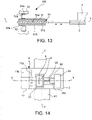
- the flat surface 24 comprises a groove 26 which, together with a slide 24a ( figure 12 ), defines the perfusion chamber 5.
- the surface of the slide 24a facing the groove 26 comprises the surface portion of the perfusion chamber 5 comprising the cytoadhesive substance, as described above.
- the cartridge for example at the slide, preferably comprises reference marks 24b, for example incisions, to facilitate the focusing of the image acquisition unit 2.
- reference marks 24b for example incisions.
- the positioning of such reference marks 24b shown in figure 12 is not indicative of the actual positioning, which will depend on the image acquisition positions which will be defined.
- the perfusion chamber 5 has an elongated shape and has a first end 5a and a second end 5b.
- the cartridge 4 further comprises, in a contiguous position to the first end 5a of the perfusion chamber 5, a well 27 for loading the blood sample.
- the well 27 has a substantially flared upward shape and comprises, at the bottom 27a, an inclined ascending microchannel 28 which opens at the first end 5a of the perfusion chamber 5.
- the perfusion chamber 5 is instead connected to an inclined descending microchannel 29 which opens into a duct 30 which in turn opens in the seat 25a of the fitting 25.
- the arrangement of the two microchannels 28, 29 with respectively ascending and descending slope optimizes the flow of the blood sample, reducing the risk of bubble formation and undesired platelet activation.
- inclined ascending microchannel or “inclined descending microchannel” indicates a microchannel having a certain inclination, straight or curvilinear, different from a step profile.
- the shear rate can be modulated by modifying the width of the perfusion chamber 5, by modifying the flow rate of the pumping system 8 or by acting on both.
- the pumping system 8 comprises, in the example described, a syringe pump 20, comprising a plunger 20a and a cylinder 20b, connected to the cartridge 4 and an actuation member 21 (shown only partially in figure 1 ) which couples the plunger 20a of the syringe pump 20 and applies a traction motion thereto indicated by the arrows of figure 3 , according to a predefined motion law and dictated by the predefined flow parameters inside the perfusion chamber 5 and on which the shear applied to the analyzed blood will depend.
- the perfusion chamber 105 has an elongated shape and comprises a first end 105a, connected with the inclined ascending microchannel 28, and a second end 105b, connected with the inclined descending microchannel 29.
- the perfusion chamber 105 is divided into two half-chambers 131, 132 by a partition 133 which has a wedge-shaped profile 134 at the first end 105a.
- the two half-chambers 131, 132 have a different width d, D, so that, by maintaining the same blood flow rate, two different shears can be obtained.
- the size of the half-chambers 131, 132 will in particular be designed so as to obtain, for a certain blood flow rate, the desired shear rates.
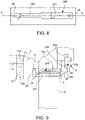
- Figure 8 shows a still different embodiment of the perfusion chamber, here indicated with the number 205.
- the perfusion chamber 205 develops along the axis A and has along said axis in series a first half-chamber 231 having width D and a second half-chamber 232 having width d different from width D.
- the half-chamber 231 having the greater width D has been placed upstream of the half-chamber 232 of smaller width d, but in a variant the two half-chambers 231, 232 can be inverted. In this case as well, by maintaining the same blood flow rate, two different shears can be obtained.
- the size of the half-chambers 231, 232 will in particular be designed so as to obtain, for a certain blood flow rate, the desired shear rates.
- FIG 10 shows still a different embodiment of the cartridge 4.
- the cartridge always comprises a body 23 closed at one end and comprising at the opposite end a fitting 25 for a syringe pump 20, which is shown already coupled to the cartridge 4 so as to form a whole.
- the cartridge 4 in this embodiment comprises a plurality of perfusion chambers 405, 405', 405".
- the centrally positioned perfusion chamber 405 has a width D which can be the same or different from one or both of the other perfusion chambers 405', 405".
- the other two perfusion chambers 405', 405" are placed on the two sides of the chamber 405 and are designed with different widths, i.e., the chamber 405' has a width D' greater than the width d" of the chamber 405".
- the two chambers 405', 405" could have equal width.
- the central perfusion chamber 405 and/or one or both of the lateral perfusion chambers 405', 405" can be divided by a partition as shown in figure 7 .
- Respective ascending microchannels 28, 28', 28" connect the well 27 with the perfusion chambers 405, 405', 405"; respective descending microchannels 29, 29', 29" connect the perfusion chambers 405, 405', 405" with the fitting 25 and thus with the syringe pump 20.
- This embodiment of a multi-chamber cartridge 4 allows the simultaneous analysis of a blood sample both in different shear conditions (by virtue of the different width of the chambers), and in relation to different types of corpuscular aggregates, obtainable by coating different portions of the slide 24a, at the chambers 405, 405', 405", with different reactive substances, as defined below.
- FIG 11 shows another embodiment of the cartridge 4.
- the cartridge always comprises a body 23 closed at one end and comprising at the opposite end a fitting 25 for a syringe pump 20, which is shown already coupled to the cartridge 4 so as to form a whole.
- the perfusion chamber 505 is divided into two half-chambers 531, 532 by a partition 533, as in the embodiment of figure 7 .
- a first half-chamber 531 has a width D greater than the width d of the second half-chamber 532.
- the two half-chambers 531, 532 can have the same width, but portions of the slide 24b can be coated at said half-chambers 531, 532 with different reactive substances, as described below.
- the perfusion chamber 505 further comprises an accumulation tank 534, placed upstream of the half-chambers 531, 532, and a collection tank 535 placed downstream of the half-chambers 531, 532.
- An inclined ascending microchannel 28 connects the well 27 with the accumulation tank 534, while the inclined descending microchannel 29 connects the collection tank 535 with the fitting 25 and thus with the syringe pump 20.
- the accumulation tank 534 and the collection tank 535 have a greater depth than the half-chambers 531, 532 and have the function of avoiding preferential lanes for the flow of blood in one of the two half-chambers 531, 532.
- the tanks 534, 535 can be omitted and the inclined ascending 28 and descending microchannels 29 can have corresponding inlet 28a and outlet 29a openings placed at the two ends of the chamber 505 at half the width D.
- the perfusion chamber 505 is placed in a transverse position, i.e., along an x axis, with respect to the y axis of the cartridge 4 which corresponds to the movement direction of the support member 3 during the analysis. This allows analyzing the corpuscular aggregates in the two half-chambers 531, 532 only by arranging a micrometric movement along the y axis, but making it unnecessary to move along the x axis of the cartridge 4 or of the image acquisition unit 2.
- the reagent movement unit 6 comprises an automatic pipettor 10.
- the automatic pipettor 10 is movable along two orthogonal axes x and z, so as to be able to move between various positions along the x axis and to be able to raise or lower the movable body 10a of the automatic pipettor 10 when necessary.
- the automatic pipettor 10 is movable between a position for withdrawing tips P at the support 11 or for withdrawing the reagents or blood sample from the respective containers C at the support 12, a position for releasing said reagents at the well 27 of the cartridge 4 and a release position of the used tips P in the tray portion 11b of the first support 11.
- the sequence of such movements includes the following steps:
- the blood sample and reagent withdrawal sequences can also be reversed.
- the positioning of the automatic pipettor 10 at the various positions occurs by means of a combined movement of the pipettor 10 along the x and z axes and of the support member 3 along the y axis.
- the withdrawal operations occur by virtue of pressure sensors associated with the free end of the movable body 10a of the automatic pipettor 10.
- the pressure sensor used in the reagent withdrawal step is adapted to detect contact with the liquid surface. This is useful because, as the analysis proceeds, the reagent tube tends to empty and thus the liquid level drops.
- the stroke of the movable body 10a along the z axis is then adjusted by means of this pressure sensor, so that the risk of not withdrawing the solution is avoided.
- the automatic pipettor 10 can be for example an automatic pipettor produced by HAMILTON LABORATORIES, mod ZEUS.
- the fluorescence image acquisition unit 2 comprises a digital image acquisition device 13, typically a CCD video camera, capable of acquiring grayscale images, so that a first series of fluorescence images can be obtained, in the form of a close-up sequence of images or video, for the formation of a platelet aggregate over time and a second series of fluorescence images for the fibrin formation over time.
- a digital image acquisition device 13 typically a CCD video camera, capable of acquiring grayscale images, so that a first series of fluorescence images can be obtained, in the form of a close-up sequence of images or video, for the formation of a platelet aggregate over time and a second series of fluorescence images for the fibrin formation over time.
- the digital image acquisition device 13 is visually connected, by means of an optical path 14, to a lens 15 which, in operating conditions, is aligned with the perfusion chamber 5 or with a selected portion thereof in which the formation of an aggregate is to be observed.
- the lens 15 is movable along the Z axis by means of an actuator (not shown).
- a first dichroic filter 16 is arranged along the optical path 14. Laterally with respect to the optical path 14 and at the first dichroic filter 16, there is a second dichroic filter 17 onto which the light radiations of a first light emitter 18 and of a second light emitter 19 converge, which emit light at predefined wavelengths, in particular for the excitation of the platelet probe and that of the fibrin.
- both the first and the second light emitters 18, 19 are LED emitters.
- first light emitter 18 and the second light emitter 19 are placed on two faces of the second dichroic filter 17 placed at 90°. It must be understood that such an arrangement is motivated by space requirements and the convenience of access to the instrumentation, so that it can be modified at will to meet different construction requirements.
- Respective band-pass filters 18a, 19a are placed between said light emitters 18, 19 and the second dichroic filter 17.
- substantially monochromatic light beams are obtained which are able to excite the fluorescent probes present in the sample under examination with the due excitation energy.
- the light emitters 18, 19 operate out of phase and preferably in stroboscopic mode so that, when the first emitter 18 emits a light beam, the second emitter 19 is off (or at zero power) and vice versa.
- the digital image acquisition device 13 can alternatively acquire an image at a first emission wavelength on a first channel and an image at a second emission wavelength on a second channel.
- the stroboscopic mode further allows to minimize the light energy delivered to the blood sample, avoiding damage thereof.
- the first excitation wavelength is about 500 nm (filtered at 480 nm) and the second excitation wavelength is about 550 nm (filtered at 546 nm), while the first emission wavelength is about 510 nm and the second emission wavelength is about 556 nm.
- the digital image acquisition unit 2 preferably is or comprises a confocal microscope.
- the image acquisition unit 2 is movable parallel to the x axis of figure 1 along a guide (not shown). This embodiment is particularly useful if using a perfusion chamber 105 ( figure 7 ) or a multi-chamber cartridge 4 ( figure 10 ) as described above.
- the acquisition unit 2 is fixed, while the cartridge 4 is movable along an x axis.
- the casing 22 containing the cartridge 4 slides along an x axis on a guide 55 placed on the support member 3 along a transverse direction (parallel to the x axis).
- micrometric movement of the casing 22 along said x axis can occur for example by means of the micrometric adjustment system 150 described in relation to figure 13 , which can be connected to an actuator 54, for example a brushless motor or the like.
- the system 150 can also be simplified, eliminating the rotating element 52 and directly coupling the fine adjustment screw 51 with the fixed element 53, by means of appropriate calibration of the respective threads.
- FIG 1 of the international application published under number WO 2006/057028 A1 An example of such a system is shown in figure 1 of the international application published under number WO 2006/057028 A1 .
- a similar micrometric adjustment system can also be adopted for the movement of the image acquisition unit 2 along the x axis.
- Figure 9 instead shows a different embodiment of the movable support member 3.
- the cartridge 4 is arranged transversely, i.e., along an x axis, and comprises a perfusion chamber 305 comprising a first half-chamber 331 and a second half-chamber 332, said half-chambers 331, 332 being placed in parallel.
- the microchannel 29 placed downstream of the perfusion chamber 305 continues in a rigid or flexible tube 234 which is arranged as a rounded elbow and ends with a fitting 225 for the cylinder 20b of the syringe pump 20. Therefore, in such an embodiment, the actuation member 21 of the syringe pump 20 is placed in an offset position with respect to the guide 41.
- this embodiment avoids the arrangement of a movement of the image acquisition unit 2 or of the cartridge 4 along an x axis.
- the acquisition of images at the two half-chambers 331, 332 can be done by means of a micrometric displacement of the support member 3 along the guide 41.
- the double half-chambers have been illustrated in relation to the performance of experiments with different shears, which requires, for the same blood flow rate, a different width of the half-chambers.
- the cartridge 4 is of the disposable type and can form a kit together with the syringe pump 20, or parts thereof, of the disposable type as well.
- the cartridge 4 and the syringe pump 20 can be in a preassembled condition.
- the syringe pump 20 can also be non-removably fastened to the fitting 25.
- the kit can further contain tubes sealed with the reagents or a tube sealed with the single reagent and optionally one or more slides 24a pretreated with the cytoadhesive substance and/or with other reactive substances, optionally in different and discrete portions of the slide 24a, and optionally comprising two or more reference marks, for example incisions.
- the slides can comprise, on the surface treated with the cytoadhesive substance, a removable protective film or they can already be coupled with the cartridge 4.
- the apparatus 1 described above can be operated automatically by a command and control unit configured to control the movement of the movable support member 3, of the movement system 6, the lens 15 and optionally the image acquisition unit 2 and/or the casing 22 of the cartridge 4 according to predefined laws of motion and to carry out the following steps:
- Step I comprises the following steps:
- Step II) comprises the following steps: IIa) Aspirating the mixture of blood and reagents or single reagent inside the perfusion channel of the cartridge by means of a syringe pump with a defined speed for a fixed time interval.
- a syringe pump with a defined speed for a fixed time interval.
- the shape of the channel or the presence of multiple channels or multiple parts of a channel can imply the creation of different shears.
- the pumping system 8 can be activated with a predefined flow rate as a function of the desired shear rate;
- Step IIb) includes focusing on the area of the perfusion chamber 5 on which the platelets adhere.
- the focusing operation of the area of the perfusion chamber 5 on which the platelets adhere is preferably carried out in autofocus mode, according to conventional procedures in the digital image acquisition field, and allows identifying the plane along the Z axis on which the adhesion of the platelets occurs.
- the acquisition area can be single or, as previously mentioned in relation to the arrangement of two or more perfusion half-chambers, multiple areas can be identified with different distances from the entry point of the blood sample in the perfusion chamber (in the case of half-chambers in sequence, fig. 8 ) or in a different position along an x axis (in the case of chambers or half-chambers in parallel, figures 7 , 9 , 10 ) or along a y axis (in the case of half-chambers in parallel with cartridge arranged transversely, fig. 11 ).
- Step IIc comprises the following operations:
- Step III comprises the following steps (such steps could be different in sequence or numerical parameter value for the series of images acquired for platelets and that acquired for fibrin):
- Lag time is an important parameter, i.e., the instant in which fibrin begins to form, with respect to t0.
- step IIIg) the integrated density ID(t) function represents a surrogate of the volume of aggregates or fibrin formed.
- step IIIh), IIIi) and IIIk the number, average size and area covered by platelet aggregates or fibrin account for the different biological dynamics of the subject's coagulation. For example, with the same % of covered area, different biological and clinical significance is associated if a small number of large area aggregates or a high number of small area aggregates are detected.
- the method of evaluating the thrombogenic potential of the single individual allows to evaluate diseases related to coagulation defects, to monitor and "adjust" the anti-aggregating or anticoagulant therapy in a personalized manner and to highlight an abnormal thrombogenic risk in patients who do not yet have pathological symptoms.
- the apparatus described above, together with the operating program of the command and control unit, allows to proceed with the performance of the evaluation method in an automatic, precise and reproducible manner, returning reliable and easily consultable analytical data.
Landscapes
- Health & Medical Sciences (AREA)
- Chemical & Material Sciences (AREA)
- Life Sciences & Earth Sciences (AREA)
- Engineering & Computer Science (AREA)
- Analytical Chemistry (AREA)
- General Health & Medical Sciences (AREA)
- Hematology (AREA)
- Biomedical Technology (AREA)
- Physics & Mathematics (AREA)
- Dispersion Chemistry (AREA)
- Biochemistry (AREA)
- General Physics & Mathematics (AREA)
- Immunology (AREA)
- Pathology (AREA)
- Clinical Laboratory Science (AREA)
- Ecology (AREA)
- Chemical Kinetics & Catalysis (AREA)
- Biophysics (AREA)
- Molecular Biology (AREA)
- Urology & Nephrology (AREA)
- Food Science & Technology (AREA)
- Medicinal Chemistry (AREA)
- Investigating Or Analysing Biological Materials (AREA)
- Investigating, Analyzing Materials By Fluorescence Or Luminescence (AREA)
Applications Claiming Priority (1)
| Application Number | Priority Date | Filing Date | Title |
|---|---|---|---|
| IT202000031577 | 2020-12-21 |
Publications (1)
| Publication Number | Publication Date |
|---|---|
| EP4016076A1 true EP4016076A1 (fr) | 2022-06-22 |
Family
ID=75111674
Family Applications (2)
| Application Number | Title | Priority Date | Filing Date |
|---|---|---|---|
| EP21206217.8A Withdrawn EP4016076A1 (fr) | 2020-12-21 | 2021-11-03 | Appareil d'évaluation de parametres sanguins |
| EP21810118.6A Pending EP4264259A1 (fr) | 2020-12-21 | 2021-11-03 | Procédé d'analyse de cellules ou de particules individuelles dans le sang par fluorescence |
Family Applications After (1)
| Application Number | Title | Priority Date | Filing Date |
|---|---|---|---|
| EP21810118.6A Pending EP4264259A1 (fr) | 2020-12-21 | 2021-11-03 | Procédé d'analyse de cellules ou de particules individuelles dans le sang par fluorescence |
Country Status (2)
| Country | Link |
|---|---|
| EP (2) | EP4016076A1 (fr) |
| WO (1) | WO2022136961A1 (fr) |
Citations (5)
| Publication number | Priority date | Publication date | Assignee | Title |
|---|---|---|---|---|
| US20040126874A1 (en) * | 2001-01-18 | 2004-07-01 | Katsuko Sakai | Cone plate type blood or the like compatibility evaluation device |
| WO2006057028A1 (fr) | 2004-11-29 | 2006-06-01 | Davide Agnetti | Dispositif permettant de deplacer des composants, notamment dans des systemes optiques |
| EP1781986A2 (fr) * | 2004-08-17 | 2007-05-09 | Immunivest Corporation | Dispositif d'imagerie diagnostique pour analyser des cellules rares circulantes |
| EP2010903A1 (fr) | 2005-12-14 | 2009-01-07 | Sedicidodici Srl | Appareil et procede destines aux diagnostic, pronostic et surveillance pharmacologique de la pathologie thrombotique-ischemique et hemorragique de l'appareil cardio-vasculaire |
| WO2013124727A2 (fr) | 2012-02-21 | 2013-08-29 | Sedicidodici Srl | Dispositif de perfusion, appareil correspondant l'utilisant et méthode permettant d'analyser la pathologie thrombotique-ischémique et hémorragique |
-
2021
- 2021-11-03 WO PCT/IB2021/060168 patent/WO2022136961A1/fr not_active Ceased
- 2021-11-03 EP EP21206217.8A patent/EP4016076A1/fr not_active Withdrawn
- 2021-11-03 EP EP21810118.6A patent/EP4264259A1/fr active Pending
Patent Citations (5)
| Publication number | Priority date | Publication date | Assignee | Title |
|---|---|---|---|---|
| US20040126874A1 (en) * | 2001-01-18 | 2004-07-01 | Katsuko Sakai | Cone plate type blood or the like compatibility evaluation device |
| EP1781986A2 (fr) * | 2004-08-17 | 2007-05-09 | Immunivest Corporation | Dispositif d'imagerie diagnostique pour analyser des cellules rares circulantes |
| WO2006057028A1 (fr) | 2004-11-29 | 2006-06-01 | Davide Agnetti | Dispositif permettant de deplacer des composants, notamment dans des systemes optiques |
| EP2010903A1 (fr) | 2005-12-14 | 2009-01-07 | Sedicidodici Srl | Appareil et procede destines aux diagnostic, pronostic et surveillance pharmacologique de la pathologie thrombotique-ischemique et hemorragique de l'appareil cardio-vasculaire |
| WO2013124727A2 (fr) | 2012-02-21 | 2013-08-29 | Sedicidodici Srl | Dispositif de perfusion, appareil correspondant l'utilisant et méthode permettant d'analyser la pathologie thrombotique-ischémique et hémorragique |
Also Published As
| Publication number | Publication date |
|---|---|
| EP4264259A1 (fr) | 2023-10-25 |
| WO2022136961A1 (fr) | 2022-06-30 |
Similar Documents
| Publication | Publication Date | Title |
|---|---|---|
| JP3547894B2 (ja) | 血液の沈降速度決定法及びその装置 | |
| US8158439B2 (en) | Multiple operating mode sample analyzer, analyzing method, and computer program product | |
| US5372946A (en) | Blood coagulation time test apparatus and method | |
| EP2875146B1 (fr) | Essai de coagulation sur petit volume | |
| US9378557B2 (en) | Microfluidic device for assessing object/test material interactions | |
| JP6105633B2 (ja) | 血栓性−虚血及び出血の病変を分析する灌流機構、および当該灌流機構を用いた装置、並びにその方法 | |
| NO895131L (no) | Fremgangsmaate for analyse av blodplatesamlinger og anordning for utfoerelse av fremgangsmaaten. | |
| McKenzie et al. | Clinical utility of available methods for determining platelet function | |
| US7687272B1 (en) | Method and apparatus for determining blood oxygen transport | |
| EP4014876A1 (fr) | Dispositif de perfusion pour l'évaluation des paramètres sanguins | |
| EP4016076A1 (fr) | Appareil d'évaluation de parametres sanguins | |
| EP4016083A1 (fr) | Méthode d'évaluation des paramètres sanguins | |
| US11998911B2 (en) | Microfluidic thromboelastometry instrument | |
| US20240402149A1 (en) | Automated, multi-parameter blood-measuring system | |
| RU123166U1 (ru) | Устройство мониторинга постранственного свертывания крови и ее компонентов | |
| WO2017093266A2 (fr) | Procédé de détermination de l'hémostase sous cisaillement | |
| WO2021108811A1 (fr) | Systèmes et procédés d'analyse hémostatique | |
| RU2727753C1 (ru) | Способ определения степени гидродинамической активации фактора фон Виллебранда и устройство для его осуществления | |
| JP2010014403A (ja) | 測定デバイス、測定装置及び測定方法 |
Legal Events
| Date | Code | Title | Description |
|---|---|---|---|
| PUAI | Public reference made under article 153(3) epc to a published international application that has entered the european phase |
Free format text: ORIGINAL CODE: 0009012 |
|
| STAA | Information on the status of an ep patent application or granted ep patent |
Free format text: STATUS: THE APPLICATION HAS BEEN PUBLISHED |
|
| AK | Designated contracting states |
Kind code of ref document: A1 Designated state(s): AL AT BE BG CH CY CZ DE DK EE ES FI FR GB GR HR HU IE IS IT LI LT LU LV MC MK MT NL NO PL PT RO RS SE SI SK SM TR |
|
| STAA | Information on the status of an ep patent application or granted ep patent |
Free format text: STATUS: THE APPLICATION IS DEEMED TO BE WITHDRAWN |
|
| 18D | Application deemed to be withdrawn |
Effective date: 20221223 |