EP4016470A1 - Procédé et dispositif de détection de repères morphologiques ou anatomiques en 3d utilisant l'apprentissage par renforcement profond - Google Patents
Procédé et dispositif de détection de repères morphologiques ou anatomiques en 3d utilisant l'apprentissage par renforcement profond Download PDFInfo
- Publication number
- EP4016470A1 EP4016470A1 EP21214467.9A EP21214467A EP4016470A1 EP 4016470 A1 EP4016470 A1 EP 4016470A1 EP 21214467 A EP21214467 A EP 21214467A EP 4016470 A1 EP4016470 A1 EP 4016470A1
- Authority
- EP
- European Patent Office
- Prior art keywords
- coordinate value
- landmark
- reinforcement learning
- deep reinforcement
- drl
- Prior art date
- Legal status (The legal status is an assumption and is not a legal conclusion. Google has not performed a legal analysis and makes no representation as to the accuracy of the status listed.)
- Pending
Links
Images

Classifications
-
- G—PHYSICS
- G06—COMPUTING OR CALCULATING; COUNTING
- G06V—IMAGE OR VIDEO RECOGNITION OR UNDERSTANDING
- G06V10/00—Arrangements for image or video recognition or understanding
- G06V10/40—Extraction of image or video features
- G06V10/44—Local feature extraction by analysis of parts of the pattern, e.g. by detecting edges, contours, loops, corners, strokes or intersections; Connectivity analysis, e.g. of connected components
-
- A—HUMAN NECESSITIES
- A61—MEDICAL OR VETERINARY SCIENCE; HYGIENE
- A61B—DIAGNOSIS; SURGERY; IDENTIFICATION
- A61B6/00—Apparatus or devices for radiation diagnosis; Apparatus or devices for radiation diagnosis combined with radiation therapy equipment
- A61B6/52—Devices using data or image processing specially adapted for radiation diagnosis
- A61B6/5211—Devices using data or image processing specially adapted for radiation diagnosis involving processing of medical diagnostic data
- A61B6/5217—Devices using data or image processing specially adapted for radiation diagnosis involving processing of medical diagnostic data extracting a diagnostic or physiological parameter from medical diagnostic data
-
- A—HUMAN NECESSITIES
- A61—MEDICAL OR VETERINARY SCIENCE; HYGIENE
- A61B—DIAGNOSIS; SURGERY; IDENTIFICATION
- A61B6/00—Apparatus or devices for radiation diagnosis; Apparatus or devices for radiation diagnosis combined with radiation therapy equipment
- A61B6/02—Arrangements for diagnosis sequentially in different planes; Stereoscopic radiation diagnosis
- A61B6/03—Computed tomography [CT]
- A61B6/032—Transmission computed tomography [CT]
-
- A—HUMAN NECESSITIES
- A61—MEDICAL OR VETERINARY SCIENCE; HYGIENE
- A61B—DIAGNOSIS; SURGERY; IDENTIFICATION
- A61B6/00—Apparatus or devices for radiation diagnosis; Apparatus or devices for radiation diagnosis combined with radiation therapy equipment
- A61B6/46—Arrangements for interfacing with the operator or the patient
- A61B6/461—Displaying means of special interest
- A61B6/466—Displaying means of special interest adapted to display 3D data
-
- A—HUMAN NECESSITIES
- A61—MEDICAL OR VETERINARY SCIENCE; HYGIENE
- A61B—DIAGNOSIS; SURGERY; IDENTIFICATION
- A61B6/00—Apparatus or devices for radiation diagnosis; Apparatus or devices for radiation diagnosis combined with radiation therapy equipment
- A61B6/50—Apparatus or devices for radiation diagnosis; Apparatus or devices for radiation diagnosis combined with radiation therapy equipment specially adapted for specific body parts; specially adapted for specific clinical applications
- A61B6/501—Apparatus or devices for radiation diagnosis; Apparatus or devices for radiation diagnosis combined with radiation therapy equipment specially adapted for specific body parts; specially adapted for specific clinical applications for diagnosis of the head, e.g. neuroimaging or craniography
-
- G—PHYSICS
- G06—COMPUTING OR CALCULATING; COUNTING
- G06T—IMAGE DATA PROCESSING OR GENERATION, IN GENERAL
- G06T15/00—Three-dimensional [3D] image rendering
- G06T15/08—Volume rendering
-
- G—PHYSICS
- G06—COMPUTING OR CALCULATING; COUNTING
- G06T—IMAGE DATA PROCESSING OR GENERATION, IN GENERAL
- G06T7/00—Image analysis
- G06T7/0002—Inspection of images, e.g. flaw detection
- G06T7/0012—Biomedical image inspection
-
- G—PHYSICS
- G16—INFORMATION AND COMMUNICATION TECHNOLOGY [ICT] SPECIALLY ADAPTED FOR SPECIFIC APPLICATION FIELDS
- G16H—HEALTHCARE INFORMATICS, i.e. INFORMATION AND COMMUNICATION TECHNOLOGY [ICT] SPECIALLY ADAPTED FOR THE HANDLING OR PROCESSING OF MEDICAL OR HEALTHCARE DATA
- G16H30/00—ICT specially adapted for the handling or processing of medical images
- G16H30/40—ICT specially adapted for the handling or processing of medical images for processing medical images, e.g. editing
-
- G—PHYSICS
- G16—INFORMATION AND COMMUNICATION TECHNOLOGY [ICT] SPECIALLY ADAPTED FOR SPECIFIC APPLICATION FIELDS
- G16H—HEALTHCARE INFORMATICS, i.e. INFORMATION AND COMMUNICATION TECHNOLOGY [ICT] SPECIALLY ADAPTED FOR THE HANDLING OR PROCESSING OF MEDICAL OR HEALTHCARE DATA
- G16H50/00—ICT specially adapted for medical diagnosis, medical simulation or medical data mining; ICT specially adapted for detecting, monitoring or modelling epidemics or pandemics
- G16H50/20—ICT specially adapted for medical diagnosis, medical simulation or medical data mining; ICT specially adapted for detecting, monitoring or modelling epidemics or pandemics for computer-aided diagnosis, e.g. based on medical expert systems
-
- G—PHYSICS
- G06—COMPUTING OR CALCULATING; COUNTING
- G06T—IMAGE DATA PROCESSING OR GENERATION, IN GENERAL
- G06T2207/00—Indexing scheme for image analysis or image enhancement
- G06T2207/10—Image acquisition modality
- G06T2207/10072—Tomographic images
- G06T2207/10081—Computed x-ray tomography [CT]
-
- G—PHYSICS
- G06—COMPUTING OR CALCULATING; COUNTING
- G06T—IMAGE DATA PROCESSING OR GENERATION, IN GENERAL
- G06T2207/00—Indexing scheme for image analysis or image enhancement
- G06T2207/20—Special algorithmic details
- G06T2207/20081—Training; Learning
-
- G—PHYSICS
- G06—COMPUTING OR CALCULATING; COUNTING
- G06V—IMAGE OR VIDEO RECOGNITION OR UNDERSTANDING
- G06V2201/00—Indexing scheme relating to image or video recognition or understanding
- G06V2201/03—Recognition of patterns in medical or anatomical images
Definitions
- the present invention relates to 3D morphological or anatomical landmark detection method and device, and more particularly, to method and device capable of accurately detecting 3D morphological or anatomical landmark based on deep reinforcement learning and volume rendering imaging.
- 3D cephalometry uses computed tomography (CT) images for measuring craniofacial morphology, and has been applied in various medical and biological fields in order to conduct treatments and/or researches on craniofacial deformity, clinical dentistry, growth, anthropology and comparative anatomy.
- CT computed tomography
- the cephalometry of 2D images has long played a central role in these applications.
- the advantages associated with accurate anatomical structure identification and complex facial structure evaluation according to recent scientific and technological developments have led to rapid adoption of 3D cephalometric analysis.
- the manual detection of landmarks on 3D data requires considerable time and expertise, and this remains a major obstacle to the widespread adoption of 3D cephalometric analysis.
- DRL deep reinforcement learning
- An object of the present invention is to provide 3D morphological or anatomical landmark detection method and device using deep reinforcement learning.
- a 3D landmark detection method may include the operations of: performing volume rendering on 3D image data to generate 3D volume rendered model data; applying a single-stage deep reinforcement learning (DRL), and/or applying a multi-stage DRL.
- the operation of applying the single-stage DRL may include the operations of: obtaining a 2D coordinate value corresponding to a landmark point on a 2D view image, which is constructed by the 3D volume rendered model data, by using a deep reinforcement learning agent; and obtaining a remaining 1D coordinate value corresponding to the landmark point based on an one-dimensional (1D) profile of the 3D image data which is obtained based on the 2D coordinate value.
- the 1D profile may be constructed of a 3D image data value on an axis perpendicular to the 2D view image and passing through a point that corresponds to the 2D coordinate value.
- the operation of applying a multi-stage DRL may include detecting the landmark point by repeating the operations of: obtaining the 2D coordinate value corresponding to the landmark point on the 2D view image, which is constructed by the 3D volume rendered model data, by using the deep reinforcement learning agent; and, from a 2D view image which is determined based on the obtained 2D coordinate value, obtaining a 2D coordinate value corresponding to the landmark point by using a deep reinforcement learning agent.
- the operation of applying the single-stage DRL or the operation of applying the multi-stage DRL may be selectively employed according to characteristics of the landmark point.
- the deep reinforcement learning agent may be trained with a deep reinforcement learning algorithm to detect a feature point corresponding to the landmark point on the 2D view image which is constructed by the 3D volume rendered model data.
- the operation of applying the single-stage DRL may include the operations of: obtaining the 2D coordinate value corresponding to the landmark point on the 2D view image, which is constructed by the 3D volume rendered model data, through the deep reinforcement learning agent; and applying a nonlinear diffusion equation to the 1D profile of the 3D image data corresponding to the remaining 1D coordinate value, and then obtaining the remaining one coordinate value based on a position with a maximum value of a first order derivative.
- the applying the multi-stage DRL may further include obtaining a first 2D coordinate value corresponding to the landmark point on a 2D projection view image, which is constructed by the 3D volume rendered model data, by using a first deep reinforcement learning agent, and obtaining a second 2D coordinate value corresponding to the landmark point on a first cut view image, which is constructed by the 3D volume rendered model data, by using a second deep reinforcement learning agent, in which the first cut view image may correspond to a plane defined by the first 2D coordinate value.
- the applying the multi-stage DRL may further include obtaining a third 2D coordinate value corresponding to the landmark point on a second cut view image, which is constructed by the 3D volume rendered model data, by using a third deep reinforcement learning agent, in which the second cut view image may correspond to a plane defined by the second 2D coordinate value.
- the 3D image data may be any one of Computed Tomography (CT), Cone Beam Computed Tomography (CBCT), Magnetic Resonance Imaging (MRI), Positron Emission Tomography (PET), and Single-Photon Emission Computed Tomography (SPECT).
- CT Computed Tomography
- CBCT Cone Beam Computed Tomography
- MRI Magnetic Resonance Imaging
- PET Positron Emission Tomography
- SPECT Single-Photon Emission Computed Tomography
- the type of landmark may be previously determined.
- the 3D image data may be acquired by capturing a patient's skull or other parts of a body.
- the 3D landmark can be efficiently and accurately detected according to the type of 3D landmark, while overcoming the complexity of 3D image data processing.
- FIG. 1 is a block diagram of a 3D anatomical landmark detection device using multi-stage deep reinforcement learning according to an embodiment of the present invention
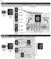
- FIG. 2 is a diagram conceptually illustrating the operation of the 3D anatomical landmark detection device using multi-stage deep reinforcement learning according to an embodiment of the present invention.
- a 3D landmark detection system may include an image acquisition device 200, an image storage device 300, and a 3D landmark detection device 100.
- the image acquisition device 200 is a device for acquiring three dimension (3D) image data of an object.
- the 3D image data may be data acquired in the form of Computed Tomography (CT), Cone Beam Computed Tomography (CBCT), Magnetic Resonance Imaging (MRI), Positron Emission Tomography (PET), Single-Photon Emission Computed Tomography (SPECT), and the like.
- CT Computed Tomography
- CBCT Cone Beam Computed Tomography
- MRI Magnetic Resonance Imaging
- PET Positron Emission Tomography
- SPECT Single-Photon Emission Computed Tomography
- the object may be a body part such as a skull and the like.
- the image storage device 300 may store 3D image data acquired by the image acquisition device 200 or provided from an external medical image information providing institution including an external medical institution or research institution.
- the 3D landmark detection device 100 may detect 3D landmark points from 3D image data provided from the image acquisition device 200 or the image storage device 300.
- the 3D landmark detection device 100 includes a data reception unit 110, a 3D volume rendered model generation unit 120, a machine learning unit 130, a single-stage DRL application unit 140, a multi-stage DRL application unit 150, a storage unit 160, a display unit 170, and a control unit 180.
- the data reception unit 110 may receive 3D image data from the image acquisition device 200 or the image storage device 300.
- the data reception unit 110 may receive DICOM format CT data from the image acquisition device 200 or the image storage device 300.
- the 3D volume rendered model generation unit 120 may perform volume rendering on 3D image data to generate 3D volume rendered model data.
- the 3D volume rendered model generation unit 120 may generate volume rendered 3D model data by using 3D visualization software library according to the following steps.
- a 2D projection image is acquired by volume rendering algorithm, and a volume rendering method specifically emphasizing bones may be applied.
- This volume rendering technique is a well-known technique for visualizing the 3D spatial dimension of a sampled function by computing a 2D projection of a color translucent volume.
- the volume rendering visualization of 3D CT data helps to recognize anatomy more clearly and to move easily between bone and soft tissue profiles.
- the latter function is a frequently performed procedure in 2D and 3D head measurements and may be useful in detecting bone and soft tissue landmarks.
- the volume rendered 3D model data may be constructed into the 2D view images.
- the 2D view images may include 2D projection view images having a view direction toward the front (anterior view), toward the back (posterior view), from above (top view), from below (bottom view), toward the left (left view), toward the right (right view), and the like.
- the volume rendered 3D model data may include a plurality of 2D cut views.
- the 2D cut view may be a view that is selectively removed to visualize internal features without completely sacrificing external context.
- the 3D volume rendered model generation unit 120 may perform voxel preprocessing by applying transparency to an uninterested region in order to find the landmark points in the cut view.
- the machine learning unit 130 may train a deep reinforcement learning agent with deep reinforcement learning algorithm to detect 2D feature points corresponding to the landmark points in the 2D view image.
- the deep reinforcement learning training is configured in such a way that the environment responds to the agent's actions, and the agent continuously acts to obtain the maximum reward from the environment, that is, to reach a position closest to the reference coordinates.
- the reinforcement learning training framework known as Double Deep Q-Network may be adopted.
- the deep reinforcement learning agent may be trained for each 2D view image with respect to each landmark point. As illustrated in TRAINING phase 2 in FIG. 2 , the deep reinforcement learning agent may be trained using a top view image for bregma. In addition, for nasion, the deep reinforcement learning agent may be trained using an anterior view image and a sagittal cut view image, respectively. Meanwhile, for the center of foramen magnum (CFM), the deep reinforcement learning agent may be trained using a sagittal cut view image and an axial cut view image, that is, with respect to two cut view images, respectively.
- CFM center of foramen magnum
- For each landmark it may be previously determined by an expert as to which of view directions will be used to train the deep reinforcement learning agent, or whether it is to be trained with only one view direction, or trained with two or more view directions, and the like.
- the single-stage DRL application unit 140 may use the deep reinforcement learning agent to detect a feature point corresponding to the landmark point on 2D view image which is constructed by the 3D volume rendered model data.
- the feature point detected in the 2D view image corresponds to two coordinate values of the 3D coordinate values of the landmark point.
- the single-stage DRL application unit 140 may use 1D profile of the 3D image data (CT data) obtained based on the 2D coordinate values previously detected in the 2D view image, to obtain the remaining one coordinate value corresponding to the landmark point and finally detect the landmark point.
- CT data 3D image data
- the 1D profile of the 3D image data is constructed of 3D image data values on an axis perpendicular to the 2D view image and passing through the feature point.
- the single-stage DRL application unit 140 may first detect the 2D coordinate values (x, y) of the feature point corresponding to the landmark in the 2D top view image using the deep reinforcement learning agent.
- the single-stage DRL application unit 140 applies the first order derivative-based boundary estimation technique to the 1D profile of the 3D image data to obtain the remaining one coordinate value (z) of the 3D coordinate values of the landmark.
- the 1D profile of the 3D image data represents a 3D image data value on an axis perpendicular to the 2D view image and passing through the feature point (x, y).
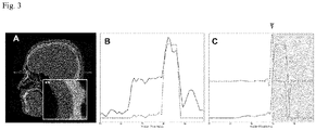
- FIG. 3 is a diagram provided to explain a first order derivative-based boundary estimation technique according to an embodiment of the present invention.
- a result of sharp gradient change of the CT value (3D image data value) at the boundary between the soft tissue and the cortical bone may be used to detect the depth of the landmark.
- the DRL algorithm may be applied to the anterior view of the skull to obtain x and z values of the 3D coordinates of the landmark.
- the 1D profile of the other CT value may be obtained along the y-axis from the feature point (x, z) through robust boundary detection using the slope values proposed below.
- the bone strength enhancement function IE(x) may be defined as in Equation 1 below.
- IE x tanh x ⁇ L W
- x is the CT value
- L is the center of the CT value range
- W is the scale value.
- FIG. 3A illustrates a cross-sectional CT image of the sagittal plane, showing a radiation beam mimic line (dashed line) passing through the detected landmark, the nasion, and a box indicated by an asterisk ( ⁇ ).
- the box indicated by an asterisk ( ⁇ ) is enlarged and shown in a larger box in the lower left side having double asterisk ( ⁇ ) and y-direction line (dashed line).
- the solid line in FIG. 3B is ID graph of the image density profile of the Hounsfield unit value along the y-axis line (corresponding to the dashed line in FIG. 3A ) passing through air, nasion, soft tissue, and bone tissue.
- the dashed line in FIG. 3B represents the bone intensity-enhanced profile.
- the solid line represents the nonlinear diffusion profile of the bone intensity-enhanced profile, and the final boundary estimation of the bone is indicated with the arrowhead and the gray area.
- the multi-stage DRL application unit 150 may detect a landmark point by repeating the operation of obtaining 2D coordinate value corresponding to the landmark point on 2D view image, which is constructed by the 3D volume rendered model data, by using the deep reinforcement learning agent.
- the multi-stage DRL application unit 150 may primarily extract the feature point corresponding to the landmark point on the 2D projection view image by using the deep reinforcement learning agent. In addition, the multi-stage DRL application unit 150 may re-extract the feature point corresponding to the landmark point by using the deep reinforcement learning agent, from a 2D cut plane view image which is newly constructed by using the 2D coordinate values of the feature point obtained from the 2D projection view image.
- the coordinate values y and z of the feature point may be obtained from the 2D side view image by using the first deep reinforcement learning agent.
- a 2D cut plane view image may be constructed, and the coordinate values x and z of the feature point may be obtained by using the second deep reinforcement learning agent.
- the storage unit 180 may store various data, programs, and the like related to the operation of the 3D landmark detection device 100.
- the storage unit 180 may be implemented as a magnetic medium such as hard disk, floppy disk, and magnetic tape, an optical medium such as CD-ROM or DVD, a magneto-optical medium such as floptical disk, and a memory device such as ROM, RAM, flash memory, and the like.
- the display unit 185 may display on the screen various types of information related to the operation of the 3D landmark detection device 100.
- the display unit 185 may be implemented as a display device such as LCD display device, LED display device, and the like.
- the control unit 190 may control the overall operation of the 3D landmark detection device 100.
- the control unit 190 detects a landmark by selectively applying one of the single-stage DRL and multi-stage DRL according to the type of landmark.
- the type of landmark may be previously determined by an expert. Depending on an embodiment, it may be automatically classified by a learned classifier or changed.
- whether to apply the single-stage DRL or the multi-stage DRL may be predetermined for each type of landmark. For those types for which sufficient accuracy is ensured with the single-stage DRL only, it may be determined to apply the single-stage DRL to avoid computational burden and complexity, and otherwise, it may be determined to apply the multi-stage DRL.
- the type of landmark may be classified by anatomical or geometrical characteristics.
- the type of landmark may be broadly classified into three types as follows.
- Type 1 may include bregma and nasion, and the landmark point may be a juxtaposition position of two or more bone tissues.
- Type 2 may include sella, anterior nasal spine, infraorbital foramen, orbital, mental foramen, and the like, and may be a landmark point on the maxima of curvature or local morphogenetic processes.
- Type 3 may include porion, center of foramen magnum, mandibular foramen, and pogonion.
- whether to apply the single-stage DRL or the multi-stage DRL may be previously determined for each landmark. This may be determined differently according to the embodiment or by the operator using the device. However, the multi-stage DRL may be applied to landmarks that do not have a landmark on the bone surface and where it is not possible to specify a corresponding landmark in the surrounding bone.
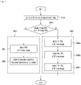
- FIG. 4 is a flowchart illustrating a 3D anatomical landmark detection method using multi-stage deep reinforcement learning according to an embodiment of the present invention.
- the 3D volume rendered model generation unit 120 may perform volume rendering on 3D image data to generate 3D volume rendered model data (S410).
- control unit 190 selects whether to apply the single-stage DRL or the multi-stage DRL according to the type of the target landmark of detection (S420).
- the single-stage DRL application unit 140 may use the deep reinforcement learning agent to detect a feature point corresponding to the landmark point on 2D view image which is constructed by the 3D volume rendered model data (S431).
- the feature point detected in the 2D view image corresponds to two coordinate values of the 3D coordinate values of the landmark point.
- the single-stage DRL application unit 140 may apply the first order derivative-based boundary estimation technique to the 1D profile of the 3D image data (CT data) obtained based on the 2D coordinate values previously detected in the 2D view image, to obtain the remaining one coordinate value corresponding to the landmark point and finally detect the landmark point (S435).
- CT data 1D profile of the 3D image data
- the 1D profile of the 3D image data is constructed of 3D image data values on an axis perpendicular to the 2D view image and passing through the feature point.
- the multi-stage DRL application unit 150 may use the first deep reinforcement learning agent to primarily extract the feature point corresponding to the landmark point on the 2D projection view image (S440a).
- the multi-stage DRL application unit 150 may use the second deep reinforcement learning agent to re-extract the feature point corresponding to the landmark point on a 2D cut plane view image which is newly constructed by using the 2D coordinate values of the feature point obtained from the 2D projection view image (S440b). As such, the multi-stage DRL application unit 150 may detect the 3D coordinate values of the landmark by using the two coordinate values of the feature point obtained in S440a and the one coordinate value obtained in S440a.
- the 3D coordinate values of the landmark may be detected as, most simply, (x 2 , y 1 , z 2 ).
- S440n the operation of obtaining the 2D coordinate value corresponding to the landmark by using the deep reinforcement learning agent is repeated from three to n times (S440n).
- the embodiments described above may be implemented as a hardware component, a software component, and/or a combination of a hardware component and a software component.
- the devices, methods, and components described in the embodiments may be implemented by using one or more general computer or specific-purpose computer such as a processor, a controller, an arithmetic logic unit (ALU), a digital signal processor, a microcomputer, a field programmable gate array (FPGA), a programmable logic unit (PLU), a microprocessor, or any other device capable of executing instructions and responding thereto.
- the processing device may execute an operating system (OS) and one or more software applications executed on the operating system. Further, the processing device may access, store, operate, process, and generate data in response to the execution of software.
- OS operating system
- the processing device may access, store, operate, process, and generate data in response to the execution of software.
- the processing device may include a plurality of processing elements and/or a plurality of types of processing elements.
- the processing device may include a plurality of processors or one processor and one controller.
- other processing configurations such as a parallel processor are possible.
- the software may include a computer program, code, instructions, or a combination of one or more of the above, and may configure the processing unit, or instruct the processing unit independently or collectively to operate as desired.
- Software and/or data may be interpreted by the processing device or, in order to provide instructions or data to the processing device, may be embodied in any type of machine, component, physical device, virtual equipment, or computer storage medium or device, permanently or temporarily.
- the software may be distributed over networked computer systems and stored or executed in a distributed manner.
- the software and data may be stored on one or more computer-readable recording media.
- the method according to the embodiments may be implemented in the form of program instructions that can be executed through various computer means and recorded in a computer-readable medium.
- the computer readable medium may include program instructions, data files, data structures, and the like alone or in combination.
- the program instructions recorded on the medium may be those specially designed and configured for the purposes of the embodiments, or may be known and available to those skilled in computer software.
- Examples of computer readable recording medium include magnetic media such as hard disks, floppy disks, and magnetic tape, optical media such as CD-ROMs and DVDs, magneto-optical media such as floptical disks, and hardware devices specifically configured to store and execute program instructions such as ROM, RAM, flash memory, and the like.
- Examples of the program instructions include machine language codes such as those generated by a compiler, as well as high-level language codes that may be executed by a computer using an interpreter, and so on.
- the hardware device described above may be configured to operate as one or more software modules in order to perform the operations according to the embodiments, and vice versa.
Landscapes
- Engineering & Computer Science (AREA)
- Health & Medical Sciences (AREA)
- Medical Informatics (AREA)
- Life Sciences & Earth Sciences (AREA)
- Public Health (AREA)
- General Health & Medical Sciences (AREA)
- Physics & Mathematics (AREA)
- Nuclear Medicine, Radiotherapy & Molecular Imaging (AREA)
- Biomedical Technology (AREA)
- Radiology & Medical Imaging (AREA)
- Pathology (AREA)
- Surgery (AREA)
- Optics & Photonics (AREA)
- Biophysics (AREA)
- Heart & Thoracic Surgery (AREA)
- Molecular Biology (AREA)
- Animal Behavior & Ethology (AREA)
- Veterinary Medicine (AREA)
- High Energy & Nuclear Physics (AREA)
- Theoretical Computer Science (AREA)
- Computer Vision & Pattern Recognition (AREA)
- General Physics & Mathematics (AREA)
- Epidemiology (AREA)
- Primary Health Care (AREA)
- Data Mining & Analysis (AREA)
- Databases & Information Systems (AREA)
- Quality & Reliability (AREA)
- Human Computer Interaction (AREA)
- Physiology (AREA)
- Pulmonology (AREA)
- Computer Graphics (AREA)
- Neurology (AREA)
- Neurosurgery (AREA)
- Dentistry (AREA)
- Oral & Maxillofacial Surgery (AREA)
- Multimedia (AREA)
- Image Analysis (AREA)
- Apparatus For Radiation Diagnosis (AREA)
Applications Claiming Priority (1)
| Application Number | Priority Date | Filing Date | Title |
|---|---|---|---|
| KR1020200177192A KR102479703B1 (ko) | 2020-12-17 | 2020-12-17 | 다단계 심층 강화학습을 이용한 3차원 형태-해부학적 기준점 검출 방법 및 장치 |
Publications (1)
| Publication Number | Publication Date |
|---|---|
| EP4016470A1 true EP4016470A1 (fr) | 2022-06-22 |
Family
ID=79024483
Family Applications (1)
| Application Number | Title | Priority Date | Filing Date |
|---|---|---|---|
| EP21214467.9A Pending EP4016470A1 (fr) | 2020-12-17 | 2021-12-14 | Procédé et dispositif de détection de repères morphologiques ou anatomiques en 3d utilisant l'apprentissage par renforcement profond |
Country Status (2)
| Country | Link |
|---|---|
| EP (1) | EP4016470A1 (fr) |
| KR (1) | KR102479703B1 (fr) |
Cited By (1)
| Publication number | Priority date | Publication date | Assignee | Title |
|---|---|---|---|---|
| CN119378695A (zh) * | 2025-01-02 | 2025-01-28 | 西安电子科技大学 | 一种时序数据反演的博弈智能体输入输出边界定位方法 |
Families Citing this family (3)
| Publication number | Priority date | Publication date | Assignee | Title |
|---|---|---|---|---|
| KR102791115B1 (ko) | 2022-12-09 | 2025-04-02 | 건양대학교 산학협력단 | 데이터 변환을 적용한 멀티 에이전트 강화학습 기반 디지털 토모신세시스 영상 노이즈 제거 시스템 |
| KR102905764B1 (ko) * | 2024-06-20 | 2025-12-31 | 주식회사 뉴큐어엠 | 다중 슬라이스 학습된 2d 확산 모델을 이용한 3d 볼륨 데이터 변환 방법, 장치 및 컴퓨터 프로그램 |
| WO2025264018A1 (fr) * | 2024-06-20 | 2025-12-26 | 주식회사 뉴큐어엠 | Procédé et dispositif de conversion de données de volume 3d utilisant un modèle de diffusion 2d entraîné par tranche multiple, et programme informatique |
Family Cites Families (4)
| Publication number | Priority date | Publication date | Assignee | Title |
|---|---|---|---|---|
| KR100837818B1 (ko) * | 2006-12-15 | 2008-06-13 | 주식회사 케이티 | 이차원 영상을 이용해 삼차원 형상을 복원하는 방법과,이를 이용한 삼차원 영상 생성 방법 |
| JP5460499B2 (ja) * | 2010-07-12 | 2014-04-02 | 日本放送協会 | 画像処理装置およびコンピュータプログラム |
| US10803612B2 (en) * | 2018-09-25 | 2020-10-13 | General Electric Company | Method and system for structure recognition in three-dimensional ultrasound data based on volume renderings |
| KR102044237B1 (ko) * | 2018-10-23 | 2019-11-13 | 연세대학교 산학협력단 | 2차원 음영 영상 기반 기계학습을 이용한 자동 3차원 랜드마크 검출 방법 및 장치 |
-
2020
- 2020-12-17 KR KR1020200177192A patent/KR102479703B1/ko active Active
-
2021
- 2021-12-14 EP EP21214467.9A patent/EP4016470A1/fr active Pending
Non-Patent Citations (2)
| Title |
|---|
| FLORIN-CRISTIAN GHESU ET AL: "Multi-Scale Deep Reinforcement Learning for Real-Time 3D-Landmark Detection in CT Scans", IEEE TRANSACTIONS ON PATTERN ANALYSIS AND MACHINE INTELLIGENCE, vol. 41, no. 1, 11 December 2017 (2017-12-11), USA, pages 176 - 189, XP055725456, ISSN: 0162-8828, DOI: 10.1109/TPAMI.2017.2782687 * |
| KUNDETI SRINIVASA RAO ET AL: "Landmark Detection in 3D Medical Images Using Reinforcement Learning", 2020 IEEE INTERNATIONAL CONFERENCE ON CLOUD COMPUTING IN EMERGING MARKETS (CCEM), IEEE, 6 November 2020 (2020-11-06), pages 42 - 46, XP033952921, DOI: 10.1109/CCEM50674.2020.00019 * |
Cited By (2)
| Publication number | Priority date | Publication date | Assignee | Title |
|---|---|---|---|---|
| CN119378695A (zh) * | 2025-01-02 | 2025-01-28 | 西安电子科技大学 | 一种时序数据反演的博弈智能体输入输出边界定位方法 |
| CN119378695B (zh) * | 2025-01-02 | 2025-06-24 | 西安电子科技大学 | 一种时序数据反演的博弈智能体输入输出边界定位方法 |
Also Published As
| Publication number | Publication date |
|---|---|
| KR102479703B1 (ko) | 2022-12-20 |
| KR20220086937A (ko) | 2022-06-24 |
Similar Documents
| Publication | Publication Date | Title |
|---|---|---|
| EP4016470A1 (fr) | Procédé et dispositif de détection de repères morphologiques ou anatomiques en 3d utilisant l'apprentissage par renforcement profond | |
| CN109074639B (zh) | 医学成像系统中的图像配准系统和方法 | |
| EP2443587B1 (fr) | Systèmes de détection de nodule pulmonaire assistée par ordinateur dans une imagerie thoracique par tomosynthèse | |
| JP6598452B2 (ja) | 医用画像処理装置及び医用画像処理方法 | |
| US9082169B2 (en) | Longitudinal monitoring of pathology | |
| EP3509013A1 (fr) | Identification d'un objet prédéfini dans un ensemble d'images d'un scanneur d'image médical pendant une procédure chirurgicale | |
| EP2620909B1 (fr) | Procédé, système et support lisible sur ordinateur pour la segmentation automatique d'une image médicale | |
| KR102271614B1 (ko) | 3차원 해부학적 기준점 검출 방법 및 장치 | |
| US10275909B2 (en) | Systems and methods for an integrated system for visualizing, simulating, modifying and 3D printing 3D objects | |
| US11715208B2 (en) | Image segmentation | |
| CN102525534A (zh) | 医用图像处理装置、医用图像处理方法 | |
| JP6458166B2 (ja) | 医用画像処理方法及び装置及びシステム及びプログラム | |
| Zeng et al. | Liver segmentation in magnetic resonance imaging via mean shape fitting with fully convolutional neural networks | |
| US9390549B2 (en) | Shape data generation method and apparatus | |
| CN111801705B (zh) | 用于加速临床工作流程的系统和方法 | |
| Jesuraj | Enhancing image segmentation process in human organs using Python | |
| US20240112331A1 (en) | Medical Image Data Processing Technique | |
| Chlebiej et al. | CT/MRI 3D Fusion for Cerebral System Analysis | |
| Zurada et al. | CT/MRI 3D Fusion for Cerebral System Analysis | |
| Paccini et al. | 3D Skin Segmentation Methods in Medical Imaging: A Comparison | |
| Kumar | A method of segmentation in 3d medical image for selection of region of interest (ROI) | |
| Skalski et al. | 3D segmentation and visualisation of mediastinal structures adjacent to tracheobronchial tree from CT data | |
| Xue | A new image quantitative method for diagnosis and therapeutic response | |
| Grandhe et al. | Fusion Based Integrated Advance Magnetic Visualization of MRI 3D Images Using Advance Matlab Tools |
Legal Events
| Date | Code | Title | Description |
|---|---|---|---|
| PUAI | Public reference made under article 153(3) epc to a published international application that has entered the european phase |
Free format text: ORIGINAL CODE: 0009012 |
|
| STAA | Information on the status of an ep patent application or granted ep patent |
Free format text: STATUS: REQUEST FOR EXAMINATION WAS MADE |
|
| 17P | Request for examination filed |
Effective date: 20211214 |
|
| AK | Designated contracting states |
Kind code of ref document: A1 Designated state(s): AL AT BE BG CH CY CZ DE DK EE ES FI FR GB GR HR HU IE IS IT LI LT LU LV MC MK MT NL NO PL PT RO RS SE SI SK SM TR |