EP4016487A1 - Dispositif et procédé de débanderolage d'une liasse banderolée de documents de valeur et système de traitement des documents de valeur - Google Patents
Dispositif et procédé de débanderolage d'une liasse banderolée de documents de valeur et système de traitement des documents de valeur Download PDFInfo
- Publication number
- EP4016487A1 EP4016487A1 EP21020590.2A EP21020590A EP4016487A1 EP 4016487 A1 EP4016487 A1 EP 4016487A1 EP 21020590 A EP21020590 A EP 21020590A EP 4016487 A1 EP4016487 A1 EP 4016487A1
- Authority
- EP
- European Patent Office
- Prior art keywords
- bundle
- banderole
- band
- holding device
- suction cup
- Prior art date
- Legal status (The legal status is an assumption and is not a legal conclusion. Google has not performed a legal analysis and makes no representation as to the accuracy of the status listed.)
- Granted
Links
Images


Classifications
-
- G—PHYSICS
- G07—CHECKING-DEVICES
- G07D—HANDLING OF COINS OR VALUABLE PAPERS, e.g. TESTING, SORTING BY DENOMINATIONS, COUNTING, DISPENSING, CHANGING OR DEPOSITING
- G07D11/00—Devices accepting coins; Devices accepting, dispensing, sorting or counting valuable papers
- G07D11/10—Mechanical details
- G07D11/16—Handling of valuable papers
-
- B—PERFORMING OPERATIONS; TRANSPORTING
- B65—CONVEYING; PACKING; STORING; HANDLING THIN OR FILAMENTARY MATERIAL
- B65B—MACHINES, APPARATUS OR DEVICES FOR, OR METHODS OF, PACKAGING ARTICLES OR MATERIALS; UNPACKING
- B65B69/00—Unpacking of articles or materials, not otherwise provided for
- B65B69/0025—Removing or cutting binding material, e.g. straps or bands
Definitions
- the invention relates to a device and a method for debanding a bundle of documents of value, in particular banknotes, provided with a band, as well as a system for processing documents of value.
- the band is generally first removed.
- devices and methods are used for this purpose, for example, in which the banderole is torn or cut open.
- This object is achieved by a device and a method for debanding a banded bundle of documents of value according to the independent claims and a system for processing documents of value with such a device.
- a first aspect of the invention relates to a device for unbanding a bundle of documents of value, in particular banknotes, provided with a band, the bundle having two opposite main sides which are formed by the top and bottom document of value of the bundle, and the band having two front side sections which on end faces formed by opposite edges of the documents of value bundles run.
- the device is characterized by a holding device, which is set up to hold at least one of the front side sections of the band, and a removal device, which is set up to act on at least one of the main sides of the bundle in order to convey the bundle out of the band, while the at least one end face section of the banderole is held by the holding device.
- the holding device is arranged in the device relative to the removal device in such a way that it can hold the band on the at least one front side section, while the removal device acts on the at least one main side of the bundle in order to convey the bundle out of the band.
- a system for processing documents of value, in particular banknotes, according to a second aspect of the invention has: a device for unbanding according to the first aspect of the invention, and at least one processing device which is set up to process, in particular to check, the documents of value of the bundle , count, sort and/or destroy.
- the processing device can in particular have a separating device which is set up to individually remove the value documents contained in the bundle conveyed out of the banderole from the bundle and set up to process, in particular to check, the individual value documents of the bundle removed from the bundle count, sort and/or destroy.
- a third aspect of the invention relates to a method for unbanding a bundle of documents of value, in particular banknotes, provided with a band, the bundle having two opposite main sides which are formed by the top and bottom document of value of the bundle, and the band having two front side sections which on from opposite Edges of the value documents run end faces of the bundle formed.
- the method is characterized in that at least one of the front side sections of the banderole is held by a holding device and at least one of the main sides of the bundle is acted upon by a removal device in order to convey the bundle out of the banderole while the at least one front side section of the banderole is being removed the holding device is held.
- aspects of the invention are preferably based on the approach of holding the banderole on the bundle in place in the area of one or both end-side sections, which run along the end faces of the bundle formed by opposite edges of the documents of value, by means of a holding device and conveying the bundle out of the banderole by a Removal device, for example a gripper or a transport device designed for transporting bundles, acts on the bundle on one or both main sides of the bundle, which are formed by the uppermost or lowermost value document, for example by the bundle being grasped, gripped or gripped on both main sides or clamped between the two main sides and then transported out of the banderole.
- a Removal device for example a gripper or a transport device designed for transporting bundles, acts on the bundle on one or both main sides of the bundle, which are formed by the uppermost or lowermost value document, for example by the bundle being grasped, gripped or gripped on both main sides or clamped between the two main sides and then transported out of the banderole.
- the removal device has a corresponding control device which controls the conveyance or transport of the bundle, in particular with the aid of the gripper or with the aid of the transport device.
- the holding device is preferably arranged in a stationary manner and/or set up to hold the banderole at a fixed location (position) and/or in a fixed position (orientation), and the removal device set up to release the gripped or clamped bundle relative to the to move the banderole held by the holding device in order to convey it out of the banderole.
- This embodiment is particularly easy to implement.
- the removal device can be stationary and the holding device can be set up to move the banderole held relative to the bundle gripped or clamped by the stationary removal device in order to convey the bundle gripped by the removal device out of the banderole or remove the banderole from the banderole pull off the bundle.
- both the holding device together with the held band and the removal device together with the gripped or clamped bundle are moved relative to one another in order to separate the band and the bundle from one another.
- the holding device is preferably set up to hold the at least one end face section of the banderole in a non-positive manner.
- the respective end face portion is by the holding device with a Normal force applied, through which a static friction force between the holding device and the end face portion is caused, which is greater than the forces occurring between the band and the bundle when conveying out the bundle, in particular frictional forces.
- a non-positive connection between the holding device and the respective front side section is easy to implement, since in particular no specially designed elements are required for a positive connection, it is easy to release and also ensures that the respective front side section of the banderole is held reliably when the bundle is pulled out .
- the holding device has at least one suction cup for this purpose.
- the holding device is set up to press the suction cup against the at least one end section of the banderole, so that the at least one end section is held by or on the suction cup.
- the suction cup can be a "passive suction cup", which preferably has a cup-shaped hollow body made of elastic material, for example silicone or rubber, which is pressed against the respective end face section, whereby a cavity surrounded by the elastic material is pressed in and the cavity contained therein Air is at least partially displaced.
- the resulting pressure of the surrounding medium, usually air, on the hollow body or the negative pressure prevailing in the cavity exerts a force by which the respective end face section is held on the suction cup.
- the use of one or more suction cups represents a particularly simple and yet reliable possibility of realizing a non-positive connection between the holding device and the respective front side section of the banderole.
- the holding device can have at least one suction cup, which has a suction interface via which it can be connected to a vacuum generating device. And the holding device can be set up to bring the suction cup into contact with the at least one end face section of the banderole.
- a vacuum generation device is also provided, which is set up to generate a negative pressure on the at least one suction cup via the suction interface, so that the at least one end face section is held by the suction cup brought into contact with the at least one end face section.
- the suction cup is preferably in the form of a cup-shaped hollow body made of an elastic material such as silicone or rubber.
- the suction interface can be formed by a hole in the region of the suction cup or hollow body facing away from the band, into which a hose end of a hose leading to the vacuum generating device can be inserted. If necessary, the intake interface can have a short piece of tubing starting at the hole. If the suction cup coupled to the activated vacuum generating device, which is also referred to as the "active suction cup" in connection with the present disclosure, comes into contact with the respective front side section of the banderole, a buildup occurs in the suction cup, in particular in the cavity of the suction cup or cup-shaped hollow body Negative pressure, from which a force results, by which the respective front side section of the banderole is held on the suction cup. In this way, a particularly reliable, detachable non-positive connection can be realized between the holding device and the respective front side section of the banderole.
- the holding device is preferably also set up to at least partially lift the at least one end face section of the banderole relative to the at least one end face of the bundle or to lift it off the at least one end face of the bundle. If the end face section of the banderole is initially in contact with at least one area of the respective end face of the bundle, the lifting of the end face section of the banderole creates a finite distance between at least a part of the end face section of the banderole and the at least one area of the end face of the bundle is produced or at least one force, in particular the normal force with which the end face section of the banderole rests on the relevant end face of the bundle, is reduced or even eliminated. In both cases, frictional forces that can occur when the bundle is pulled out of the banderole are significantly reduced in a simple and reliable manner in comparison to the end face section that was originally in contact, which makes debanding even more reliable.
- a distance created by the lifting between the at least one raised part of the front side section of the band and the at least one area of the front side of the bundle is preferably 0.2 to 2 mm, in particular 0.5 to 1.5 mm, preferably about 1 mm.
- the banderole is not damaged or torn open by such a slight lifting.
- the holding device is preferably set up to hold both end-side sections of the banderole and/or to lift them, preferably simultaneously, relative to both end-sides of the bundle.
- the banderole is held particularly reliably by the simultaneous holding or simultaneous lifting of both end-side sections and any frictional forces between the two end-side sections of the banderole on the one hand and the two end-sides of the bundle on the other hand are particularly greatly reduced, which makes unbanding even more reliable.
- the holding device preferably has at least one suction cup for each of the two front side sections of the banderole, which is set up to hold the respective front side section of the banderole in a non-positive manner and in particular to lift it relative to the respective front side of the bundle.
- the lifting preferably takes place in a direction away from the bundle, in particular by moving the respective suction cup holding the end face section in the direction away from the bundle, preferably by a distance of between 0.2 to 2 mm, for example between 0.5 to 1. 5mm
- the holding device has, in particular, a control device that controls the holding device in such a way that the at least one suction cup is brought into contact with the at least one end-side section of the banderole, and possibly also in such a way that the suction cup that has made contact with the end-side section can be used to lift the at least one end-side section the banderole is moved.
- the control device of the holding device and the control device of the removal device can communicate with one another in order to achieve the described sequence of de-banding, or be formed by a superordinate control device of the device that controls the described sequence of de-banding.
- the removal device is set up to convey the bundle provided with the banderole to the holding device.
- the bundle is preferably oriented in such a way that the main sides of the bundle formed by the uppermost and lowermost value document of the bundle are oriented vertically. This ensures that a bundle that may only be clamped on one side during transport remains oriented as horizontally as possible - due to the vertical edges - and does not bend down as a result of gravity at the non-clamped end of the bundle, which would change the position of the band.
- the main sides of the bundle can also be oriented horizontally in the holding device, in which case a corresponding horizontal stop is provided at the lower end of the holding device, which ensures that the non-clamped end of the bundle (which would otherwise bend downwards due to gravity) in the horizontal remains.
- the removal device has at least one gripper and is set up to transport the gripper, for example in a first direction, to the bundle provided with the band or to convey the bundle to the gripper, and to control the gripper located on the bundle in such a way that it clamps or grips the bundle between the two main sides and, while the at least one end-side section of the banderole is held by the holding device, the gripper, e.g a second direction opposite to the first direction, away from the band to convey the clamped bundle out of the band.
- This design represents a particularly robust and correspondingly reliable option for transporting the bundle out of the banderole that is being held.
- the removal device has at least one transport device which is set up to transport the bundle provided with the band to the holding device and, while the at least one end-side section of the band is held by the holding device, to at least one of the main sides of the bundle act to transport the bundle out of the banderole.
- the transport device is preferably set up to transport the bundle provided with the band in a transport direction towards the holding device and, while the at least one end section of the band is held by the holding device, to transport the bundle in a direction essentially identical to or opposite to the transport direction to be transported out of the banderole. In the first case, the transport direction of the bundle remains unchanged before, during and after debanding.
- the transport device is set up to transport the bundle provided with the band in a transport direction towards the holding device and, while the at least one end section of the band is held by the holding device, to transport the bundle in a direction essentially opposite to the transport direction from the to transport banderole out.
- the holding device/at least two suction cups of the holding device are located on opposite sides of a transport path on which the initially banded bundle is conveyed to the holding device, in which the banderole then preferably holds both end face sections in a non-positive manner.
- the bundle is then conveyed out of the banderole on the further transport path while the banderole is held in the holding device and, if necessary, further conveyed, for example to a separating device in which the value documents contained in the now debandered bundle are individually removed from the bundle.
- the transport of the bundle Before or for unbanding, the transport of the bundle can be temporarily stopped and/or slowed down, e.g. in order to ensure the most reliable possible frictional connection between the holding device, in particular the suction cup, and the respective front side section.
- the transport of the bundle can also be continued at an undiminished speed, in particular if the holding device is designed to be coupled sufficiently quickly to the front side sections of the band and to hold them.
- this embodiment permits continuous operation when debanding bundles; in the case of a temporary stoppage of the bundle transport, quasi-continuous operation is nevertheless possible. In all cases, not only reliable, but also particularly fast debanding of a large number of bundles is made possible.
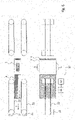
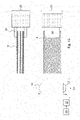
- figure 1 shows a first exemplary embodiment of a device for debanding a bundle 4 of documents of value provided with a band 1 in top view (upper area of the figure) and front view (lower area of the figure) at a first point in time.
- the documents of value are preferably banknotes.
- the essentially cuboid bundle 4 has two opposing main sides 5, which are formed by the respective top and bottom bank note of the bundle 4, and four front sides, which are formed by the respective edges of the bank notes contained in the bundle 4.
- the end faces 6 of the bundle 4 are formed by the respective longitudinal edges of the banknotes contained in the bundle 4 .
- the banderole 1 surrounding the bundle 4 has two front side sections 2, which each run on the front sides 6 of the bundle 4, and two main side sections 3, which each run on the main sides 5 of the bundle 4.
- the device has a holding device 10, shown only schematically for reasons of clarity, and a transport device 20, also shown only schematically.
- the transport device 20 has a plurality of transport units, each with two transport belts 22 circulating on transport rollers 21 .
- the transport units 21, 22 are each arranged in pairs on both sides of a transport path on which the bundle 4 is transported in the transport direction T, in that at least one of the transport rollers 21 of the transport units 21, 22 is rotated by means of a drive device (not shown) and the transport belts 22 set in motion are brought into contact with the bundle 4 .
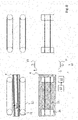
- the bundle 4, which becomes the in figure 1 illustrated first point in time is still partially outside of the transport elements 21, 22 arranged on both sides of the transport path and at the point in figure 2 illustrated second time is entirely between the transport elements 21, 22, conveyed to the holding device 10, which is based on the Figures 3 and 4 is illustrated for a third and fourth point in time.
- the holding device 10 is moved towards the two end-side sections 2 of the band 1 by means of a mechanism (not shown) (see the arrows pointing towards the band 1 in the front view of FIG figure 4 ) and a preferably non-positive connection between the holding device 10 and the front side sections 2 of the banderole 1, as in figure 5 is illustrated for a fifth point in time.
- a mechanism not shown
- the banderole 1 is held at its two front side sections 2 in the holding device 10 and is prevented from being transported further together with the bundle 4 being conveyed.
- the holding device 10 has two suction cups 11, which are pressed against the end-face sections 2 of the banderole 1 and each touch them in the region of a contact surface 2'.
- the suction cups 11 can be passive suction cups, which attach themselves to the respective end face section 2 simply by pressing on it, so that a sufficiently strong non-positive connection is established.
- the suction cups 11 can be connected via pipelines (not shown) to a vacuum generating device 12, for example a so-called ejector, by means of which a vacuum is generated at the suction cups 11 as soon as or after these are in contact with the front side sections 2 of the Banderole 1 have come into contact or to the Face sections 2 of the banderole 1 abut.
- a vacuum generating device 12 for example a so-called ejector
- the suction cups 11 in this variant are designed as active suction cups.
- the vacuum generating device 12 is preferably already activated when a bundle 4 is inserted into the device. Alternatively, however, the vacuum generating device 12 can also be activated at a later point in time, e.g. as soon as the suction cups 11 are moved towards the front side sections 2 of the banderole 1 and/or touch them.
- the suction cups 11 are preferably designed in such a way that the negative pressure and the non-positive connection resulting therefrom are essentially maintained or are reduced only very slowly when the vacuum generating device 12 is deactivated.
- a negative pressure switch 13 can be provided, by means of which the vacuum generating device 12 can be deactivated again if a negative pressure, which can preferably be predetermined, is present in the suction cups 11 or in a connecting hose.
- the suction cups 11 are designed as passive or active suction cups, it can preferably be provided that one or both of the suction cups 11 brought into contact with the front side sections 2 of the banderole 1 are moved simultaneously by a short distance, for example 0.5 mm, 1 mm or 1.5 mm to move away from bundle 4 (see those directed away from bundle 4 short arrows in the front view in figure 5 ) in order to slightly raise one or both end face sections 2 of the banderole 1 in relation to the respective end face 6 of the bundle 4 in order to reduce pressure forces and thus frictional forces between the end face sections 2 of the banderole 1 on the one hand and the respective end faces 6 of the bundle 4 on the other hand.
- a short distance for example 0.5 mm, 1 mm or 1.5 mm to move away from bundle 4 (see those directed away from bundle 4 short arrows in the front view in figure 5 ) in order to slightly raise one or both end face sections 2 of the banderole 1 in relation to the respective end face 6 of the bundle 4 in order to reduce pressure
- a front area of the bundle 4, viewed in the transport direction T, is already located between the further transport elements 21, 22 arranged on both sides of the transport path (as in figure 5 is illustrated for the fifth point in time), through which the bundle 4 is transported further in the transport direction T and thereby out of the fixed banderole 1, as shown in FIG figures 6 and 7 is illustrated for a sixth or seventh point in time.
- the further transport elements 21, 22 thus form a removal device, through which the bundle 4 is transported out of the banderole 1, in the sense of the present disclosure.
- the banderole 1 can be released or released from the holding device 10, for example by the generation and/or maintenance of the negative pressure in the suction cups 11 being stopped or interrupted. If, for example, the vacuum generating device 12 was activated while the bundle 4 was being pulled out, it can now be deactivated. If the negative pressure was maintained at the suction cups 11 while the bundle 4 was being pulled out with the vacuum generating device 12 deactivated, the negative pressure can be interrupted, for example, by venting the hoses between the suction cups 11 and the vacuum generating device 12 .
- a so-called blow-off impulse ie a blast of air through which the banderole 1 is blown away by the suction cups 11 in a jerky manner.
- a blow-off impulse ie a blast of air through which the banderole 1 is blown away by the suction cups 11 in a jerky manner.
- the banderole 1 is released from the holding device 10 so that it falls out of the holding device 10 by itself and/or is optionally output from the holding device 10 by means of an output element (not shown).
- the output element can be, for example, a hook suspended in the empty band 1 or a pin which is moved towards the released band 1 and by means of which the band 1 is ejected from the holding device 10 .
- figure 8 shows the device at an eighth point in time after the banderole 1 has fallen out of the holding device 10 or has been issued. Furthermore, the two suction cups 11 were neither moved into their starting position, which is indicated by the two arrows pointing away from the transport path.
- the debanded bundle 4 is transported further by the transport elements 21, 22, which in figure 9 is illustrated by way of example for a ninth point in time, and can be fed to further processing, for example to a separating device of a bank note processing system.
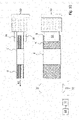
- figure 10 1 shows a second exemplary embodiment of a device for debanding a bundle 4 of documents of value provided with a band 1 in a plan view (upper area of the figure) and in a front view (lower area of the figure) at a first point in time.
- a movable gripper 30 is provided instead of the transport device 20, which has two gripper elements 31 which can grip the bundle 4 on the two main sides 5 or clamp the bundle 4 between the two main sides 5.
- the gripper 30 is coupled to a drive mechanism (not shown) by which it can be moved in a first direction R1 towards the holding device 10 in order to convey the bundle 4 to the holding device 10, as illustrated in FIG figures 11 and 12 is illustrated for a second or third point in time.
- the further transport of the bundle 4 is stopped by the gripper 30 and the holding device 10 is moved towards the two front side sections 2 of the band 1 by means of a mechanism (not shown) (see the arrows pointing towards the band 1 in the front view in figure 12 ) and a preferably non-positive connection between the holding device 10 and the front side sections 2 of the banderole 1, as in figure 13 for a fourth point in time.
- a mechanism not shown
- the banderole 1 is held in place in the holding device 10 at both of its end face sections 2 .
- the holding device 10 also has two passive or active suction cups 11 in the second exemplary embodiment shown here, which are each pressed in the area of a contact surface 2' against the front side sections 2 of the band 1, thereby creating a non-positive connection between the suction cups 11 and the Face sections 2 of the banderole 1 produce.
- the foregoing Statements in connection with the Figures 1 to 9 shown first embodiment apply accordingly to the present second embodiment.
- the gripper 30 is moved away from the holding device 10 in a second direction R2 opposite to the first direction R1, the clamped bundle 4 being pulled out of the banderole 1 held by the holding device 10, as shown in FIG figures 14 and 15 is illustrated as an example for a fifth or sixth point in time.
- the band 1 can be released or released from the holding device 10, for example by the generation and/or maintenance of the negative pressure in the suction cups 11 being stopped or interrupted, so that they falls out of the holding device 10 on its own or is optionally output from the holding device 10 by means of an output element (not shown).
- an output element not shown.
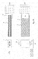
- figure 16 shows the device at a seventh point in time after the banderole 1 has fallen out of the holding device 10 or has been issued. Furthermore, the two suction cups 11 were moved back into their starting position, which is indicated by the two arrows pointing away from the transport path.
- suction cup 11 is provided for each end face section 2 of the banderole 1, it is in principle possible to provide a suction cup 11 on only one of the two end face sections 2.
- a single suction cup 11 is preferably adapted accordingly in terms of its shape and/or size and/or with regard to the level of the negative pressure generated in order to obtain a sufficiently high static friction between the suction cup 11 and the end face section 2 of the banderole 1 .
- the area of the provided suction cup 11 or the total area of the provided suction cups 11 can preferably be considered independently of the number of suction cups 11 provided in each case in order to obtain a sufficiently large static friction between the holding device 10 on the one hand and the banderole 1 on the other.
- the normal force between the suction cup 11 and the band 1 corresponds to the product of the achievable pressure difference (i.e. the negative pressure compared to the ambient pressure) and the area of the suction cup 11 or the total area in the case of two or more suction cups 11.
- the normal force is twice as high as with only one suction cup 11 per end face section 2, so that a correspondingly higher static friction is achieved.
- the shape of the suction cup 11 is selected such that it covers or contacts as large a part of the respective end face section 2 as possible.
- the respective suction cup 11 preferably has an oval shape, through which a particularly large part of the essentially rectangular area of the respective front side section 2 of the banderole can be covered or contacted.
- the surfaces of the suction cups 11 and/or the negative pressure achieved or generated with or on the suction cups 11 are preferably selected such that the sum of the forces, in particular normal forces, between the suction cups 11 and the band 1 is greater than the force between the Banderole 1 and the bundle 4. Since the normal forces caused by the negative pressure and the direction of movement of the bundle are essentially perpendicular to one another, the product of the normal force and the coefficient of friction (coefficient of friction) is preferably considered in each case. Since the coefficient of friction is essentially constant, it is advantageous to suck on the banderole 1 as firmly as possible and at the same time to have as little normal force as possible between the banderole and the bundle.
- the minimum size of the surface of the suction cup(s) 11 depends on the (normal) force required, whereas the maximum size of the surface of the suction cup(s) 11 is limited by the dimensions of the face section 2, since the suction cup 11 does not, also not minimal, must protrude beyond the respective end face section 2 in order to ensure that the negative pressure in the respective suction cup 11 is maintained.
- commercially available oval suction cups with 15 ⁇ 5 or 18 ⁇ 6 mm 2 or circular suction cups are used for the suction cups 11 .
- other sizes or formats are also possible, provided they meet the above-mentioned requirements with regard to minimum and maximum size.
- both relatively thin and relatively thick bundles 4 can be debanded with the devices according to the present disclosure.
- the suction cups 11 can be further optimized in terms of size and/or shape for particularly thin or thick bundles 4 .
- the thickness of the bundles 4 in the area of the band 1 does not vary particularly.
- the thickness of a bundle 4 with standard 100 banknotes is typically around 10 mm.
- the distance by which the suction cups 11 are moved from their initial position towards the band 1 is preferably adjustable and/or predeterminable by an operator.
- the starting position of the suction cups 11 is selected or the distance is large enough that the widest denomination of the banknotes to be processed still fits between the suction cups 11 located in the starting position.
- the suction cups 11 can be moved together mechanically to such an extent that the respective front side sections 2 of the banderole 1 can still be reliably contacted by the suction cups 11 even in the case of a bundle 4 with the narrowest denomination.
- the distance between the suction cups 11 in their initial position is at least 82 mm in order to be able to pick up a bundle of the largest denomination, with the suction cups 11 extending up to a distance of 62 mm mm or less can be moved together in order to be able to contact a bundle with the smallest denomination.
- the distance or travel path by which the suction cups 11 can be moved from their starting position towards the band 1 is therefore at least 2 ⁇ 10 mm (i.e. a total of 20 mm) for euro banknotes, preferably at least 2 ⁇ 15 mm (so a total of 30 mm).
- the speed at which the bundle 4 is conveyed out of the band 1 by means of the transport device 20 or by means of the gripper 30 can be set as a function of properties of the bundle 4 or the banknotes contained therein, preferably detected by sensors.
- Examples of preferred properties to be considered may be: thickness and/or "bulky" (i.e., non-rectangular) of the bundle, or the condition, degree of wear, limpness, or smoothness of the top and/or bottom bill of the bundle, respectively.
- bulky bundles 4 provision can be made, for example, for the speed at which the bundle is pulled out to be reduced compared to the speed at which the banded bundle 4 is transported.
- the aim is not to change the speed or only slightly to change the speed in order to pull off the band 1 more or less in passing and thereby achieve the highest possible throughput in terms of time to guarantee.
- pushing can preferably be effected by the transport units 21, 22 lying behind the bundle 4, viewed in the transport direction T, as long as the bundle 4 is still being touched by them.
- a pushing element such as a plate, a rake or pin (not shown) can be provided, through which the bundle 4 in the is pushed in the second direction R2, while the band 1 is held in the holding device 10 and the bundle 4 is pulled out of the band 1 in the second direction by means of the gripper 30.
- figure 17 shows a schematic representation of an example of a system for processing documents of value, in particular banknotes, with a device 40 for unbanding bundles 4 of banknotes, each provided with a banderole 1, according to one of the exemplary embodiments described above.
- the system also has a separating device 50 which is set up to withdraw the banknotes BN contained in the debanded bundle 4 individually from the bundle 4 .
- the individual banknotes BN are fed to a processing device 60 which is set up to process the individual banknotes BN, in particular to check, count, sort and/or destroy them.
Landscapes
- Physics & Mathematics (AREA)
- General Physics & Mathematics (AREA)
- Engineering & Computer Science (AREA)
- Mechanical Engineering (AREA)
- Basic Packing Technique (AREA)
Applications Claiming Priority (1)
| Application Number | Priority Date | Filing Date | Title |
|---|---|---|---|
| DE102020007727.7A DE102020007727A1 (de) | 2020-12-17 | 2020-12-17 | Vorrichtung und Verfahren zum Entbanderolieren eines mit einer Banderole versehenen Bündels von Wertdokumenten und System zur Bearbeitung von Wertdokumenten |
Publications (2)
| Publication Number | Publication Date |
|---|---|
| EP4016487A1 true EP4016487A1 (fr) | 2022-06-22 |
| EP4016487B1 EP4016487B1 (fr) | 2024-01-10 |
Family
ID=78789584
Family Applications (1)
| Application Number | Title | Priority Date | Filing Date |
|---|---|---|---|
| EP21020590.2A Active EP4016487B1 (fr) | 2020-12-17 | 2021-11-23 | Dispositif et procédé de débanderolage d'une liasse banderolée de documents de valeur et système de traitement des documents de valeur |
Country Status (2)
| Country | Link |
|---|---|
| EP (1) | EP4016487B1 (fr) |
| DE (1) | DE102020007727A1 (fr) |
Citations (4)
| Publication number | Priority date | Publication date | Assignee | Title |
|---|---|---|---|---|
| DE3137667A1 (de) * | 1980-09-22 | 1982-04-15 | Tokyo Shibaura Denki K.K., Kawasaki, Kanagawa | Verfahren und vorrichtung zur verarbeitung von banderolierten papierblattbuendeln |
| US4838751A (en) * | 1985-07-11 | 1989-06-13 | Tokushu Paper Manufacturing Co., Ltd. | Bale unpacking method and system therefor |
| DE4010340A1 (de) * | 1989-03-30 | 1990-10-04 | Toshiba Kawasaki Kk | Papierblatt-bearbeitungsvorrichtung |
| EP0945352A1 (fr) * | 1998-03-24 | 1999-09-29 | Kabushiki Kaisha Toshiba | Dispositif pour le traitement de bandes de liage et de papier |
Family Cites Families (2)
| Publication number | Priority date | Publication date | Assignee | Title |
|---|---|---|---|---|
| DE2729830A1 (de) | 1977-07-01 | 1979-01-11 | Gao Ges Automation Org | Verfahren zum automatischen sortieren von duennem blattgut |
| DE3229765A1 (de) | 1982-08-10 | 1984-02-16 | GAO Gesellschaft für Automation und Organisation mbH, 8000 München | Vorrichtung zum entfernen einer banderole von einem blattbuendel |
-
2020
- 2020-12-17 DE DE102020007727.7A patent/DE102020007727A1/de not_active Withdrawn
-
2021
- 2021-11-23 EP EP21020590.2A patent/EP4016487B1/fr active Active
Patent Citations (4)
| Publication number | Priority date | Publication date | Assignee | Title |
|---|---|---|---|---|
| DE3137667A1 (de) * | 1980-09-22 | 1982-04-15 | Tokyo Shibaura Denki K.K., Kawasaki, Kanagawa | Verfahren und vorrichtung zur verarbeitung von banderolierten papierblattbuendeln |
| US4838751A (en) * | 1985-07-11 | 1989-06-13 | Tokushu Paper Manufacturing Co., Ltd. | Bale unpacking method and system therefor |
| DE4010340A1 (de) * | 1989-03-30 | 1990-10-04 | Toshiba Kawasaki Kk | Papierblatt-bearbeitungsvorrichtung |
| EP0945352A1 (fr) * | 1998-03-24 | 1999-09-29 | Kabushiki Kaisha Toshiba | Dispositif pour le traitement de bandes de liage et de papier |
Also Published As
| Publication number | Publication date |
|---|---|
| EP4016487B1 (fr) | 2024-01-10 |
| DE102020007727A1 (de) | 2022-06-23 |
Similar Documents
| Publication | Publication Date | Title |
|---|---|---|
| DE102012009649B4 (de) | Greifvorrichtung | |
| EP2059445A1 (fr) | Système de magasin | |
| EP2841368A1 (fr) | Dispositif de préhension permettant de saisir des feuilles | |
| DE10047395B4 (de) | Transportsystem für flache Produkte | |
| EP1767477A1 (fr) | Procédé et appareil pour l'insertion d'articles plats dans une machine de traitement | |
| DE102013101820B4 (de) | Vorrichtung und Verfahren zum Vereinzeln von gestapelten Produkten | |
| DE102012107984B4 (de) | Verfahren zur Entnahme zusammengelegter Faltschachteln aus einer Umverpackung | |
| EP3744666A1 (fr) | Transport d'empilements de plateaux à l'aide d'une unité de désempilement | |
| EP0698573A1 (fr) | Procédé et appareil pour alimenter des marchandises en feuilles | |
| EP4016487B1 (fr) | Dispositif et procédé de débanderolage d'une liasse banderolée de documents de valeur et système de traitement des documents de valeur | |
| EP4302884B1 (fr) | Dispositif d'alignement d'objets | |
| AT411990B (de) | Leersackvereinzelung | |
| EP2994402B1 (fr) | Manipulateur | |
| EP4310033A1 (fr) | Dispositif de transport et d'orientation d'objets | |
| EP4310032A1 (fr) | Dispositif d'alignement ou de positionnement. rotation d'objets avec une surface glissante | |
| EP4299485A1 (fr) | Dispositif d'alignement ou de positionnement. rotation d'objets | |
| EP0397016B1 (fr) | Dispositif et procédé pour l'enlèvement d'une feuille séparée d'une cassette | |
| DE102010008619A1 (de) | Vorrichtung zum Vereinzeln von scheibenförmigen Elementen | |
| EP0933318A1 (fr) | Dispositif de séparation d'objects plats transportés d'une pile | |
| DE4124566C1 (fr) | ||
| DE102020116074B4 (de) | Vorrichtung und Verfahren zum Ablegen und Positionieren eines Stapelbildungshilfsmittels | |
| DE102019126657B4 (de) | Vereinzelungsvorrichtung und Verfahren zur Vereinzelung von dünnen Blatteinheiten aus einem Blattstapel durch eine Vereinzelungsvorrichtung | |
| WO2012139773A2 (fr) | Dispositif et procédé pour déposer des produits en forme de feuille | |
| DE19930819A1 (de) | Vorrichtung zum Vereinzeln und Zuführen von Bogen | |
| DE102018133454B4 (de) | Verfahren zum Stapeln wenigstens eines Mediums, sowie Stapelsystem |
Legal Events
| Date | Code | Title | Description |
|---|---|---|---|
| PUAI | Public reference made under article 153(3) epc to a published international application that has entered the european phase |
Free format text: ORIGINAL CODE: 0009012 |
|
| STAA | Information on the status of an ep patent application or granted ep patent |
Free format text: STATUS: THE APPLICATION HAS BEEN PUBLISHED |
|
| AK | Designated contracting states |
Kind code of ref document: A1 Designated state(s): AL AT BE BG CH CY CZ DE DK EE ES FI FR GB GR HR HU IE IS IT LI LT LU LV MC MK MT NL NO PL PT RO RS SE SI SK SM TR |
|
| STAA | Information on the status of an ep patent application or granted ep patent |
Free format text: STATUS: REQUEST FOR EXAMINATION WAS MADE |
|
| 17P | Request for examination filed |
Effective date: 20221222 |
|
| RBV | Designated contracting states (corrected) |
Designated state(s): AL AT BE BG CH CY CZ DE DK EE ES FI FR GB GR HR HU IE IS IT LI LT LU LV MC MK MT NL NO PL PT RO RS SE SI SK SM TR |
|
| RAP3 | Party data changed (applicant data changed or rights of an application transferred) |
Owner name: GIESECKE+DEVRIENT CURRENCY TECHNOLOGY GMBH |
|
| P01 | Opt-out of the competence of the unified patent court (upc) registered |
Effective date: 20230519 |
|
| GRAP | Despatch of communication of intention to grant a patent |
Free format text: ORIGINAL CODE: EPIDOSNIGR1 |
|
| STAA | Information on the status of an ep patent application or granted ep patent |
Free format text: STATUS: GRANT OF PATENT IS INTENDED |
|
| INTG | Intention to grant announced |
Effective date: 20230926 |
|
| GRAS | Grant fee paid |
Free format text: ORIGINAL CODE: EPIDOSNIGR3 |
|
| GRAA | (expected) grant |
Free format text: ORIGINAL CODE: 0009210 |
|
| STAA | Information on the status of an ep patent application or granted ep patent |
Free format text: STATUS: THE PATENT HAS BEEN GRANTED |
|
| AK | Designated contracting states |
Kind code of ref document: B1 Designated state(s): AL AT BE BG CH CY CZ DE DK EE ES FI FR GB GR HR HU IE IS IT LI LT LU LV MC MK MT NL NO PL PT RO RS SE SI SK SM TR |
|
| REG | Reference to a national code |
Ref country code: GB Ref legal event code: FG4D Free format text: NOT ENGLISH |
|
| REG | Reference to a national code |
Ref country code: CH Ref legal event code: EP |
|
| REG | Reference to a national code |
Ref country code: DE Ref legal event code: R096 Ref document number: 502021002387 Country of ref document: DE |
|
| REG | Reference to a national code |
Ref country code: IE Ref legal event code: FG4D Free format text: LANGUAGE OF EP DOCUMENT: GERMAN |
|
| REG | Reference to a national code |
Ref country code: LT Ref legal event code: MG9D |
|
| REG | Reference to a national code |
Ref country code: NL Ref legal event code: MP Effective date: 20240110 |
|
| PG25 | Lapsed in a contracting state [announced via postgrant information from national office to epo] |
Ref country code: NL Free format text: LAPSE BECAUSE OF FAILURE TO SUBMIT A TRANSLATION OF THE DESCRIPTION OR TO PAY THE FEE WITHIN THE PRESCRIBED TIME-LIMIT Effective date: 20240110 |
|
| PG25 | Lapsed in a contracting state [announced via postgrant information from national office to epo] |
Ref country code: NL Free format text: LAPSE BECAUSE OF FAILURE TO SUBMIT A TRANSLATION OF THE DESCRIPTION OR TO PAY THE FEE WITHIN THE PRESCRIBED TIME-LIMIT Effective date: 20240110 |
|
| PG25 | Lapsed in a contracting state [announced via postgrant information from national office to epo] |
Ref country code: IS Free format text: LAPSE BECAUSE OF FAILURE TO SUBMIT A TRANSLATION OF THE DESCRIPTION OR TO PAY THE FEE WITHIN THE PRESCRIBED TIME-LIMIT Effective date: 20240510 |
|
| PG25 | Lapsed in a contracting state [announced via postgrant information from national office to epo] |
Ref country code: LT Free format text: LAPSE BECAUSE OF FAILURE TO SUBMIT A TRANSLATION OF THE DESCRIPTION OR TO PAY THE FEE WITHIN THE PRESCRIBED TIME-LIMIT Effective date: 20240110 |
|
| PG25 | Lapsed in a contracting state [announced via postgrant information from national office to epo] |
Ref country code: GR Free format text: LAPSE BECAUSE OF FAILURE TO SUBMIT A TRANSLATION OF THE DESCRIPTION OR TO PAY THE FEE WITHIN THE PRESCRIBED TIME-LIMIT Effective date: 20240411 |
|
| PG25 | Lapsed in a contracting state [announced via postgrant information from national office to epo] |
Ref country code: RS Free format text: LAPSE BECAUSE OF FAILURE TO SUBMIT A TRANSLATION OF THE DESCRIPTION OR TO PAY THE FEE WITHIN THE PRESCRIBED TIME-LIMIT Effective date: 20240410 Ref country code: HR Free format text: LAPSE BECAUSE OF FAILURE TO SUBMIT A TRANSLATION OF THE DESCRIPTION OR TO PAY THE FEE WITHIN THE PRESCRIBED TIME-LIMIT Effective date: 20240110 |
|
| PG25 | Lapsed in a contracting state [announced via postgrant information from national office to epo] |
Ref country code: ES Free format text: LAPSE BECAUSE OF FAILURE TO SUBMIT A TRANSLATION OF THE DESCRIPTION OR TO PAY THE FEE WITHIN THE PRESCRIBED TIME-LIMIT Effective date: 20240110 |
|
| PG25 | Lapsed in a contracting state [announced via postgrant information from national office to epo] |
Ref country code: RS Free format text: LAPSE BECAUSE OF FAILURE TO SUBMIT A TRANSLATION OF THE DESCRIPTION OR TO PAY THE FEE WITHIN THE PRESCRIBED TIME-LIMIT Effective date: 20240410 Ref country code: NO Free format text: LAPSE BECAUSE OF FAILURE TO SUBMIT A TRANSLATION OF THE DESCRIPTION OR TO PAY THE FEE WITHIN THE PRESCRIBED TIME-LIMIT Effective date: 20240410 Ref country code: LT Free format text: LAPSE BECAUSE OF FAILURE TO SUBMIT A TRANSLATION OF THE DESCRIPTION OR TO PAY THE FEE WITHIN THE PRESCRIBED TIME-LIMIT Effective date: 20240110 Ref country code: IS Free format text: LAPSE BECAUSE OF FAILURE TO SUBMIT A TRANSLATION OF THE DESCRIPTION OR TO PAY THE FEE WITHIN THE PRESCRIBED TIME-LIMIT Effective date: 20240510 Ref country code: HR Free format text: LAPSE BECAUSE OF FAILURE TO SUBMIT A TRANSLATION OF THE DESCRIPTION OR TO PAY THE FEE WITHIN THE PRESCRIBED TIME-LIMIT Effective date: 20240110 Ref country code: GR Free format text: LAPSE BECAUSE OF FAILURE TO SUBMIT A TRANSLATION OF THE DESCRIPTION OR TO PAY THE FEE WITHIN THE PRESCRIBED TIME-LIMIT Effective date: 20240411 Ref country code: ES Free format text: LAPSE BECAUSE OF FAILURE TO SUBMIT A TRANSLATION OF THE DESCRIPTION OR TO PAY THE FEE WITHIN THE PRESCRIBED TIME-LIMIT Effective date: 20240110 Ref country code: BG Free format text: LAPSE BECAUSE OF FAILURE TO SUBMIT A TRANSLATION OF THE DESCRIPTION OR TO PAY THE FEE WITHIN THE PRESCRIBED TIME-LIMIT Effective date: 20240110 |
|
| PG25 | Lapsed in a contracting state [announced via postgrant information from national office to epo] |
Ref country code: PL Free format text: LAPSE BECAUSE OF FAILURE TO SUBMIT A TRANSLATION OF THE DESCRIPTION OR TO PAY THE FEE WITHIN THE PRESCRIBED TIME-LIMIT Effective date: 20240110 Ref country code: PT Free format text: LAPSE BECAUSE OF FAILURE TO SUBMIT A TRANSLATION OF THE DESCRIPTION OR TO PAY THE FEE WITHIN THE PRESCRIBED TIME-LIMIT Effective date: 20240510 |
|
| PG25 | Lapsed in a contracting state [announced via postgrant information from national office to epo] |
Ref country code: SE Free format text: LAPSE BECAUSE OF FAILURE TO SUBMIT A TRANSLATION OF THE DESCRIPTION OR TO PAY THE FEE WITHIN THE PRESCRIBED TIME-LIMIT Effective date: 20240110 Ref country code: PT Free format text: LAPSE BECAUSE OF FAILURE TO SUBMIT A TRANSLATION OF THE DESCRIPTION OR TO PAY THE FEE WITHIN THE PRESCRIBED TIME-LIMIT Effective date: 20240510 Ref country code: PL Free format text: LAPSE BECAUSE OF FAILURE TO SUBMIT A TRANSLATION OF THE DESCRIPTION OR TO PAY THE FEE WITHIN THE PRESCRIBED TIME-LIMIT Effective date: 20240110 Ref country code: LV Free format text: LAPSE BECAUSE OF FAILURE TO SUBMIT A TRANSLATION OF THE DESCRIPTION OR TO PAY THE FEE WITHIN THE PRESCRIBED TIME-LIMIT Effective date: 20240110 |
|
| PG25 | Lapsed in a contracting state [announced via postgrant information from national office to epo] |
Ref country code: DK Free format text: LAPSE BECAUSE OF FAILURE TO SUBMIT A TRANSLATION OF THE DESCRIPTION OR TO PAY THE FEE WITHIN THE PRESCRIBED TIME-LIMIT Effective date: 20240110 |
|
| REG | Reference to a national code |
Ref country code: DE Ref legal event code: R097 Ref document number: 502021002387 Country of ref document: DE |
|
| PG25 | Lapsed in a contracting state [announced via postgrant information from national office to epo] |
Ref country code: SM Free format text: LAPSE BECAUSE OF FAILURE TO SUBMIT A TRANSLATION OF THE DESCRIPTION OR TO PAY THE FEE WITHIN THE PRESCRIBED TIME-LIMIT Effective date: 20240110 |
|
| PG25 | Lapsed in a contracting state [announced via postgrant information from national office to epo] |
Ref country code: EE Free format text: LAPSE BECAUSE OF FAILURE TO SUBMIT A TRANSLATION OF THE DESCRIPTION OR TO PAY THE FEE WITHIN THE PRESCRIBED TIME-LIMIT Effective date: 20240110 Ref country code: CZ Free format text: LAPSE BECAUSE OF FAILURE TO SUBMIT A TRANSLATION OF THE DESCRIPTION OR TO PAY THE FEE WITHIN THE PRESCRIBED TIME-LIMIT Effective date: 20240110 |
|
| PG25 | Lapsed in a contracting state [announced via postgrant information from national office to epo] |
Ref country code: SK Free format text: LAPSE BECAUSE OF FAILURE TO SUBMIT A TRANSLATION OF THE DESCRIPTION OR TO PAY THE FEE WITHIN THE PRESCRIBED TIME-LIMIT Effective date: 20240110 |
|
| PG25 | Lapsed in a contracting state [announced via postgrant information from national office to epo] |
Ref country code: SM Free format text: LAPSE BECAUSE OF FAILURE TO SUBMIT A TRANSLATION OF THE DESCRIPTION OR TO PAY THE FEE WITHIN THE PRESCRIBED TIME-LIMIT Effective date: 20240110 Ref country code: SK Free format text: LAPSE BECAUSE OF FAILURE TO SUBMIT A TRANSLATION OF THE DESCRIPTION OR TO PAY THE FEE WITHIN THE PRESCRIBED TIME-LIMIT Effective date: 20240110 Ref country code: RO Free format text: LAPSE BECAUSE OF FAILURE TO SUBMIT A TRANSLATION OF THE DESCRIPTION OR TO PAY THE FEE WITHIN THE PRESCRIBED TIME-LIMIT Effective date: 20240110 Ref country code: EE Free format text: LAPSE BECAUSE OF FAILURE TO SUBMIT A TRANSLATION OF THE DESCRIPTION OR TO PAY THE FEE WITHIN THE PRESCRIBED TIME-LIMIT Effective date: 20240110 Ref country code: DK Free format text: LAPSE BECAUSE OF FAILURE TO SUBMIT A TRANSLATION OF THE DESCRIPTION OR TO PAY THE FEE WITHIN THE PRESCRIBED TIME-LIMIT Effective date: 20240110 Ref country code: CZ Free format text: LAPSE BECAUSE OF FAILURE TO SUBMIT A TRANSLATION OF THE DESCRIPTION OR TO PAY THE FEE WITHIN THE PRESCRIBED TIME-LIMIT Effective date: 20240110 |
|
| PLBE | No opposition filed within time limit |
Free format text: ORIGINAL CODE: 0009261 |
|
| STAA | Information on the status of an ep patent application or granted ep patent |
Free format text: STATUS: NO OPPOSITION FILED WITHIN TIME LIMIT |
|
| PG25 | Lapsed in a contracting state [announced via postgrant information from national office to epo] |
Ref country code: IT Free format text: LAPSE BECAUSE OF FAILURE TO SUBMIT A TRANSLATION OF THE DESCRIPTION OR TO PAY THE FEE WITHIN THE PRESCRIBED TIME-LIMIT Effective date: 20240110 |
|
| 26N | No opposition filed |
Effective date: 20241011 |
|
| PG25 | Lapsed in a contracting state [announced via postgrant information from national office to epo] |
Ref country code: IT Free format text: LAPSE BECAUSE OF FAILURE TO SUBMIT A TRANSLATION OF THE DESCRIPTION OR TO PAY THE FEE WITHIN THE PRESCRIBED TIME-LIMIT Effective date: 20240110 |
|
| PG25 | Lapsed in a contracting state [announced via postgrant information from national office to epo] |
Ref country code: SI Free format text: LAPSE BECAUSE OF FAILURE TO SUBMIT A TRANSLATION OF THE DESCRIPTION OR TO PAY THE FEE WITHIN THE PRESCRIBED TIME-LIMIT Effective date: 20240110 |
|
| PG25 | Lapsed in a contracting state [announced via postgrant information from national office to epo] |
Ref country code: MC Free format text: LAPSE BECAUSE OF FAILURE TO SUBMIT A TRANSLATION OF THE DESCRIPTION OR TO PAY THE FEE WITHIN THE PRESCRIBED TIME-LIMIT Effective date: 20240110 |
|
| PG25 | Lapsed in a contracting state [announced via postgrant information from national office to epo] |
Ref country code: LU Free format text: LAPSE BECAUSE OF NON-PAYMENT OF DUE FEES Effective date: 20241123 |
|
| REG | Reference to a national code |
Ref country code: BE Ref legal event code: MM Effective date: 20241130 |
|
| PG25 | Lapsed in a contracting state [announced via postgrant information from national office to epo] |
Ref country code: FI Free format text: LAPSE BECAUSE OF FAILURE TO SUBMIT A TRANSLATION OF THE DESCRIPTION OR TO PAY THE FEE WITHIN THE PRESCRIBED TIME-LIMIT Effective date: 20240110 |
|
| PG25 | Lapsed in a contracting state [announced via postgrant information from national office to epo] |
Ref country code: BE Free format text: LAPSE BECAUSE OF NON-PAYMENT OF DUE FEES Effective date: 20241130 |
|
| PG25 | Lapsed in a contracting state [announced via postgrant information from national office to epo] |
Ref country code: IE Free format text: LAPSE BECAUSE OF NON-PAYMENT OF DUE FEES Effective date: 20241123 |
|
| REG | Reference to a national code |
Ref country code: CH Ref legal event code: U11 Free format text: ST27 STATUS EVENT CODE: U-0-0-U10-U11 (AS PROVIDED BY THE NATIONAL OFFICE) Effective date: 20251201 |
|
| PGFP | Annual fee paid to national office [announced via postgrant information from national office to epo] |
Ref country code: DE Payment date: 20251118 Year of fee payment: 5 |
|
| PGFP | Annual fee paid to national office [announced via postgrant information from national office to epo] |
Ref country code: GB Payment date: 20251120 Year of fee payment: 5 |
|
| PGFP | Annual fee paid to national office [announced via postgrant information from national office to epo] |
Ref country code: AT Payment date: 20260113 Year of fee payment: 5 |
|
| PGFP | Annual fee paid to national office [announced via postgrant information from national office to epo] |
Ref country code: FR Payment date: 20251120 Year of fee payment: 5 |
|
| PGFP | Annual fee paid to national office [announced via postgrant information from national office to epo] |
Ref country code: CH Payment date: 20251201 Year of fee payment: 5 |
|
| PG25 | Lapsed in a contracting state [announced via postgrant information from national office to epo] |
Ref country code: HU Free format text: LAPSE BECAUSE OF FAILURE TO SUBMIT A TRANSLATION OF THE DESCRIPTION OR TO PAY THE FEE WITHIN THE PRESCRIBED TIME-LIMIT; INVALID AB INITIO Effective date: 20211123 |
|
| PG25 | Lapsed in a contracting state [announced via postgrant information from national office to epo] |
Ref country code: CY Free format text: LAPSE BECAUSE OF FAILURE TO SUBMIT A TRANSLATION OF THE DESCRIPTION OR TO PAY THE FEE WITHIN THE PRESCRIBED TIME-LIMIT; INVALID AB INITIO Effective date: 20211123 |