EP4016565A1 - Transformateur de courant - Google Patents
Transformateur de courant Download PDFInfo
- Publication number
- EP4016565A1 EP4016565A1 EP21204382.2A EP21204382A EP4016565A1 EP 4016565 A1 EP4016565 A1 EP 4016565A1 EP 21204382 A EP21204382 A EP 21204382A EP 4016565 A1 EP4016565 A1 EP 4016565A1
- Authority
- EP
- European Patent Office
- Prior art keywords
- magnetic core
- core structure
- magnetic
- side winding
- primary
- Prior art date
- Legal status (The legal status is an assumption and is not a legal conclusion. Google has not performed a legal analysis and makes no representation as to the accuracy of the status listed.)
- Pending
Links
- 238000004804 winding Methods 0.000 claims abstract description 261
- 238000001514 detection method Methods 0.000 claims description 9
- 230000004907 flux Effects 0.000 abstract description 129
- 238000010586 diagram Methods 0.000 description 17
- 230000035699 permeability Effects 0.000 description 7
- 239000000696 magnetic material Substances 0.000 description 3
- 238000000034 method Methods 0.000 description 3
- 238000010248 power generation Methods 0.000 description 3
- XEEYBQQBJWHFJM-UHFFFAOYSA-N Iron Chemical compound [Fe] XEEYBQQBJWHFJM-UHFFFAOYSA-N 0.000 description 2
- 229910000976 Electrical steel Inorganic materials 0.000 description 1
- 238000005452 bending Methods 0.000 description 1
- 230000005540 biological transmission Effects 0.000 description 1
- 238000009413 insulation Methods 0.000 description 1
- 229910052742 iron Inorganic materials 0.000 description 1
- 229910001004 magnetic alloy Inorganic materials 0.000 description 1
- 239000000463 material Substances 0.000 description 1
- 230000001629 suppression Effects 0.000 description 1
- 229910000859 α-Fe Inorganic materials 0.000 description 1
Images


Classifications
-
- H—ELECTRICITY
- H01—ELECTRIC ELEMENTS
- H01F—MAGNETS; INDUCTANCES; TRANSFORMERS; SELECTION OF MATERIALS FOR THEIR MAGNETIC PROPERTIES
- H01F27/00—Details of transformers or inductances, in general
- H01F27/28—Coils; Windings; Conductive connections
- H01F27/2823—Wires
-
- H—ELECTRICITY
- H01—ELECTRIC ELEMENTS
- H01F—MAGNETS; INDUCTANCES; TRANSFORMERS; SELECTION OF MATERIALS FOR THEIR MAGNETIC PROPERTIES
- H01F38/00—Adaptations of transformers or inductances for specific applications or functions
- H01F38/20—Instruments transformers
- H01F38/22—Instruments transformers for single phase AC
- H01F38/28—Current transformers
- H01F38/30—Constructions
-
- G—PHYSICS
- G01—MEASURING; TESTING
- G01R—MEASURING ELECTRIC VARIABLES; MEASURING MAGNETIC VARIABLES
- G01R15/00—Details of measuring arrangements of the types provided for in groups G01R17/00 - G01R29/00, G01R33/00 - G01R33/26 or G01R35/00
- G01R15/14—Adaptations providing voltage or current isolation, e.g. for high-voltage or high-current networks
- G01R15/18—Adaptations providing voltage or current isolation, e.g. for high-voltage or high-current networks using inductive devices, e.g. transformers
- G01R15/183—Adaptations providing voltage or current isolation, e.g. for high-voltage or high-current networks using inductive devices, e.g. transformers using transformers with a magnetic core
-
- H—ELECTRICITY
- H01—ELECTRIC ELEMENTS
- H01F—MAGNETS; INDUCTANCES; TRANSFORMERS; SELECTION OF MATERIALS FOR THEIR MAGNETIC PROPERTIES
- H01F27/00—Details of transformers or inductances, in general
- H01F27/24—Magnetic cores
-
- H—ELECTRICITY
- H01—ELECTRIC ELEMENTS
- H01F—MAGNETS; INDUCTANCES; TRANSFORMERS; SELECTION OF MATERIALS FOR THEIR MAGNETIC PROPERTIES
- H01F27/00—Details of transformers or inductances, in general
- H01F27/28—Coils; Windings; Conductive connections
-
- H—ELECTRICITY
- H01—ELECTRIC ELEMENTS
- H01F—MAGNETS; INDUCTANCES; TRANSFORMERS; SELECTION OF MATERIALS FOR THEIR MAGNETIC PROPERTIES
- H01F27/00—Details of transformers or inductances, in general
- H01F27/28—Coils; Windings; Conductive connections
- H01F27/2895—Windings disposed upon ring cores
-
- H—ELECTRICITY
- H01—ELECTRIC ELEMENTS
- H01F—MAGNETS; INDUCTANCES; TRANSFORMERS; SELECTION OF MATERIALS FOR THEIR MAGNETIC PROPERTIES
- H01F27/00—Details of transformers or inductances, in general
- H01F27/28—Coils; Windings; Conductive connections
- H01F27/30—Fastening or clamping coils, windings, or parts thereof together; Fastening or mounting coils or windings on core, casing, or other support
- H01F27/306—Fastening or mounting coils or windings on core, casing or other support
-
- H—ELECTRICITY
- H01—ELECTRIC ELEMENTS
- H01F—MAGNETS; INDUCTANCES; TRANSFORMERS; SELECTION OF MATERIALS FOR THEIR MAGNETIC PROPERTIES
- H01F38/00—Adaptations of transformers or inductances for specific applications or functions
- H01F38/20—Instruments transformers
- H01F38/22—Instruments transformers for single phase AC
- H01F38/28—Current transformers
- H01F38/30—Constructions
- H01F2038/305—Constructions with toroidal magnetic core
Definitions
- This application relates to an electronic element, and in particular, to a current transformer.
- a photovoltaic power generation system is a power generating system that directly converts solar energy into electric energy by using a solar cell. Direct current arcing may occur in a process of generating power by using the photovoltaic power generation system.
- an arcing detection apparatus Arc-fault circuit interrupter, AFCI
- AFCI arc-fault circuit interrupter
- a primary-side winding of a current transformer is serially connected to a power line on which a current needs to be measured, and a current that flows through the primary-side winding may be determined based on a detected current that flows through a secondary-side winding of the current transformer, and further the current that needs to be measured is determined.
- the current transformer may be configured to detect a differential mode current and a common mode current in the power line.
- This application provides a current transformer with a simple structure, so that a differential-mode-current signal and a common-mode-current signal can be accurately collected, to independently measure a differential mode current and a common mode current.
- an embodiment of this application provides a current transformer applicable to an arcing detection apparatus.
- the current transformer is configured to detect a differential-mode-current signal.
- the current transformer includes a magnetic core, a first primary-side winding, a second primary-side winding, and a first secondary-side winding.
- the magnetic core includes a first closed magnetic circuit and a second closed magnetic circuit.
- the first closed magnetic circuit is formed by connecting a first magnetic core structure and a second magnetic core structure
- the second closed magnetic circuit is formed by connecting the first magnetic core structure and a third magnetic core structure
- the first magnetic core structure is a magnetic core structure common to the first closed magnetic circuit and the second closed magnetic circuit.
- the first primary-side winding passes through the first closed magnetic circuit
- the second primary-side winding passes through the second closed magnetic circuit.
- the first secondary-side winding is wound around the first magnetic core structure.
- the current transformer When the current transformer is connected to a circuit to detect a differential mode current in the circuit, if a first current that flows through the first primary-side winding and a second current that flows through the second primary-side winding are differential mode currents, a first magnetic flux and a second magnetic flux are superimposed; or if the first current that flows through the first primary-side winding and the second current that flows through the second primary-side winding are common mode currents, the first magnetic flux and the second magnetic flux cancel each other out.
- the first magnetic flux is a magnetic flux that is generated in the first magnetic core structure when the first current passes through the first primary-side winding
- the second magnetic flux is a magnetic flux that is generated in the first magnetic core structure when the second current passes through the second primary-side winding.
- the first primary-side winding and the second primary-side winding may be respectively serially connected to two lines on which the differential mode currents need to be measured.
- the first current that flows through the first primary-side winding and the second current that flows through the second primary-side winding are differential mode currents
- a positive direction of the first magnetic flux generated by the first current in the first magnetic core structure is the same as a positive direction of the second magnetic flux generated by the second current in the first magnetic core structure, and the first magnetic flux and the second magnetic flux are superimposed, to increase magnetic fluxes generated by the differential mode currents.
- a positive direction of the first magnetic flux generated by the first current in the first magnetic core structure is opposite to a positive direction of the second magnetic flux generated by the second current in the first magnetic core structure, and the first magnetic flux and the second magnetic flux cancel each other out, to suppress magnetic fluxes generated by the common mode currents.
- magnetic fluxes in the first magnetic core structure are mainly the magnetic fluxes generated by the differential mode currents.
- a change of a magnetic flux in the first magnetic core structure enables the first secondary-side winding wound around the first magnetic core structure to generate an induced current. Therefore, a current output by the first secondary-side winding may be used to feed back the differential mode current.
- the second magnetic core structure may be a "U"-shaped magnetic core structure, an arc-shaped magnetic core structure, an angle-shaped magnetic core structure, or the like.
- the third magnetic core structure may be a "U"-shaped magnetic core structure, an arc-shaped magnetic core structure, an angle-shaped magnetic core structure, or the like.
- a shape and a size of the second magnetic core structure and a shape and a size of the third magnetic core structure are not limited in this application.
- the second magnetic core structure and the third magnetic core structure are magnetic core structures symmetric to each other, and the second magnetic core structure and the third magnetic core structure have a same size and a same shape.
- the second magnetic core structure and the third magnetic core structure have a same magnetic resistance, and both the second magnetic core structure and the third magnetic core structure have a comparatively small magnetic resistance.
- the current transformer may further include a second secondary-side winding.
- a first winding of the second secondary-side winding is wound around the second magnetic core structure, and a second winding of the second secondary-side winding is wound around the third magnetic core structure.
- the first winding of the second secondary-side winding and the second winding of the second secondary-side winding are serially connected.
- a positive direction of a third magnetic flux generated by the first current in the second magnetic core structure and the third magnetic core structure is opposite to a positive direction of a fourth magnetic flux generated by the second current in the second magnetic core structure and the third magnetic core structure, and the third magnetic flux and the fourth magnetic flux cancel each other out, to suppress the magnetic fluxes generated by the differential mode currents.
- a positive direction of a third magnetic flux generated by the first current in the second magnetic core structure and the third magnetic core structure is the same as a positive direction of a fourth magnetic flux generated by the second current in the second magnetic core structure and the third magnetic core structure, and the third magnetic flux and the fourth magnetic flux are superimposed, to increase the magnetic fluxes generated by the common mode currents. Therefore, a current output by the second secondary-side winding may be used to feed back the common mode current. That is, the differential mode current and the common mode current may be independently measured by using the first secondary-side winding and the second secondary-side winding.
- an embodiment of this application provides another current transformer applicable to an apparatus that needs to detect a common mode current.
- the current transformer is configured to detect the common mode current.
- the current transformer includes a first primary-side winding, a second primary-side winding, and a second secondary-side winding.
- a magnetic core includes a first closed magnetic circuit and a second closed magnetic circuit. The first closed magnetic circuit is formed by connecting a first magnetic core structure and a second magnetic core structure, the second closed magnetic circuit is formed by connecting the first magnetic core structure and a third magnetic core structure, and the first magnetic core structure is a magnetic core structure common to the first closed magnetic circuit and the second closed magnetic circuit.
- the first primary-side winding passes through the first closed magnetic circuit
- the second primary-side winding passes through the second closed magnetic circuit.
- a first winding of the second secondary-side winding is wound around the second magnetic core structure
- a second winding of the second secondary-side winding is wound around the third magnetic core structure
- the first winding of the second secondary-side winding and the second winding of the second secondary-side winding are serially connected.
- the current transformer When the current transformer is connected to a circuit to detect the common mode current in the circuit, if a first current that flows through the first primary-side winding and a second current that flows through the second primary-side winding are differential mode currents, a third magnetic flux and a fourth magnetic flux are superimposed; or if the first current that flows through the first primary-side winding and the second current that flows through the second primary-side winding are common mode currents, the third magnetic flux and the fourth magnetic flux cancel each other out.
- the third magnetic flux is a magnetic flux that is generated in the second magnetic core structure and the third magnetic core structure when the first current passes through the first primary-side winding
- the fourth magnetic flux is a magnetic flux that is generated in the second magnetic core structure and the third magnetic core structure when the second current passes through the second primary-side winding.
- the first primary-side winding and the second primary-side winding may be respectively serially connected to two lines on which the common mode currents need to be measured.
- the first current that flows through the first primary-side winding and the second current that flows through the second primary-side winding are the differential mode currents
- a positive direction of the third magnetic flux generated by the first current in the second magnetic core structure and the third magnetic core structure is opposite to a positive direction of the fourth magnetic flux generated by the second current in the second magnetic core structure and the third magnetic core structure, and the third magnetic flux and the fourth magnetic flux cancel each other out, to suppress the magnetic fluxes generated by the differential mode currents.
- the positive direction of the third magnetic flux generated by the first current in the second magnetic core structure and the third magnetic core structure is the same as a positive direction of a magnetic flux generated by the second current in the second magnetic core structure and the third magnetic core structure, and the third magnetic flux and the fourth magnetic flux are superimposed.
- one current may be a sum of common mode currents with a same value, and the other current may be a difference between differential mode currents with a same value.
- a magnetic flux in the second magnetic core structure and a magnetic flux in the third magnetic core structure are mainly magnetic fluxes generated by the common mode currents.
- a change of the magnetic flux in the second magnetic core structure enables the first winding of the second secondary-side winding wound around the second magnetic core structure to generate an induced current
- a change of the magnetic flux in the third magnetic core structure enables the second winding of the second secondary-side winding wound around the third magnetic core structure to generate the induced current. Therefore, a current output by the second secondary-side winding may be used to feed back the common mode current.
- the second magnetic core structure may be a "U"-shaped magnetic core structure, an arc-shaped magnetic core structure, an angle-shaped magnetic core structure, or the like.
- the third magnetic core structure may be a "U"-shaped magnetic core structure, an arc-shaped magnetic core structure, an angle-shaped magnetic core structure, or the like.
- a shape and a size of the second magnetic core structure and a shape and a size of the third magnetic core structure are not limited in this application.
- the second magnetic core structure and the third magnetic core structure are magnetic core structures symmetric to each other, and the second magnetic core structure and the third magnetic core structure have a same size and a same shape.
- the second magnetic core structure and the third magnetic core structure have a same magnetic resistance, and both the second magnetic core structure and the third magnetic core structure have a comparatively small magnetic resistance.
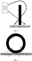
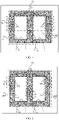
- FIG. 1 and FIG. 2 show some prior-art solutions of current transformers for detecting a differential mode current.
- a current transformer includes only a magnetic core and a secondary-side winding. When the current transformer is connected to a circuit, a first cable through which a positive current passes is forward inserted, and a second cable through which a negative current passes is reversely inserted. In this solution, if the first cable and the second cable are wrongly inserted in directions, a differential mode current cannot be independently measured.
- a current transformer includes a magnetic ring, a first primary-side winding, a second primary-side winding, and a secondary-side winding.
- the first primary-side winding, the second primary-side winding, and the secondary-side winding are all wound around the magnetic ring.
- Lead-out pins of the first primary-side winding are crossed, and lead-out pins of the second primary-side winding are not crossed.
- the lead-out pins of the first primary-side winding need to be crossed, the first primary-side winding needs to be bent, and this is difficult in processing.
- a first primary-side winding and a second primary-side winding respectively pass through two different closed magnetic circuits of a magnetic core without bending the primary-side winding, and such a structure is simple.
- a current transformer When a current transformer is connected to a circuit, only one lead-out pin of a first primary-side winding and one lead-out pin of a second primary-side winding need to be connected to the circuit, so that a differential mode current can be independently measured without threading.
- the solution in this application may be applied to a circuit in which a differential mode current and/or a common mode current need/needs to be independently detected.
- the solution may be applied to an arcing detection apparatus.
- a circuit formed by connecting two primary-side windings of the current transformer in this application to a circuit may be shown in FIG. 3.
- FIG. 3 is a schematic diagram of the circuit formed by connecting the two primary-side windings of the current transformer to the circuit according to an embodiment of this application. As shown in the diagram, the two primary-side windings of the current transformer are respectively connected to two parallel power lines (L1 and L2). I1 and I2 have a same value but have opposite directions, and I1 and I2 are differential mode currents in the two power lines.
- I3 and I4 have a same direction, and I3 and I4 are common mode currents in the two power lines.
- a secondary-side winding of the current transformer in this application is connected to a current detection circuit. One end of the secondary-side winding of the current transformer is grounded, and the other end of the current transformer is connected to a detection apparatus. For example, the other end of the current transformer is connected to a galvanometer, or the secondary-side winding of the current transformer is connected to a pin of a processor, or the like.
- FIG. 4 is a schematic structural diagram of a current transformer according to an embodiment of this application.
- a current transformer 10 includes a magnetic core 11, a first primary-side winding 12, a second primary-side winding 13, and a first secondary-side winding 14.
- the magnetic core 11 includes a first closed magnetic circuit 201 and a second closed magnetic circuit 202.
- the first closed magnetic circuit 201 is formed by connecting a first magnetic core structure 111 and a second magnetic core structure 112
- the second closed magnetic circuit 202 is formed by connecting the first magnetic core structure 111 and a third magnetic core structure 113
- the first magnetic core structure 111 is a magnetic core structure common to the first closed magnetic circuit 201 and the second closed magnetic circuit 202.
- the first primary-side winding 12 passes through the first closed magnetic circuit 201.
- the second primary-side winding 13 passes through the second closed magnetic circuit 202.
- the first secondary-side winding is wound around the first magnetic core structure 111.
- the magnetic flux is a scalar.
- the positive direction and the negative direction of the magnetic flux are related to a magnetic field direction of a magnetic field that passes through a cross section of the magnetic core.
- the direction of the magnetic field is the positive direction of the magnetic flux.
- FIG. 5 is a schematic diagram of a direction of a magnetic flux generated in a magnetic core when an electrified current that flows through a first primary-side winding and an electrified current that flows through a second primary-side winding have a same direction.
- a direction of the electrified current i1 that flows through the first primary-side winding and a direction of the electrified current i2 that flows through the second primary-side winding are both perpendicular to paper outward.
- the i1 generates a first magnetic field
- the i2 generates a second magnetic field
- both the first magnetic field and the second magnetic field have a counter-clockwise direction.
- a magnetic field direction of the first magnetic field is upward, and a positive direction of a first magnetic flux ⁇ 1 generated by the i1 in the first magnetic core structure is upward; and a magnetic field direction of the second magnetic field is downward, and a positive direction of a second magnetic flux ⁇ 2 generated by the i2 in the first magnetic core structure is downward.
- FIG. 6 is a schematic diagram of a direction of a magnetic flux generated in a magnetic core when an electrified current that flows through a first primary-side winding and an electrified current that flows through a second primary-side winding have opposite directions.
- a direction of an electrified current i1 that flows through the first primary-side winding is perpendicular to paper inward
- a direction of an electrified current i2 that flows through the second primary-side winding is perpendicular to paper outward.
- the i1 generates a first magnetic field, and the first magnetic field has a clockwise direction.
- the i2 generates a second magnetic field, and the second magnetic field has a counter-clockwise direction.
- a magnetic field direction of the first magnetic field is downward, that is, a positive direction of a first magnetic flux ⁇ 1 generated by the i1 in the first magnetic core structure is downward; and a magnetic field direction of the second magnetic field is downward, that is, a positive direction of a second magnetic flux ⁇ 2 generated by the i2 in the magnetic core is downward.
- the following uses an example to describe a case in which the magnetic fluxes generated by the electrified currents in the magnetic core are in the first magnetic core structure. It is assumed that the first primary-side winding and the second primary-side winding of the current transformer shown in FIG. 4 are connected to the circuit in FIG. 3 . There are the following several cases for a first current I5 that flows through the power line L1 and a second current I5 that flows through the power line L2. In a first case, the I5 and the I6 are currents with a same value but in opposite directions. In a second case, the I5 and the I6 are currents with a same value and in a same direction. In a third case, the I5 and the I6 are currents with different values and in a same direction.
- both the I5 and the I6 are 2 A, a current direction of the I5 is perpendicular to paper inward, and a current direction of the I6 is perpendicular to paper outward.
- a first magnetic flux ⁇ 1 generated by the I5 in the first magnetic core structure is equal to a second magnetic flux ⁇ 2 generated by the I6 in the first magnetic core structure.
- both the I5 and the I6 are 2 A, and the current direction of the I5 and the current direction of the I6 are perpendicular to paper outward.
- the I5 is 3 A
- the I6 is 1 A
- the current direction of the I5 and the current direction of the I6 are perpendicular to paper outward.
- the current I5 may be decomposed into a 2A-current i51 with a current direction perpendicular to paper outward and a 2A-current i52 with a current direction perpendicular to paper outward.
- the current I6 is decomposed into a 2A-current i61 with a current direction perpendicular to paper outward and a 1A-current i62 with a current direction perpendicular to paper inward.
- a magnetic flux ⁇ 51 generated by the current i51 in the first magnetic core is equal to a magnetic flux ⁇ 61 generated by the current i61 in the first magnetic core.
- a magnetic flux ⁇ 52 generated by the current i52 in the first magnetic core is equal to a magnetic flux ⁇ 62 generated by the current i62 in the first magnetic core.
- the two currents are equal to a group of currents with a same value and in a same direction and a group of currents with different values and in a same direction.
- Magnetic fluxes generated by the currents with the same value and in the same direction in the first magnetic core structure are superimposed, and magnetic fluxes generated by currents in the first magnetic core structure with different values and in the same direction cancel each other out.
- the currents with the same value and in the same direction are the differential mode currents.
- magnetic fluxes in the first magnetic core structure are mainly magnetic fluxes generated by the differential mode currents that pass through the first primary-side winding and the second primary-side winding.
- An induced current generated by the first secondary-side winding wound around the first magnetic core structure is an induced current corresponding to the differential mode current. That is, a current detected by the first secondary-side winding is a differential mode current, so that the differential mode current is independently measured.
- FIG. 7 is a schematic structural diagram of another current transformer according to an embodiment of this application.
- a current transformer 30 includes a magnetic core 31, a first primary-side winding 32, a second primary-side winding 33, and a second secondary-side winding 34.
- the magnetic core 31 includes a first closed magnetic circuit 401 and a second closed magnetic circuit 402.
- a first magnetic core structure 311 and a second magnetic core structure 312 are connected to constitute the first closed magnetic circuit 401, and the first magnetic core structure 311 and a third magnetic core structure 313 are connected to constitute the second closed magnetic circuit 402.
- the first magnetic core structure 311 is a magnetic core structure common to the first closed magnetic circuit 401 and the second closed magnetic circuit 402.
- the first primary-side winding 32 passes through the first closed magnetic circuit 401, and the second primary-side winding 33 passes through the second closed magnetic circuit 402.
- a first winding 341 of the second secondary-side winding 34 is wound around the second magnetic core structure 312, a second winding 342 of the second secondary-side winding 34 is wound around the third magnetic core structure 313, and the first winding 341 and the second winding 342 are serially connected.
- the direction of the electrified current i1 that flows through the first primary-side winding and the direction of the electrified current i2 that flows through the second primary-side winding are both perpendicular to paper outward.
- the i1 generates the first magnetic field
- the i2 generates the second magnetic field.
- the magnetic field direction of the first magnetic field is downward, and a positive direction of a third magnetic flux ⁇ 31 generated by the i1 in the second magnetic core structure is downward; and a magnetic field direction of the second magnetic field is downward, and a fourth magnetic flux ⁇ 41 generated by the i2 in the second magnetic core structure is downward.
- the magnetic field direction of the first magnetic field is upward, and a positive direction of a third magnetic flux ⁇ 32 generated by the i1 in the third magnetic core structure is upward; and the magnetic field direction of the second magnetic field is upward, and a positive direction of a fourth magnetic flux ⁇ 42 generated by the i2 in the second magnetic core structure is upward.
- the direction of the electrified current i1 that flows through the first primary-side winding is perpendicular to paper inward
- the direction of the electrified current i2 that flows through the second primary-side winding is perpendicular to paper outward.
- the i1 generates the first magnetic field
- the i2 generates the second magnetic field.
- the magnetic field direction of the first magnetic field is upward
- a positive direction of a fourth magnetic flux ⁇ 41 generated by the i2 in the second magnetic core structure is downward.
- the magnetic field direction of the first magnetic field is downward, and a positive direction of a third magnetic flux ⁇ 32 generated by the i1 in the third magnetic core structure is downward; and the magnetic field direction of the second magnetic field is upward, and a positive direction of a fourth magnetic flux ⁇ 42 generated by the i2 in the second magnetic core structure is upward.
- magnetic fluxes generated by the two electrified currents in the second magnetic core structure have different directions: a positive direction and a negative direction; magnetic fluxes generated in the third magnetic core structure have different directions: a positive direction and a negative direction; and the magnetic fluxes cancel each other out in the second magnetic core structure and the magnetic fluxes cancel each other out in the third magnetic core structure.
- the differential mode currents have opposite directions and a same value, and the common mode currents have a same direction.
- Magnetic fluxes generated by the differential mode currents in the second magnetic core structure cancel each other out, and magnetic fluxes generated by the common mode currents in the second magnetic core structure are superimposed.
- the magnetic fluxes in the second magnetic core structure are magnetic fluxes generated by the common mode currents passing through the first primary-side winding and the second primary-side winding.
- An induced current generated by the first winding of the second secondary-side winding wound around the second magnetic core structure is an induced current corresponding to the common mode currents.
- Magnetic fluxes generated by the differential mode currents in the third magnetic core structure cancel each other out, and magnetic fluxes generated by the common mode currents in the third magnetic core structure are superimposed.
- the magnetic fluxes in the third magnetic core structure are mainly magnetic fluxes generated by the common mode currents passing through the first primary-side winding and the second primary-side winding.
- An induced current generated by the second winding of the second secondary-side winding in the third magnetic core structure is an induced current corresponding to the common mode currents.
- the first winding and the second winding are serially connected, and a current detected by the second secondary-side winding is a common mode current, so that the common mode current can be independently measured.
- one current transformer may be configured to detect both the differential mode current and the common mode current.
- FIG. 8 is a schematic structural diagram of still another current transformer according to an embodiment of this application.
- a current transformer 50 includes a magnetic core 51, a first primary-side winding 52, a second primary-side winding 53, a first secondary-side winding 54, and a second secondary-side winding 55.
- the magnetic core 51 includes a first closed magnetic circuit 601 and a second closed magnetic circuit 602.
- the first closed magnetic circuit 601 is formed by connecting a first magnetic core structure 511 and a second magnetic core structure 512
- the second closed magnetic circuit 602 is formed by connecting the first magnetic core structure 511 and a third magnetic core structure 513
- the first magnetic core structure 511 is a magnetic core structure common to the first closed magnetic circuit 601 and the second closed magnetic circuit 602.
- the first primary-side winding 52 passes through the first closed magnetic circuit 601
- the second primary-side winding 53 passes through the second closed magnetic circuit 602.
- the first secondary-side winding is wound around the first magnetic core structure 511.
- a first winding 551 of the second secondary-side winding 55 is wound around the second magnetic core structure 512
- a second winding 552 of the second secondary-side winding 55 is wound around the third magnetic core structure 513
- the first winding 551 and the second winding 552 are serially connected.
- the foregoing describes the positive direction and the negative direction of the magnetic fluxes generated by the electrified currents that flow through the first primary-side winding and the second primary-side winding in the first magnetic core structure, the second magnetic core structure, and the third magnetic core structure. Details are not described herein again. It can be learned from the foregoing content that the current detected by the first secondary-side winding is the differential mode current, so that the differential mode current can be independently measured; and the current detected by the second secondary-side winding is the common mode current, so that the common mode current can be independently measured. That is, the current transformer in this embodiment of this application can independently measure both the common mode current and the differential mode current.
- the first primary-side winding, the second primary-side winding, the first secondary-side winding, and/or the second secondary-side winding are/is insulated from each other.
- the first primary-side winding, the second primary-side winding, the first secondary-side winding, and/or the second secondary-side winding are/is constituted by a conductive coil and an insulation layer that is surrounded by the coil.
- the first secondary-side winding and/or the second secondary-side winding respectively have more coil turns than the first primary-side winding and the second primary-side winding.
- the first primary-side winding and the second primary-side winding each have one turn, and the first secondary-side winding and/or the second secondary-side winding each have five turns.
- a quantity of turns and a turn ratio of the first primary-side winding, the second primary-side winding, the first secondary-side winding, and/or the second secondary-side winding may be designed depending on a specific requirement. This is not limited in this application.
- the first magnetic core structure, the second magnetic core structure, and the third magnetic core structure are made of a soft magnetic material for magnetic line transmission in a magnetic circuit.
- the soft magnetic material includes but is not limited to a soft iron, a soft magnetic alloy, a ferrite material, and a silicon steel sheet.
- the first magnetic core structure, the second magnetic core structure, and the third magnetic core structure may have a same soft magnetic material.
- the second magnetic core structure and the third magnetic core structure may be magnetic core structures that have some same features.
- the second magnetic core structure and the third magnetic core structure have a same size and a same shape, or the second magnetic core structure and the third magnetic core structure have a same magnetic resistance, or a magnetic permeability of the second magnetic core structure is the same as a third magnetic permeability.
- the second magnetic core structure and the third magnetic core structure may be two completely same magnetic core structures.
- that the second magnetic core structure is completely the same as the third magnetic core structure means that the size, the shape, the magnetic resistance, the magnetic permeability, and the like of the second magnetic core structure are the same as those of the third magnetic core structure.
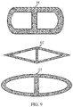
- the second magnetic core structure may be a "U"-shaped magnetic core structure, an arc-shaped magnetic core structure, an angle-shaped magnetic core structure, or the like.
- the third magnetic core structure may be a "U"-shaped magnetic core structure, an arc-shaped magnetic core structure, an angle-shaped magnetic core structure, or the like.
- a shape and a size of the second magnetic core structure and a shape and a size of the third magnetic core structure are not limited in this application.
- both a second magnetic core structure and a third magnetic core structure of a magnetic core 01 are "U"-shaped magnetic core structures.
- a second magnetic core structure and a third magnetic core structure of a magnetic core 02 are angle-shaped magnetic core structures, and both a second magnetic core structure and a third magnetic core structure of a magnetic core 03 are arc-shaped magnetic core structures.
- Embodiment 1 A current transformer, comprising a magnetic core, a first primary-side winding, a second primary-side winding, and a first secondary-side winding, wherein
- Embodiment 2 The current transformer according to embodiment 1, wherein a current that is to be detected by the current transformer separately flows through the first primary-side winding and the second primary-side winding, and the first secondary-side winding outputs a detection signal of the current transformer.
- Embodiment 3 The current transformer according to embodiment 1, wherein the second magnetic core structure is a "U"-shaped magnetic core structure;
- Embodiment 4 The current transformer according to embodiments 1 to 3, wherein the second magnetic core structure and the third magnetic core structure have a same size and a same shape.
- Embodiment 5 The current transformer according to any one of embodiments 1 to 4, wherein the second magnetic core structure and the third magnetic core structure have a same magnetic resistance.
- Embodiment 6 The current transformer according to any one of embodiments 1 to 5, wherein the first primary-side winding is wound around a joint between the first magnetic core structure and the second magnetic core structure, and the second primary-side winding is wound around a joint between the first magnetic core structure and the third magnetic core structure.
- Embodiment 7 A current transformer, comprising a magnetic core, a first primary-side winding, a second primary-side winding, and a second secondary-side winding, wherein
- Embodiment 8 The current transformer according to embodiment 7, wherein a current that is to be detected by the current transformer separately flows through the first primary-side winding and the second primary-side winding, and the second secondary-side winding outputs a detection signal of the current transformer.
- Embodiment 9 The current transformer according to embodiment 7, wherein the second magnetic core structure is a "U"-shaped magnetic core structure;
- Embodiment 10 The current transformer according to embodiments 7 to 9, wherein the second magnetic core structure and the third magnetic core structure have a same size and a same shape.
- Embodiment 11 The current transformer according to any one of embodiments 7 to 10, wherein the second magnetic core structure and the third magnetic core structure have a same magnetic resistance.
- Embodiment 12 The current transformer according to any one of embodiments 7 to 11, wherein the first primary-side winding is wound around a joint between the first magnetic core structure and the second magnetic core structure, and the second primary-side winding is wound around a joint between the first magnetic core structure and the third magnetic core structure.
- a magnetic resistance of a first closed magnetic circuit and a magnetic resistance of a second closed magnetic circuit are reduced as much as possible, to increase a common-mode/differential-mode suppression capability of a current transformer.
- a magnetic resistance of the first magnetic core structure may be reduced, so as to reduce the magnetic resistance of the first closed magnetic circuit and the magnetic resistance of the second closed magnetic circuit; or a magnetic resistance of the second magnetic core structure and a magnetic resistance of the third magnetic core structure may be reduced, so as to reduce the magnetic resistance of the first closed magnetic circuit and the magnetic resistance of the second closed magnetic circuit.
- the current transformer when the current transformer is configured to detect the differential mode current, the current transformer may cancel the magnetic flux generated by the common mode current out, eliminate interference of the common mode current, and accurately collect a differential-mode-current signal.
- the current transformer when the current transformer is configured to detect the common mode current, the current transformer may cancel the magnetic flux generated by the differential mode current out, eliminate interference of the differential mode current, and accurately collect a differential-mode-current signal.
- the current transformer in this application may independently measure the differential mode current and the common mode current.
Landscapes
- Engineering & Computer Science (AREA)
- Power Engineering (AREA)
- Physics & Mathematics (AREA)
- General Physics & Mathematics (AREA)
- Transformers For Measuring Instruments (AREA)
- Measuring Instrument Details And Bridges, And Automatic Balancing Devices (AREA)
Applications Claiming Priority (3)
| Application Number | Priority Date | Filing Date | Title |
|---|---|---|---|
| CN201711196326.6A CN108039267B (zh) | 2017-11-25 | 2017-11-25 | 电流互感器 |
| PCT/CN2018/115588 WO2019100996A1 (fr) | 2017-11-25 | 2018-11-15 | Transformateur de courant |
| EP18880707.7A EP3709320B1 (fr) | 2017-11-25 | 2018-11-15 | Transformateur de courant |
Related Parent Applications (2)
| Application Number | Title | Priority Date | Filing Date |
|---|---|---|---|
| EP18880707.7A Division-Into EP3709320B1 (fr) | 2017-11-25 | 2018-11-15 | Transformateur de courant |
| EP18880707.7A Division EP3709320B1 (fr) | 2017-11-25 | 2018-11-15 | Transformateur de courant |
Publications (1)
| Publication Number | Publication Date |
|---|---|
| EP4016565A1 true EP4016565A1 (fr) | 2022-06-22 |
Family
ID=62093495
Family Applications (2)
| Application Number | Title | Priority Date | Filing Date |
|---|---|---|---|
| EP21204382.2A Pending EP4016565A1 (fr) | 2017-11-25 | 2018-11-15 | Transformateur de courant |
| EP18880707.7A Active EP3709320B1 (fr) | 2017-11-25 | 2018-11-15 | Transformateur de courant |
Family Applications After (1)
| Application Number | Title | Priority Date | Filing Date |
|---|---|---|---|
| EP18880707.7A Active EP3709320B1 (fr) | 2017-11-25 | 2018-11-15 | Transformateur de courant |
Country Status (4)
| Country | Link |
|---|---|
| US (1) | US11742139B2 (fr) |
| EP (2) | EP4016565A1 (fr) |
| CN (2) | CN108039267B (fr) |
| WO (1) | WO2019100996A1 (fr) |
Families Citing this family (6)
| Publication number | Priority date | Publication date | Assignee | Title |
|---|---|---|---|---|
| CN108039267B (zh) | 2017-11-25 | 2019-10-25 | 华为数字技术(苏州)有限公司 | 电流互感器 |
| CN111245209B (zh) * | 2020-01-19 | 2021-08-24 | 珠海格力电器股份有限公司 | 一种干扰信号抑制电路及电器设备 |
| EP4152350A4 (fr) * | 2020-06-10 | 2023-07-26 | Huawei Digital Power Technologies Co., Ltd. | Inducteur et appareil associé |
| CN114019218B (zh) * | 2021-11-04 | 2024-04-09 | 国网河北省电力有限公司电力科学研究院 | 一种双通道零磁通电流传感器 |
| CN115149900B (zh) * | 2022-06-27 | 2024-11-22 | 华为数字能源技术有限公司 | 光伏变换器以及光伏发电系统 |
| CN116936236B (zh) * | 2023-06-29 | 2024-05-31 | 上海正泰电源系统有限公司 | 一种改善直流电弧检测精度的检测互感器及方法 |
Citations (1)
| Publication number | Priority date | Publication date | Assignee | Title |
|---|---|---|---|---|
| US5793196A (en) * | 1996-07-03 | 1998-08-11 | Sundstrand Corporation | Current transformer for measuring differential-mode and common-mode current |
Family Cites Families (20)
| Publication number | Priority date | Publication date | Assignee | Title |
|---|---|---|---|---|
| US2802981A (en) * | 1953-12-23 | 1957-08-13 | Hobart Brothers Co | Transformer welder with electrically adjustable leakage reactance |
| DE19637733C1 (de) * | 1996-09-16 | 1998-01-22 | Vacuumschmelze Gmbh | Stromkompensierte Funkentstördrossel mit erhöhter Streuinduktivität |
| US6683766B1 (en) | 2002-02-11 | 2004-01-27 | Yazaki North-America, Inc. | DC arc detection and prevention circuit and method |
| US20080074227A1 (en) * | 2006-09-21 | 2008-03-27 | Ford Global Technologies, Llc | Inductor topologies with substantial common-mode and differential-mode inductance |
| JP2009295839A (ja) * | 2008-06-06 | 2009-12-17 | Chugoku Electric Power Co Inc:The | クロス貫通変流器、端子台および保護継電装置 |
| CN101552116B (zh) * | 2008-12-26 | 2011-06-08 | 魏明 | 分磁路变压器 |
| CN201444443U (zh) * | 2009-01-16 | 2010-04-28 | 魏明 | 部分控制变压器 |
| CN102074330A (zh) * | 2010-11-30 | 2011-05-25 | 薛韬 | 多相差模和共模共体电抗器 |
| CN102394168B (zh) * | 2011-03-09 | 2014-04-30 | 北京四方继保自动化股份有限公司 | 末屏差分数字输出互感器 |
| LT6025B (lt) * | 2012-06-14 | 2014-05-26 | Sigitas ŽVIRBLIS | Apsaugos nuo neapskaitytos elektros energijos vartojimo modulis |
| CN102709042B (zh) * | 2012-06-21 | 2015-06-10 | 陈德才 | 一种电流互感器 |
| CN103595367B (zh) * | 2013-11-07 | 2017-03-08 | 华为技术有限公司 | 一种磁集成器件及一种功率转换电路 |
| CN103700473B (zh) * | 2013-12-12 | 2017-11-28 | 华为技术有限公司 | 耦合电感和功率变换器 |
| CN103871716A (zh) * | 2014-02-18 | 2014-06-18 | 同济大学 | 一种磁集成结构 |
| CN204464038U (zh) * | 2015-03-16 | 2015-07-08 | 中国计量学院 | 基于正交坐标系变换输出的三相组合式互感器 |
| US10378242B2 (en) * | 2015-04-14 | 2019-08-13 | Hanchett Entry Systems, Inc. | Constant-current controller for an inductive load |
| CN205303103U (zh) * | 2016-01-15 | 2016-06-08 | 德特蒙有限公司 | 具有共模差模电感功能的电感装置 |
| CN107370123B (zh) | 2016-05-13 | 2019-02-26 | 上海电科电器科技有限公司 | 电弧故障检测装置 |
| CN108039267B (zh) * | 2017-11-25 | 2019-10-25 | 华为数字技术(苏州)有限公司 | 电流互感器 |
| CN109802441B (zh) | 2019-03-18 | 2021-06-11 | 阳光电源股份有限公司 | 光伏逆变系统的直流电弧故障检测方法、装置及系统 |
-
2017
- 2017-11-25 CN CN201711196326.6A patent/CN108039267B/zh active Active
-
2018
- 2018-11-15 EP EP21204382.2A patent/EP4016565A1/fr active Pending
- 2018-11-15 WO PCT/CN2018/115588 patent/WO2019100996A1/fr not_active Ceased
- 2018-11-15 CN CN201880076113.6A patent/CN111771250B/zh active Active
- 2018-11-15 EP EP18880707.7A patent/EP3709320B1/fr active Active
-
2020
- 2020-05-22 US US16/881,366 patent/US11742139B2/en active Active
Patent Citations (1)
| Publication number | Priority date | Publication date | Assignee | Title |
|---|---|---|---|---|
| US5793196A (en) * | 1996-07-03 | 1998-08-11 | Sundstrand Corporation | Current transformer for measuring differential-mode and common-mode current |
Also Published As
| Publication number | Publication date |
|---|---|
| CN108039267A (zh) | 2018-05-15 |
| EP3709320B1 (fr) | 2022-01-05 |
| WO2019100996A1 (fr) | 2019-05-31 |
| EP3709320A4 (fr) | 2020-09-16 |
| CN111771250B (zh) | 2022-08-26 |
| US20200286681A1 (en) | 2020-09-10 |
| EP3709320A1 (fr) | 2020-09-16 |
| US11742139B2 (en) | 2023-08-29 |
| CN108039267B (zh) | 2019-10-25 |
| CN111771250A (zh) | 2020-10-13 |
Similar Documents
| Publication | Publication Date | Title |
|---|---|---|
| EP3709320B1 (fr) | Transformateur de courant | |
| CN103384446B (zh) | 用于电弧故障检测的装置和方法 | |
| US10365305B2 (en) | Rogowski coil type sensor for measuring current, measuring device and electrical circuit breaker including such a sensor, and method for winding such a sensor | |
| CN105308840B (zh) | 用于辨别电弧的方法与设备 | |
| CN105264389B (zh) | 电流测量装置以及电流计算方法 | |
| CN103308743A (zh) | 直流电流计量装置 | |
| CN201622921U (zh) | 一种降低反激式变换器共模干扰的变压器及反激式变换器 | |
| JP6298581B2 (ja) | 電流検出装置及びこれを備えた変電設備 | |
| JP2018072228A (ja) | 電流検出装置 | |
| US11313917B2 (en) | Electric current sensor for detecting leakage current | |
| CN107424815B (zh) | 一种采用减匝补偿的双级电流互感器 | |
| CN108519508A (zh) | 一种测量交流与直流电流的比较仪 | |
| CN102881438A (zh) | 低压断路器配套用电子式电流互感器 | |
| CN105830182B (zh) | 用于减小在三相变压器的铁心中的单向磁通量分量的设备和方法 | |
| CN117995538A (zh) | 一种光伏系统的磁集成装置、光伏系统 | |
| CN215680366U (zh) | 一种反激式变压器及其测试结构 | |
| JP7208830B2 (ja) | 電流センサ素子 | |
| CN110310808A (zh) | 一种电流互感器及断路器 | |
| CN201918253U (zh) | 一种电流互感器 | |
| CN207557333U (zh) | 一种直流电流比较测量装置 | |
| CN113049867B (zh) | 用于测量电流的dc分量的测量设备及关联测量方法 | |
| CN111157775A (zh) | 一种双线圈电流传感器 | |
| Givi et al. | Three dimensional finite element modeling of a current transformer and analyzing its operation under normal condition | |
| RU2551632C2 (ru) | Измерительное устройство дифференциальной токовой защиты шин | |
| JPH01141364A (ja) | 交流電流計測装置 |
Legal Events
| Date | Code | Title | Description |
|---|---|---|---|
| PUAI | Public reference made under article 153(3) epc to a published international application that has entered the european phase |
Free format text: ORIGINAL CODE: 0009012 |
|
| STAA | Information on the status of an ep patent application or granted ep patent |
Free format text: STATUS: THE APPLICATION HAS BEEN PUBLISHED |
|
| AC | Divisional application: reference to earlier application |
Ref document number: 3709320 Country of ref document: EP Kind code of ref document: P |
|
| AK | Designated contracting states |
Kind code of ref document: A1 Designated state(s): AL AT BE BG CH CY CZ DE DK EE ES FI FR GB GR HR HU IE IS IT LI LT LU LV MC MK MT NL NO PL PT RO RS SE SI SK SM TR |
|
| STAA | Information on the status of an ep patent application or granted ep patent |
Free format text: STATUS: REQUEST FOR EXAMINATION WAS MADE |
|
| 17P | Request for examination filed |
Effective date: 20221222 |
|
| RBV | Designated contracting states (corrected) |
Designated state(s): AL AT BE BG CH CY CZ DE DK EE ES FI FR GB GR HR HU IE IS IT LI LT LU LV MC MK MT NL NO PL PT RO RS SE SI SK SM TR |
|
| STAA | Information on the status of an ep patent application or granted ep patent |
Free format text: STATUS: EXAMINATION IS IN PROGRESS |
|
| 17Q | First examination report despatched |
Effective date: 20240924 |