EP4016665A1 - Procédé et appareil de fabrication d'électrode pour batterie auxiliaire utilisant un laser et électrode pour batterie auxiliaire fabriquée par ceux-ci - Google Patents
Procédé et appareil de fabrication d'électrode pour batterie auxiliaire utilisant un laser et électrode pour batterie auxiliaire fabriquée par ceux-ci Download PDFInfo
- Publication number
- EP4016665A1 EP4016665A1 EP20907522.5A EP20907522A EP4016665A1 EP 4016665 A1 EP4016665 A1 EP 4016665A1 EP 20907522 A EP20907522 A EP 20907522A EP 4016665 A1 EP4016665 A1 EP 4016665A1
- Authority
- EP
- European Patent Office
- Prior art keywords
- electrode
- holes
- manufacturing
- current collector
- electrode mixture
- Prior art date
- Legal status (The legal status is an assumption and is not a legal conclusion. Google has not performed a legal analysis and makes no representation as to the accuracy of the status listed.)
- Granted
Links
Images


Classifications
-
- B—PERFORMING OPERATIONS; TRANSPORTING
- B23—MACHINE TOOLS; METAL-WORKING NOT OTHERWISE PROVIDED FOR
- B23K—SOLDERING OR UNSOLDERING; WELDING; CLADDING OR PLATING BY SOLDERING OR WELDING; CUTTING BY APPLYING HEAT LOCALLY, e.g. FLAME CUTTING; WORKING BY LASER BEAM
- B23K26/00—Working by laser beam, e.g. welding, cutting or boring
- B23K26/02—Positioning or observing the workpiece, e.g. with respect to the point of impact; Aligning, aiming or focusing the laser beam
- B23K26/06—Shaping the laser beam, e.g. by masks or multi-focusing
- B23K26/062—Shaping the laser beam, e.g. by masks or multi-focusing by direct control of the laser beam
- B23K26/0622—Shaping the laser beam, e.g. by masks or multi-focusing by direct control of the laser beam by shaping pulses
-
- H—ELECTRICITY
- H01—ELECTRIC ELEMENTS
- H01M—PROCESSES OR MEANS, e.g. BATTERIES, FOR THE DIRECT CONVERSION OF CHEMICAL ENERGY INTO ELECTRICAL ENERGY
- H01M4/00—Electrodes
- H01M4/02—Electrodes composed of, or comprising, active material
- H01M4/04—Processes of manufacture in general
-
- B—PERFORMING OPERATIONS; TRANSPORTING
- B23—MACHINE TOOLS; METAL-WORKING NOT OTHERWISE PROVIDED FOR
- B23K—SOLDERING OR UNSOLDERING; WELDING; CLADDING OR PLATING BY SOLDERING OR WELDING; CUTTING BY APPLYING HEAT LOCALLY, e.g. FLAME CUTTING; WORKING BY LASER BEAM
- B23K26/00—Working by laser beam, e.g. welding, cutting or boring
- B23K26/08—Devices involving relative movement between laser beam and workpiece
- B23K26/082—Scanning systems, i.e. devices involving movement of the laser beam relative to the laser head
- B23K26/0821—Scanning systems, i.e. devices involving movement of the laser beam relative to the laser head using multifaceted mirrors, e.g. polygonal mirror
-
- B—PERFORMING OPERATIONS; TRANSPORTING
- B23—MACHINE TOOLS; METAL-WORKING NOT OTHERWISE PROVIDED FOR
- B23K—SOLDERING OR UNSOLDERING; WELDING; CLADDING OR PLATING BY SOLDERING OR WELDING; CUTTING BY APPLYING HEAT LOCALLY, e.g. FLAME CUTTING; WORKING BY LASER BEAM
- B23K26/00—Working by laser beam, e.g. welding, cutting or boring
- B23K26/08—Devices involving relative movement between laser beam and workpiece
- B23K26/083—Devices involving movement of the workpiece in at least one axial direction
- B23K26/0838—Devices involving movement of the workpiece in at least one axial direction by using an endless conveyor belt
- B23K26/0846—Devices involving movement of the workpiece in at least one axial direction by using an endless conveyor belt for moving elongated workpieces longitudinally, e.g. wire or strip material
-
- B—PERFORMING OPERATIONS; TRANSPORTING
- B23—MACHINE TOOLS; METAL-WORKING NOT OTHERWISE PROVIDED FOR
- B23K—SOLDERING OR UNSOLDERING; WELDING; CLADDING OR PLATING BY SOLDERING OR WELDING; CUTTING BY APPLYING HEAT LOCALLY, e.g. FLAME CUTTING; WORKING BY LASER BEAM
- B23K26/00—Working by laser beam, e.g. welding, cutting or boring
- B23K26/36—Removing material
- B23K26/362—Laser etching
-
- B—PERFORMING OPERATIONS; TRANSPORTING
- B23—MACHINE TOOLS; METAL-WORKING NOT OTHERWISE PROVIDED FOR
- B23K—SOLDERING OR UNSOLDERING; WELDING; CLADDING OR PLATING BY SOLDERING OR WELDING; CUTTING BY APPLYING HEAT LOCALLY, e.g. FLAME CUTTING; WORKING BY LASER BEAM
- B23K26/00—Working by laser beam, e.g. welding, cutting or boring
- B23K26/36—Removing material
- B23K26/38—Removing material by boring or cutting
- B23K26/382—Removing material by boring or cutting by boring
- B23K26/386—Removing material by boring or cutting by boring of blind holes
-
- B—PERFORMING OPERATIONS; TRANSPORTING
- B23—MACHINE TOOLS; METAL-WORKING NOT OTHERWISE PROVIDED FOR
- B23K—SOLDERING OR UNSOLDERING; WELDING; CLADDING OR PLATING BY SOLDERING OR WELDING; CUTTING BY APPLYING HEAT LOCALLY, e.g. FLAME CUTTING; WORKING BY LASER BEAM
- B23K26/00—Working by laser beam, e.g. welding, cutting or boring
- B23K26/36—Removing material
- B23K26/40—Removing material taking account of the properties of the material involved
- B23K26/402—Removing material taking account of the properties of the material involved involving non-metallic material, e.g. isolators
-
- H—ELECTRICITY
- H01—ELECTRIC ELEMENTS
- H01M—PROCESSES OR MEANS, e.g. BATTERIES, FOR THE DIRECT CONVERSION OF CHEMICAL ENERGY INTO ELECTRICAL ENERGY
- H01M4/00—Electrodes
- H01M4/02—Electrodes composed of, or comprising, active material
- H01M4/04—Processes of manufacture in general
- H01M4/0402—Methods of deposition of the material
- H01M4/0404—Methods of deposition of the material by coating on electrode collectors
-
- H—ELECTRICITY
- H01—ELECTRIC ELEMENTS
- H01M—PROCESSES OR MEANS, e.g. BATTERIES, FOR THE DIRECT CONVERSION OF CHEMICAL ENERGY INTO ELECTRICAL ENERGY
- H01M4/00—Electrodes
- H01M4/02—Electrodes composed of, or comprising, active material
- H01M4/04—Processes of manufacture in general
- H01M4/043—Processes of manufacture in general involving compressing or compaction
- H01M4/0435—Rolling or calendering
-
- H—ELECTRICITY
- H01—ELECTRIC ELEMENTS
- H01M—PROCESSES OR MEANS, e.g. BATTERIES, FOR THE DIRECT CONVERSION OF CHEMICAL ENERGY INTO ELECTRICAL ENERGY
- H01M4/00—Electrodes
- H01M4/02—Electrodes composed of, or comprising, active material
- H01M4/04—Processes of manufacture in general
- H01M4/0471—Processes of manufacture in general involving thermal treatment, e.g. firing, sintering, backing particulate active material, thermal decomposition, pyrolysis
-
- H—ELECTRICITY
- H01—ELECTRIC ELEMENTS
- H01M—PROCESSES OR MEANS, e.g. BATTERIES, FOR THE DIRECT CONVERSION OF CHEMICAL ENERGY INTO ELECTRICAL ENERGY
- H01M4/00—Electrodes
- H01M4/02—Electrodes composed of, or comprising, active material
- H01M4/13—Electrodes for accumulators with non-aqueous electrolyte, e.g. for lithium-accumulators; Processes of manufacture thereof
- H01M4/139—Processes of manufacture
-
- B—PERFORMING OPERATIONS; TRANSPORTING
- B23—MACHINE TOOLS; METAL-WORKING NOT OTHERWISE PROVIDED FOR
- B23K—SOLDERING OR UNSOLDERING; WELDING; CLADDING OR PLATING BY SOLDERING OR WELDING; CUTTING BY APPLYING HEAT LOCALLY, e.g. FLAME CUTTING; WORKING BY LASER BEAM
- B23K2101/00—Articles made by soldering, welding or cutting
- B23K2101/36—Electric or electronic devices
-
- B—PERFORMING OPERATIONS; TRANSPORTING
- B23—MACHINE TOOLS; METAL-WORKING NOT OTHERWISE PROVIDED FOR
- B23K—SOLDERING OR UNSOLDERING; WELDING; CLADDING OR PLATING BY SOLDERING OR WELDING; CUTTING BY APPLYING HEAT LOCALLY, e.g. FLAME CUTTING; WORKING BY LASER BEAM
- B23K2103/00—Materials to be soldered, welded or cut
- B23K2103/16—Composite materials
-
- H—ELECTRICITY
- H01—ELECTRIC ELEMENTS
- H01M—PROCESSES OR MEANS, e.g. BATTERIES, FOR THE DIRECT CONVERSION OF CHEMICAL ENERGY INTO ELECTRICAL ENERGY
- H01M4/00—Electrodes
- H01M4/02—Electrodes composed of, or comprising, active material
- H01M2004/021—Physical characteristics, e.g. porosity, surface area
-
- Y—GENERAL TAGGING OF NEW TECHNOLOGICAL DEVELOPMENTS; GENERAL TAGGING OF CROSS-SECTIONAL TECHNOLOGIES SPANNING OVER SEVERAL SECTIONS OF THE IPC; TECHNICAL SUBJECTS COVERED BY FORMER USPC CROSS-REFERENCE ART COLLECTIONS [XRACs] AND DIGESTS
- Y02—TECHNOLOGIES OR APPLICATIONS FOR MITIGATION OR ADAPTATION AGAINST CLIMATE CHANGE
- Y02E—REDUCTION OF GREENHOUSE GAS [GHG] EMISSIONS, RELATED TO ENERGY GENERATION, TRANSMISSION OR DISTRIBUTION
- Y02E60/00—Enabling technologies; Technologies with a potential or indirect contribution to GHG emissions mitigation
- Y02E60/10—Energy storage using batteries
Definitions
- the present disclosure relates to a manufacturing apparatus and a manufacturing method of an electrode for a secondary battery using a laser, and an electrode for a secondary battery manufactured by the same, and more particularly, to a manufacturing apparatus and a manufacturing method of an electrode for a secondary battery which forms a hole in the electrode mixture using a laser, and an electrode for a secondary battery manufactured by the same.
- a secondary battery is a representative example of an electrochemical device that utilizes such electrochemical energy, and the range of use thereof tends to be gradually expanding.
- the capacity of the secondary battery has increased and the electrode density has also increased.
- the porosity is reduced, the bending degree is increased, and the movement path of lithium ions is increased, which causes a problem that the ion conductivity is decreased, and the power characteristics are decreased accordingly. That is, as the electrode density of the secondary battery is enhanced and the capacity is increased, the power characteristic decreases.
- the present disclosure has been designed to solve the above-mentioned problems, and it is an object of the present disclosure to form a large number of holes in the electrode mixture by laser etching to reduce the bending degree, thereby improving power characteristics while minimizing capacity reduction of a secondary battery including the same.
- an apparatus for manufacturing an electrode for a secondary battery comprising:
- the transfer unit may transfer the sheet type current collector at a speed of 40 m/min to 80 m/min.
- the nanosecond laser may satisfy the following conditions 1 to 4.
- the plurality of holes formed by laser etching may be formed in a conical shape whose diameter decreases in the direction from the surface portion of the electrode mixture to the sheet type current collector.
- the holes may be formed such that a diameter at the surface portion of the electrode mixture and a depth in the direction from the surface portion of the electrode mixture to the sheet type current collector is in a ratio of 1:1 to 2:1.
- the diameter of the hole at the surface portion of the electrode mixture may be formed from 10 ⁇ m to 50 ⁇ m, and an interval between the respective holes may be formed from 100 ⁇ m to 500 ⁇ m, based on a conical interval between the respective holes located at a portion close to the current collector.
- the laser unit further includes a polygon mirror and thus, can etch through the polygon mirror at the time of laser etching.
- a method for manufacturing an electrode for a secondary battery comprising the steps of:
- the sheet type current collector can be transferred at a speed of 40 m/min to 80 m/min.
- the nanosecond laser can satisfy the following conditions 1 to 4.
- the large number of holes formed by laser etching may be formed in a conical shape whose diameter decreases in the direction from the surface portion of the electrode mixture to the sheet type current collector, and a diameter of the hole at the surface portion of the electrode mixture and a depth of hole in the direction from the surface portion of the electrode mixture to the sheet type current collector may be formed in a ratio of 1:1 to 2:1.
- the diameter of the holes at the surface portion of the electrode mixture may be specifically formed from 10 ⁇ m to 50 ⁇ m, and the interval between the respective holes may be formed from 100 ⁇ m to 500 ⁇ m, based a conical interval between the respective holes located in a portion close to the current collector.
- the laser unit further includes a polygon mirror and thus, can etch through the polygon mirror at the time of laser etching.
- an electrode for a secondary battery which is manufactured by the method of manufacturing an electrode, the electrode being characterize in that: an electrode mixture is formed on at least one surface of a current collector, and a large number of conical-shaped holes, in which a diameter at the surface portion of the electrode mixture and a depth in the direction from the surface portion of the electrode mixture to the sheet type current collector is in a ratio of 1:1 to 2:1, are formed in the electrode mixture so as to form a level difference in thickness.
- the diameter of the hole at the surface portion of the electrode mixture may be 10 ⁇ m to 50 ⁇ m and the interval between the respective holes may be 100 ⁇ m to 500 ⁇ m.
- a large number of holes having a level difference in thickness can be formed by using a laser in the electrode mixture to reduce the bending degree, thereby manufacturing an electrode with increased ionic conductivity, whereby the method provides the effects of improving the power characteristics and high rate characteristics of the secondary battery including the same.
- holes having a desired diameter and depth can be formed by performing irradiation twice or less, in consideration of the electrode process speed, thereby providing the effect of minimizing the loss of capacity.
- an apparatus for manufacturing an electrode for a secondary battery comprising:
- FIG. 1 schematically illustrates such an electrode manufacturing apparatus
- FIG. 2 schematically illustrates an electrode manufactured by such a manufacturing method.
- the electrode manufacturing apparatus includes:
- the unwinder 110 is composed of a structure in which the sheet type current collector 101 is wound on a roll.
- This unwinder 110 unwinds the sheet type current collector 101 and transfers the sheet-type current collector 101 by the transfer unit 120.
- the transfer unit 120 receives the sheet type current collector 101 unwound from the unwinder 110, and serves to transfer the sheet type current collector 101 to a rewinder 170 via a coating unit 130, a drying unit 140, a rolling unit 150, and a laser unit 160.
- the transfer unit 120 may be a roll.
- the sheet type current collector 101 may be transferred, for example, at a speed of 40 m/min to 80 m/min, and specifically, it can be transferred at a speed of 60m/min to 80m/min.
- the sheet type current collector 101 unwound from the unwinder 110 and transferred by the transfer unit 120 is transferred to the coating unit 130 by the transfer unit 120.
- the coating unit 130 coats the electrode active material slurry 102 onto the sheet type current collector 101.
- the coating unit is not limited as long as it is in a form capable of coating the electrode active material slurry, and it may be coated by a conventionally known coating device such as a coating die, a coating roll, or a slide-slot.
- FIG. 1 shows, as an example, a structure in which an electrode active material slurry is coated via a coating die.
- the coating unit 130 may be composed of a structure including: a coating die 131 provided with an outlet slot so that the electrode active material slurry 102 flows out to the outside toward the sheet type current collector 101, and a coater roll 132 which is arranged separately from the outlet slot of the coating die 131 at predetermined intervals, and transfers the sheet type current collector 101 by rotation so that the electrode active material slurry 102 can be coated onto the sheet type current collector 101 by the coating die 131.
- the sheet type current collector 101 coated with the electrode active material slurry 102 is transferred to the drying unit 140 by the transfer unit 120.
- the drying unit 140 is not limited as long as it is a device capable of forming the electrode mixture 103 by evaporating a solvent from the electrode active material slurry. It may have any conventionally known structure, and for example, the drying can be performed by a heating type and/or a hot air type.
- the electrode mixture 103 in a state where the solvent is evaporated is formed on the sheet type current collector 101, and the electrode mixture 103 is rolled through the rolling unit 150 so as to have an appropriate porosity and electrode density.
- the rolling unit 150 is in a form capable of rolling the electrode mixture, its device, structure, and the like are not limited, and for example, it may be in the form of rolling by adjusting the separation interval of the pair of rollers 151 and 152.
- the electrode mixture 103 on which the rolling has been completed is transferred to the laser unit 160 by the transfer unit 120, and the laser unit 160 forms a large number of holes 181 having a level difference T-t in thickness by etching the electrode mixture 103 using a laser.
- the laser unit 160 uses a nanosecond laser 161, and forms respective holes 181 by performing irradiation twice or less, and specifically, by performing irradiation once.
- the bending degree can be reduced while minimizing the reduction in capacity, which is preferable.
- the desired hole diameter and depth can be obtained only when the laser is irradiated several times on the electrode mixture. Performing irradiation twice or less allows the energy to spread widely, so that a spreading shaped hole are formed in which the depth of the hole is shallow and the diameter is wide.
- the loss of the electrode mixture becomes large, which leads to a reduction in the capacity of the secondary battery including the same, and thus is not preferable.
- the transfer speed of the transfer unit in the manufacturing process of the electrode according to the present disclosure is preferably 40 m/min to 80 m/min.
- the optimum hole shape must be obtained, and for this purpose, the nanosecond laser must be irradiated twice or less, specifically once, to form a level difference in thickness.
- the nanosecond laser can, specifically, satisfy the following conditions 1 to 4.
- the peak power becomes smaller and the hole is not properly formed.
- the pulse energy becomes too large, the peak power becomes too large, and the hole depth and diameter increases at the same time, so that the capacity loss becomes larger than the improvement of the power characteristics, which is thus not preferable.
- the holes 181 may be formed in a conical shape whose diameter decreases in the direction from the surface portion of the electrode mixture 103 to the sheet type current collector 101.
- the holes 181 may be formed such that the diameter (r) at the surface portion of the electrode mixture 103 and the depth (d) in the direction from the surface portion of the electrode mixture 103 to the sheet-shaped current collector 101 have the same size, or the diameter (r) may be greater than the depth (d).
- the diameter (r) and the depth (d) of the hole 181 may be formed in a ratio of 1:1 to 2:1, specifically, a ratio of 1:1 to 1.7:1, more specifically, a ratio of 1:1 to 1.5:1, most specifically, a ratio of 1:1 to 1.3:1.
- the diameter (r) at the surface portion of the electrode mixture of the hole 181 may be formed in a range of 10 ⁇ m to 50 ⁇ m, specifically, 20 ⁇ m to 45 ⁇ m, and more specifically 25 ⁇ m to 35 ⁇ m.
- the interval between the respective holes 181 may be formed in the range of 100 ⁇ m to 500 ⁇ m, specifically 200 ⁇ m to 400 ⁇ m, and more specifically 200 ⁇ m to 300 ⁇ m.
- the interval (w) between the holes 181 also affects the diameter (r) and depth (d) of the formed holes.
- the diameter (r) and the depth (d) of the holes is larger.
- the electrode binder is melted by a heat of the laser, so that the adhesion force between the electrode and the current collector, and the electrode adhesion force are lowered, so the possibility of separation of the electrode active material is high, and the current collector may be deformed by heat.
- the interval is larger than the above range, the effect of improving the power characteristics is slight.
- the laser unit 160 may further include a polygon mirror 162, and at the time of laser etching, it may be etched through the polygon mirror 162.
- the holes 181 can be formed at a higher speed even with a single laser source, which is more preferable when applied to a mass production process.
- the electrode sheet 180 which has been subjected to laser etching in the laser unit 160 to form a large number of holes 181, is wound by a roller-shaped rewinder 170.
- the rewinder 170 is composed of a structure in which the electrode sheet 180 is wound on a roll, similar to the unwinder 110.
- an electrode for a secondary battery comprising the steps of:
- the electrode active material slurry of step (a) contains the active material as described below.
- the type of the active material is determined depending on whether the electrode is a positive electrode or a negative electrode.
- the active material may include, for example, carbonaceous materials such as artificial graphite, natural graphite, graphitized carbon fibers and amorphous carbon; metallic compounds capable of alloying with lithium, such as Si, Al, Sn, Pb, Zn, Bi, In, Mg, Ga, Cd, Si alloy, Sn alloy or Al alloy; metal oxides capable of doping and undoping lithium, such as SiO x (0 ⁇ x ⁇ 2), SnO 2 , vanadium oxide and lithium vanadium oxide; or a composite including the above metallic compound and the carbonaceous material such as a Si-C composite or a Sn-C composite, or the like, and any one or a mixture of two or more of them may be used.
- carbonaceous materials such as artificial graphite, natural graphite, graphitized carbon fibers and amorphous carbon
- metallic compounds capable of alloying with lithium, such as Si, Al, Sn, Pb, Zn, Bi, In, Mg, Ga, Cd, Si alloy, Sn alloy or
- a metal lithium thin film may also be used as the negative electrode active material.
- both low crystalline carbon and high crystalline carbon may be used as the carbon material.
- Typical examples of the low crystalline carbon may be soft carbon and hard carbon.
- Typical examples of the high crystalline carbon may be amorphous, planar, flaky, spherical or fibrous natural or artificial graphite, Kish graphite, pyrolytic carbon, mesophase pitch based carbon fiber, meso-carbon microbeads, mesophase pitches, and high-temperature calcined carbon such as petroleum or coal tar pitch derived cokes.
- the electrode active material slurry may further include a conductive material and a binder, and optionally, may further include a filler.
- the conductive material is used to impart conductivity to the electrode, and the conductive material can be used without particular limitation as long as it has electronic conductivity without causing chemical changes in the battery to be configured.
- Specific examples thereof include carbon-based materials such as carbon black, acetylene black, ketjen black, channel black, furnace black, lamp black, thermal black and carbon fiber; graphite such as natural graphite and artificial graphite; metal powder or metal fibers such as copper, nickel, aluminum and silver; conductive whiskey such as zinc oxide and potassium titanate; conductive metal oxides such as titanium oxide; or a conductive polymer such as a polyphenylene derivative, and any one alone or a mixture of two or more of them may be used.
- the conductive material may be included in an amount of 0.5% to 10% by weight, specifically 1% to 5% by weight, based on the total weight of the respective positive electrode mixture.
- the binder plays a role of improving adhesion between the positive electrode active material particles and adhesion force between the positive electrode active material and the current collector.
- Specific examples include polyvinylidene fluoride (PVDF), vinylidene fluoride-hexafluoropropylene copolymer (PVDF-co-HFP), polyvinyl alcohol, polyacrylonitrile, carboxymethylcellulose (CMC), starch, hydroxypropylcellulose, regenerated cellulose, polyvinylpyrrolidone, tetrafluoroethylene, polyethylene, polypropylene, ethylene-propylene-diene polymer (EPDM), sulfonated-EPDM, styrene butadiene rubber (SBR), fluororubber, or various copolymers thereof, and any one alone or a mixture of two or more of them may be used.
- the binder may be included in an amount of 0.5% to 10% by weight, specifically 1% to 5% by weight, based on the total weight
- the conductive material and the binder are contained in a very large amount beyond the above range, the content of the positive electrode active material is relatively reduced, and the capacity and energy density are lowered.
- the conductive material and the binder are contained in a very small amount, it is difficult to exhibit conductivity and binding properties, which is not preferable.
- the filler is optionally used as a component for inhibiting the expansion of positive electrode.
- the filler is not particularly limited so long as it is a fibrous material without causing chemical changes in the corresponding secondary battery.
- examples of the filler include olefin-based polymers such as polyethylene and polypropylene; and fibrous materials such as glass fiber and carbon fiber.
- the filler may be added in an amount of 0.1 to 3% by weight based on the total weight of each positive electrode mixture.
- the sheet type current collector on which electrode active material slurry is coated in step (b) is not particularly limited as long as it has conductivity while not causing chemical changes in the battery, and for example, copper, stainless steel, aluminum, nickel, titanium, calcined carbon, or aluminum or stainless steel having a surface treated with carbon, nickel, titanium, silver, etc. may be used.
- the sheet type current collector may have a thickness of 3 ⁇ m to 500 ⁇ m, and may have fine irregularities formed on the surface of the current collector to increase the adhesion force of the positive electrode active material.
- it may be used in various forms such as films, sheets, foils, nets, porous bodies, foams, and nonwoven fabrics.
- the process of coating, drying, and rolling the electrode active material slurry on the sheet type current collector is as described above, and the transfer speed of the sheet type current collector is also as described above.
- step (c) the step of subjecting the electrode mixture to laser etching to form a large number of holes having a level difference in thickness, thereby manufacturing an electrode sheet is also as described above.
- the respective holes can be formed by performing irradiation twice or less with a nanosecond laser, and the following conditions 1 to 4 can be satisfied.
- the holes may be formed in a conical shape whose diameter decreases in the direction from the surface portion of the electrode mixture to the sheet type current collector, and the diameter at the surface portion of the electrode mixture and the depth in the direction from the surface portion of the electrode mixture to the sheet type current collector may be formed in a ratio of 1:1 to 2:1.
- the holes may be formed such that the diameter at the surface portion of the electrode mixture is 10 ⁇ m to 50 ⁇ m, and the interval between respective holes is 100 ⁇ m to 500 ⁇ m.
- a polygon mirror may be used together.
- an electrode for a secondary battery which is manufactured by the method of manufacturing the electrode, the electrode being characterized in that: an electrode mixture is formed on at least one surface of a current collector, and a large number of conical-shaped holes, in which a diameter at the surface portion of the electrode mixture and a depth in the direction from the surface portion of the electrode mixture to the sheet type current collector is in a ratio of 1:1 to 2:1, are formed in the electrode mixture so as to form a level difference in thickness.
- the cone-shaped hole may be formed such that the diameter and the depth is specifically in a ratio of 1:1 to 1.7:1, more specifically, a ratio of 1:1 to 1.5:1, and most specifically, a ratio of 1:1 to 1.3:1.
- the diameter at the surface portion of the electrode mixture of the hole may be 10 ⁇ m to 50 ⁇ m, specifically 20 ⁇ m to 45 ⁇ m, and more specifically 25 ⁇ m to 35 ⁇ m.
- the interval between the respective holes may be 100 ⁇ m to 500 ⁇ m, specifically 200 ⁇ m to 400 ⁇ m, and more specifically 200 ⁇ m to 300 ⁇ m.
- the electrode may be a positive electrode or a negative electrode, and the above-mentioned holes may be formed on both the positive electrode or the negative electrode.
- the above holes are formed on the positive electrode and used, high rate discharge characteristics can be improved, and when the holes are formed on the negative electrode and used, the characteristics advantageous for rapid charging can be exhibited, high-rate characteristics of the secondary battery can be improved regardless of which side is formed.
- Electrode active material: binder: conductive material: additive were added in a weight ratio of 96:0.5:2.5:1 to water to obtain an electrode active material slurry, and the obtained slurry was coated onto a Cu foil current collector with a thickness of about 130 ⁇ m and a loading amount of 250 mg/25 cm 2 , dried, and then rolled to manufacture a preliminary negative electrode having a negative electrode mixture formed therein.
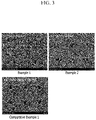
- the negative electrode mixture of the preliminary negative electrode manufactured in Production Example was irradiated once at 100 ⁇ m intervals by using a nanosecond laser (SPI G4, 1064nm) and setting the following conditions to form a plurality of holes, thereby manufacturing a negative electrode
- a negative electrode was manufactured by forming the holes in the same manner in Example 1, except that the interval between the holes was set to 200 ⁇ m.
- a negative electrode was manufactured by forming the holes in the same manner in Example 1, except that the interval between the holes was set to 200 ⁇ m and irradiation was performed 3 times to form a large number of holes
- FIG. 3 Plan-view SEM images of the positive electrodes manufactured in Examples 1 to 2 and Comparative Example 1 were taken, and shown in FIG. 3 .
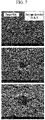
- the hole depth and the hole diameter (diameter on a plane) were measured with a non-contact optical profiler, and the results are shown in FIG. 4 .
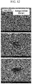
- the distribution diagram of the hole depth and the hole diameter is shown in FIG. 5 below.
- a negative electrode was manufactured by forming the holes in the same manner in Example 1, except that the interval between the holes was set to 500 ⁇ m.
- a negative electrode was manufactured by forming the holes in the same manner in Example 1, except that the interval between the holes was set to 500 ⁇ m and the average power of the laser was set to 40W (80%).
- a negative electrode was manufactured by forming the holes in the same manner in Example 1, except that the interval between the holes was set to 500 ⁇ m and the average power of the laser was set to 30W (60%).
- a negative electrode was manufactured by forming the holes in the same manner in Example 1, except that the interval between the holes was set to 500 ⁇ m and the average power of the laser was set to 20W (40%).
- the negative electrode mixture of the preliminary negative electrode manufactured in the previous Production Example was irradiated once at 100 ⁇ m intervals by using a picosecond laser (TruMicro 5050, 1030nm) and setting the following conditions to form a plurality of holes, thereby manufacturing a negative electrode
- a negative electrode was manufactured by forming the holes in the same manner in Comparative Example 3, except that the average power of the laser was set to 40W (80%).
- a negative electrode was manufactured by forming the holes in the same manner in Comparative Example 3, except that the average power of the laser was set to 30W (60%).
- holes are properly formed with an average diameter of 50 ⁇ m or less, whereas when the average power is too low even if the nanosecond is used, holes are not formed properly. In the case of using the picosecond, the diameter of the hole became larger than 100 ⁇ m, which is thus not appropriate.
- a negative electrode was manufactured by forming the holes in the same manner in Example 1, except that the interval between the holes was set to 150 ⁇ m.
- a negative electrode was manufactured under the same condition in Example 1, except that a nanosecond laser was used to form line-shaped grooves instead of holes, and the interval was set to 100 ⁇ m.
- a negative electrode was manufactured under the same condition in Example 1, except that a nanosecond laser was used to form line-shaped grooves instead of holes, and the interval was set to 150 ⁇ m.
- a negative electrode was manufactured under the same condition in Example 1, except that a nanosecond laser was used to form line-shaped grooves instead of holes and the interval was set to 200 ⁇ m.
- the reduction rate of the loading amount was measured for the negative electrode of Examples 1, 2, 6, and Comparative Examples 6 to 8 to compare the case where the hole was formed and the case where the line-shaped groove was formed, and is shown in FIG. 13 .
- the reduction rate of the loading amount was determined by measuring the weight before and after laser treatment, removing the active material, and measuring the weight of the Cu foil, and calculating the equation of (active material weight before laser treatment-active material weight after laser treatment) / active material weight before laser treatment.
- the capacity decreases as the loading amount decreases, which is thus not preferable, and in the case of forming in a hole shape, the reduction in the loading amount is minimized, which is thus preferable.
- the negative electrode (hole average diameter: 50 ⁇ m, hole average depth: 34 ⁇ m) manufactured in Example 1 was used.
- LiCoO 2 was used as an active material
- PVDF and SBRd were used as a binder
- carbon black was used as a conductive material.
- the holes formed in the negative electrode had an average diameter of about 50 ⁇ m and an average depth of about 34 ⁇ m.
- the holes formed in the negative electrode had an average diameter of about 40 ⁇ m and an average depth of about 24 ⁇ m.
- the secondary battery was manufactured in the same manner as in Example 7, except that the negative electrode manufactured in Comparative Example 1 was used. Three batteries were prepared.
- the holes formed in the negative electrode had an average diameter of about 60 ⁇ m and an average depth of about 26 ⁇ m.
- the secondary battery was manufactured in the same manner as in Example 7, except for using the preliminary negative electrode having no holes formed herein manufactured in the previous Production Example. Three batteries were prepared.
- the secondary batteries manufactured in Examples 7, 8 and Comparative Examples 9 and 10 were charged at 1C up to 4.2V under constant current/constant voltage (CC/CV) conditions, and then discharged at 1/3C up to 3.4 V under constant current (CC) conditions.
- the discharge capacity was measured, and the results are shown in FIG. 14 below.
- the secondary batteries manufactured in Examples 7, 8 and Comparative Example 10 were sampled, and charged at 1/3C, 1/2C, 1C, 1.5C, 2C up to 4.2V under constant current/constant voltage (CC/CV) conditions, respectively, and then discharged at 1/3C up to 3.4 V under the constant current (CC) condition.
- CC/CV constant current/constant voltage
- the discharge capacity according to C-rate was measured, and the results are shown in FIG. 15 below.
Landscapes
- Engineering & Computer Science (AREA)
- Chemical & Material Sciences (AREA)
- Optics & Photonics (AREA)
- Physics & Mathematics (AREA)
- General Chemical & Material Sciences (AREA)
- Chemical Kinetics & Catalysis (AREA)
- Electrochemistry (AREA)
- Manufacturing & Machinery (AREA)
- Mechanical Engineering (AREA)
- Plasma & Fusion (AREA)
- Materials Engineering (AREA)
- Battery Electrode And Active Subsutance (AREA)
- Cell Electrode Carriers And Collectors (AREA)
Applications Claiming Priority (2)
| Application Number | Priority Date | Filing Date | Title |
|---|---|---|---|
| KR1020190173412A KR102807488B1 (ko) | 2019-12-23 | 2019-12-23 | 레이저를 이용한 이차전지용 전극의 제조장치와 제조방법, 및 이에 의해 제조된 이차전지용 전극 |
| PCT/KR2020/012512 WO2021132848A1 (fr) | 2019-12-23 | 2020-09-16 | Procédé et appareil de fabrication d'électrode pour batterie auxiliaire utilisant un laser et électrode pour batterie auxiliaire fabriquée par ceux-ci |
Publications (3)
| Publication Number | Publication Date |
|---|---|
| EP4016665A1 true EP4016665A1 (fr) | 2022-06-22 |
| EP4016665A4 EP4016665A4 (fr) | 2023-09-13 |
| EP4016665B1 EP4016665B1 (fr) | 2024-10-30 |
Family
ID=76574847
Family Applications (1)
| Application Number | Title | Priority Date | Filing Date |
|---|---|---|---|
| EP20907522.5A Active EP4016665B1 (fr) | 2019-12-23 | 2020-09-16 | Procédé et appareil de fabrication d'électrode pour batterie auxiliaire utilisant un laser et électrode pour batterie auxiliaire fabriquée par ceux-ci |
Country Status (7)
| Country | Link |
|---|---|
| US (1) | US12476240B2 (fr) |
| EP (1) | EP4016665B1 (fr) |
| KR (1) | KR102807488B1 (fr) |
| CN (1) | CN114365306B (fr) |
| ES (1) | ES3005033T3 (fr) |
| HU (1) | HUE069508T2 (fr) |
| WO (1) | WO2021132848A1 (fr) |
Cited By (4)
| Publication number | Priority date | Publication date | Assignee | Title |
|---|---|---|---|---|
| SE2250839A1 (en) * | 2022-07-04 | 2024-01-05 | Northvolt Ab | Electrode for a secondary cell |
| SE2250838A1 (en) * | 2022-07-04 | 2024-01-05 | Northvolt Ab | Electrode for a secondary cell |
| EP4386880A1 (fr) * | 2022-12-14 | 2024-06-19 | Siemens Aktiengesellschaft | Procédé et dispositif de séchage d'un matériau d'électrode de fabrication d'élément de batterie |
| SE2350963A1 (en) * | 2023-08-15 | 2025-02-16 | Northvolt Ab | Secondary cell with a molded hybrid electrode |
Families Citing this family (10)
| Publication number | Priority date | Publication date | Assignee | Title |
|---|---|---|---|---|
| US12533703B2 (en) * | 2020-11-11 | 2026-01-27 | Panasonic Intellectual Property Management Co., Ltd. | Electrode mixture slurry coating device |
| KR20230064384A (ko) * | 2021-11-03 | 2023-05-10 | 주식회사 엘지에너지솔루션 | 전극 식각 장치 |
| JP7403887B1 (ja) * | 2023-01-31 | 2023-12-25 | オー・エム・シー株式会社 | 二次電池の塗工膜の乾燥方法とその塗工装置 |
| KR102925407B1 (ko) | 2023-05-18 | 2026-02-10 | 서울엔지니어링(주) | 이차전지 전극탭 형성을 위한 레이저 어블레이션 장치 |
| KR20250003217A (ko) * | 2023-06-30 | 2025-01-07 | 삼성에스디아이 주식회사 | 리튬 이차 전지용 전극 및 이를 포함하는 리튬 이차 전지 |
| JP2025039385A (ja) * | 2023-09-08 | 2025-03-21 | トヨタ自動車株式会社 | 電池用活物質層の製造方法、電池用活物質層、及び電池 |
| KR20250107514A (ko) | 2024-01-05 | 2025-07-14 | 주식회사 엘지에너지솔루션 | 이차 전지 제조 설비 및 이차 전지를 제조하는 방법 |
| KR20260024736A (ko) * | 2024-08-14 | 2026-02-23 | 주식회사 엘지에너지솔루션 | 음극 제조방법, 음극 제조장치 및 이를 이용하여 제조된 이차전지 |
| CN119407482A (zh) * | 2024-11-02 | 2025-02-11 | 北京工业大学 | 一种基于飞秒激光的镁电极表面加工方法 |
| CN119973383B (zh) * | 2025-02-24 | 2025-10-03 | 广东海洋大学 | 低温轧制后高频脉冲纳秒激光表面重熔的铝合金强化方法 |
Family Cites Families (30)
| Publication number | Priority date | Publication date | Assignee | Title |
|---|---|---|---|---|
| JPH09283116A (ja) | 1996-04-11 | 1997-10-31 | Sumitomo Electric Ind Ltd | 非水電解質二次電池 |
| KR100398173B1 (ko) | 2001-02-06 | 2003-09-19 | 주식회사 엘지화학 | 천공된 전극군 및 이를 이용하는 리튬 2차 전지 |
| SG173372A1 (en) * | 2006-07-18 | 2011-08-29 | Cymbet Corp | Method and apparatus for solid-state microbattery photolithographic manufacture, singulation and passivation |
| JP5826027B2 (ja) * | 2008-03-21 | 2015-12-02 | イムラ アメリカ インコーポレイテッド | レーザベースの材料加工方法及びシステム |
| CN102405544B (zh) * | 2009-04-22 | 2015-06-10 | 丰田自动车株式会社 | 电池用电极的制造方法以及用于其中的涂布模具 |
| KR101264742B1 (ko) * | 2011-08-03 | 2013-05-14 | 삼성에스디아이 주식회사 | 전극판 형성 장치 |
| JP2013097925A (ja) * | 2011-10-28 | 2013-05-20 | Sanyo Electric Co Ltd | リチウム二次電池の電極の製造方法、リチウム二次電池の電極及びリチウム二次電池 |
| CN103258986B (zh) | 2012-02-21 | 2017-08-08 | 精工爱普生株式会社 | 电极活性物质层的制造方法 |
| JP5948941B2 (ja) | 2012-02-21 | 2016-07-06 | セイコーエプソン株式会社 | 電極活物質層の製造方法、電極活物質層、電極体およびリチウムイオン二次電池 |
| KR20130101174A (ko) * | 2012-03-05 | 2013-09-13 | 주식회사 엘지화학 | 신규한 구조의 이차전지용 전극 건조장치 |
| KR20130102711A (ko) | 2012-03-08 | 2013-09-23 | 주식회사 엘지화학 | 이차전지용 전극 가공장치 |
| KR101483422B1 (ko) * | 2012-05-21 | 2015-01-16 | 주식회사 엘지화학 | 레이저 조사에 의한 전극단자의 표면처리 방법 |
| TWI612712B (zh) | 2012-10-25 | 2018-01-21 | 應用材料股份有限公司 | 繞射光學元件及用於圖案化薄膜電化學元件的方法 |
| CN103094521A (zh) * | 2013-01-22 | 2013-05-08 | 宁德时代新能源科技有限公司 | 锂离子动力电池正极片及其制造方法、激光蚀刻装置 |
| KR20150082958A (ko) * | 2014-01-08 | 2015-07-16 | 주식회사 엘지화학 | 이차전지용 전극 및 그 제조방법 |
| CN203932198U (zh) | 2014-05-30 | 2014-11-05 | 比亚迪股份有限公司 | 一种锂离子电池电极片及锂离子电池 |
| KR101710654B1 (ko) | 2014-08-01 | 2017-02-27 | 주식회사 엘지화학 | 전해액 주액성이 향상된 리튬이차전지 및 그의 제조방법 |
| CN105374985B (zh) | 2014-08-26 | 2018-01-16 | 万星光电子(东莞)有限公司 | 电极片制备装置以及电极片制备方法 |
| KR102040240B1 (ko) * | 2015-06-04 | 2019-11-04 | 주식회사 엘지화학 | 이차전지용 전극 및 그 제조방법 |
| KR102076502B1 (ko) | 2015-11-18 | 2020-02-12 | 주식회사 엘지화학 | 전극의 표면 형상을 정밀하게 성형할 수 있는 장치 |
| KR20170068064A (ko) | 2015-12-09 | 2017-06-19 | 주식회사 엘지화학 | 전극의 식각 방법 및 상기 식각 방법으로 식각된 전극을 포함하는 이차 전지 |
| KR102168229B1 (ko) | 2016-02-12 | 2020-10-20 | 주식회사 엘지화학 | 전기화학소자용 전극 및 상기 전극을 제조하는 방법 |
| JP7058838B2 (ja) | 2016-03-16 | 2022-04-25 | エルジー エナジー ソリューション リミテッド | 二層構造の電極及びその製造方法 |
| US20170301897A1 (en) * | 2016-04-14 | 2017-10-19 | Applied Materials, Inc. | Thin film device encapsulation using volume change accommodating materials |
| KR102207524B1 (ko) | 2016-09-01 | 2021-01-26 | 주식회사 엘지화학 | 리튬 이차전지용 전극의 제조방법 및 이로부터 제조된 리튬 이차전지용 전극 |
| DE102017202679A1 (de) * | 2017-02-20 | 2018-08-23 | Fraunhofer-Gesellschaft zur Förderung der angewandten Forschung e.V. | Bipolarplatte für elektrochemische Zellen sowie ein Herstellungsverfahren |
| JP2018160349A (ja) * | 2017-03-22 | 2018-10-11 | 三菱マテリアル株式会社 | 蓄電デバイス |
| US10622621B2 (en) | 2017-03-31 | 2020-04-14 | GM Global Technology Operations LLC | Methods for making patterned, thick, silicon-containing electrodes |
| WO2019163896A1 (fr) * | 2018-02-22 | 2019-08-29 | Jsr株式会社 | Dispositif de stockage d'énergie, électrode de dispositif de stockage d'énergie, et procédé de fabrication dudit dispositif de stockage d'énergie et électrode de dispositif de stockage d'énergie |
| KR102086783B1 (ko) * | 2019-03-27 | 2020-03-09 | 광주과학기술원 | 리튬 이차 전지용 후막 전극 및 리튬 이차 전지 |
-
2019
- 2019-12-23 KR KR1020190173412A patent/KR102807488B1/ko active Active
-
2020
- 2020-09-16 WO PCT/KR2020/012512 patent/WO2021132848A1/fr not_active Ceased
- 2020-09-16 ES ES20907522T patent/ES3005033T3/es active Active
- 2020-09-16 US US17/640,962 patent/US12476240B2/en active Active
- 2020-09-16 HU HUE20907522A patent/HUE069508T2/hu unknown
- 2020-09-16 CN CN202080060049.XA patent/CN114365306B/zh active Active
- 2020-09-16 EP EP20907522.5A patent/EP4016665B1/fr active Active
Cited By (4)
| Publication number | Priority date | Publication date | Assignee | Title |
|---|---|---|---|---|
| SE2250839A1 (en) * | 2022-07-04 | 2024-01-05 | Northvolt Ab | Electrode for a secondary cell |
| SE2250838A1 (en) * | 2022-07-04 | 2024-01-05 | Northvolt Ab | Electrode for a secondary cell |
| EP4386880A1 (fr) * | 2022-12-14 | 2024-06-19 | Siemens Aktiengesellschaft | Procédé et dispositif de séchage d'un matériau d'électrode de fabrication d'élément de batterie |
| SE2350963A1 (en) * | 2023-08-15 | 2025-02-16 | Northvolt Ab | Secondary cell with a molded hybrid electrode |
Also Published As
| Publication number | Publication date |
|---|---|
| US20220344632A1 (en) | 2022-10-27 |
| CN114365306A (zh) | 2022-04-15 |
| HUE069508T2 (hu) | 2025-03-28 |
| KR20210081155A (ko) | 2021-07-01 |
| ES3005033T3 (en) | 2025-03-13 |
| US12476240B2 (en) | 2025-11-18 |
| KR102807488B1 (ko) | 2025-05-13 |
| CN114365306B (zh) | 2024-04-16 |
| WO2021132848A1 (fr) | 2021-07-01 |
| EP4016665B1 (fr) | 2024-10-30 |
| EP4016665A4 (fr) | 2023-09-13 |
Similar Documents
| Publication | Publication Date | Title |
|---|---|---|
| EP4016665B1 (fr) | Procédé et appareil de fabrication d'électrode pour batterie auxiliaire utilisant un laser et électrode pour batterie auxiliaire fabriquée par ceux-ci | |
| US9843045B2 (en) | Negative electrode active material and method for producing the same | |
| KR102373313B1 (ko) | 무기 전해액을 포함하는 리튬 이차전지 | |
| CN108140811B (zh) | 制备锂二次电池用的电极的方法和由此制备的锂二次电池用的电极 | |
| CN108352506B (zh) | 正极和包含该正极的二次电池 | |
| JP7164123B2 (ja) | 負極活物質、前記負極活物質を含む負極、及び前記負極を含む二次電池 | |
| US20150236343A1 (en) | Coated electrodes for lithium batteries | |
| JP7270833B2 (ja) | 高ニッケル電極シートおよびその製造方法 | |
| CN106663815B (zh) | 制造导电材料的方法、由此制造的导电材料和包含所述导电材料的锂二次电池 | |
| KR102536633B1 (ko) | 양극의 제조 방법 | |
| KR20200085587A (ko) | 음극 및 이를 포함하는 이차전지 | |
| JP7614227B2 (ja) | 二次電池 | |
| CN113272996A (zh) | 制造用于二次电池的负极的方法 | |
| CN115004405B (zh) | 制造二次电池的方法 | |
| KR20160113981A (ko) | 음극 활물질 및 이의 제조방법 | |
| CN113646946A (zh) | 二次电池 | |
| EP4207349A1 (fr) | Électrode négative et batterie secondaire la comprenant | |
| CN117693831A (zh) | 负极组合物、锂二次电池用负极以及包含负极的锂二次电池 | |
| US20260045514A1 (en) | Electrode and Method for Manufacturing Electrode | |
| JP2009199973A (ja) | 非水系二次電池用集電体およびこれを用いた非水系二次電池用電極板と非水系二次電池 | |
| JP7313637B2 (ja) | 安全性向上のために硬化度が増加した正極、その製造方法、およびこれを含む二次電池 | |
| JP7580847B2 (ja) | 負極の製造方法 | |
| EP4418395A1 (fr) | Procédé de fabrication d'ensemble électrode, ensemble électrode et batterie secondaire au lithium le comprenant | |
| KR102962581B1 (ko) | 패턴이 형성된 리튬-황 이차전지용 양극의 제조방법 및 이를 포함하는 리튬-황 이차전지의 제조방법 | |
| KR102364480B1 (ko) | 음극 활물질, 상기 음극 활물질을 포함하는 음극, 및 상기 음극을 포함하는 리튬 이차 전지 |
Legal Events
| Date | Code | Title | Description |
|---|---|---|---|
| STAA | Information on the status of an ep patent application or granted ep patent |
Free format text: STATUS: THE INTERNATIONAL PUBLICATION HAS BEEN MADE |
|
| PUAI | Public reference made under article 153(3) epc to a published international application that has entered the european phase |
Free format text: ORIGINAL CODE: 0009012 |
|
| STAA | Information on the status of an ep patent application or granted ep patent |
Free format text: STATUS: REQUEST FOR EXAMINATION WAS MADE |
|
| 17P | Request for examination filed |
Effective date: 20220317 |
|
| AK | Designated contracting states |
Kind code of ref document: A1 Designated state(s): AL AT BE BG CH CY CZ DE DK EE ES FI FR GB GR HR HU IE IS IT LI LT LU LV MC MK MT NL NO PL PT RO RS SE SI SK SM TR |
|
| DAV | Request for validation of the european patent (deleted) | ||
| DAX | Request for extension of the european patent (deleted) | ||
| A4 | Supplementary search report drawn up and despatched |
Effective date: 20230810 |
|
| RIC1 | Information provided on ipc code assigned before grant |
Ipc: H01M 4/02 20060101ALI20230804BHEP Ipc: H01M 4/139 20100101ALI20230804BHEP Ipc: H01M 4/13 20100101ALI20230804BHEP Ipc: B23K 103/16 20060101ALI20230804BHEP Ipc: B23K 101/36 20060101ALI20230804BHEP Ipc: B23K 26/402 20140101ALI20230804BHEP Ipc: B23K 26/386 20140101ALI20230804BHEP Ipc: B23K 26/08 20140101ALI20230804BHEP Ipc: B23K 26/082 20140101ALI20230804BHEP Ipc: B23K 26/0622 20140101ALI20230804BHEP Ipc: B23K 26/362 20140101ALI20230804BHEP Ipc: B23K 26/382 20140101ALI20230804BHEP Ipc: H01M 4/04 20060101AFI20230804BHEP |
|
| GRAP | Despatch of communication of intention to grant a patent |
Free format text: ORIGINAL CODE: EPIDOSNIGR1 |
|
| STAA | Information on the status of an ep patent application or granted ep patent |
Free format text: STATUS: GRANT OF PATENT IS INTENDED |
|
| INTG | Intention to grant announced |
Effective date: 20240621 |
|
| P01 | Opt-out of the competence of the unified patent court (upc) registered |
Free format text: CASE NUMBER: APP_39354/2024 Effective date: 20240702 |
|
| GRAS | Grant fee paid |
Free format text: ORIGINAL CODE: EPIDOSNIGR3 |
|
| GRAA | (expected) grant |
Free format text: ORIGINAL CODE: 0009210 |
|
| STAA | Information on the status of an ep patent application or granted ep patent |
Free format text: STATUS: THE PATENT HAS BEEN GRANTED |
|
| AK | Designated contracting states |
Kind code of ref document: B1 Designated state(s): AL AT BE BG CH CY CZ DE DK EE ES FI FR GB GR HR HU IE IS IT LI LT LU LV MC MK MT NL NO PL PT RO RS SE SI SK SM TR |
|
| REG | Reference to a national code |
Ref country code: GB Ref legal event code: FG4D |
|
| REG | Reference to a national code |
Ref country code: CH Ref legal event code: EP |
|
| REG | Reference to a national code |
Ref country code: IE Ref legal event code: FG4D |
|
| REG | Reference to a national code |
Ref country code: DE Ref legal event code: R096 Ref document number: 602020040579 Country of ref document: DE |
|
| REG | Reference to a national code |
Ref country code: LT Ref legal event code: MG9D |
|
| REG | Reference to a national code |
Ref country code: NL Ref legal event code: MP Effective date: 20241030 |
|
| REG | Reference to a national code |
Ref country code: ES Ref legal event code: FG2A Ref document number: 3005033 Country of ref document: ES Kind code of ref document: T3 Effective date: 20250313 |
|
| REG | Reference to a national code |
Ref country code: HU Ref legal event code: AG4A Ref document number: E069508 Country of ref document: HU |
|
| PG25 | Lapsed in a contracting state [announced via postgrant information from national office to epo] |
Ref country code: PT Free format text: LAPSE BECAUSE OF FAILURE TO SUBMIT A TRANSLATION OF THE DESCRIPTION OR TO PAY THE FEE WITHIN THE PRESCRIBED TIME-LIMIT Effective date: 20250228 Ref country code: HR Free format text: LAPSE BECAUSE OF FAILURE TO SUBMIT A TRANSLATION OF THE DESCRIPTION OR TO PAY THE FEE WITHIN THE PRESCRIBED TIME-LIMIT Effective date: 20241030 Ref country code: IS Free format text: LAPSE BECAUSE OF FAILURE TO SUBMIT A TRANSLATION OF THE DESCRIPTION OR TO PAY THE FEE WITHIN THE PRESCRIBED TIME-LIMIT Effective date: 20250228 |
|
| PG25 | Lapsed in a contracting state [announced via postgrant information from national office to epo] |
Ref country code: FI Free format text: LAPSE BECAUSE OF FAILURE TO SUBMIT A TRANSLATION OF THE DESCRIPTION OR TO PAY THE FEE WITHIN THE PRESCRIBED TIME-LIMIT Effective date: 20241030 Ref country code: NL Free format text: LAPSE BECAUSE OF FAILURE TO SUBMIT A TRANSLATION OF THE DESCRIPTION OR TO PAY THE FEE WITHIN THE PRESCRIBED TIME-LIMIT Effective date: 20241030 |
|
| REG | Reference to a national code |
Ref country code: AT Ref legal event code: MK05 Ref document number: 1737824 Country of ref document: AT Kind code of ref document: T Effective date: 20241030 |
|
| PG25 | Lapsed in a contracting state [announced via postgrant information from national office to epo] |
Ref country code: BG Free format text: LAPSE BECAUSE OF FAILURE TO SUBMIT A TRANSLATION OF THE DESCRIPTION OR TO PAY THE FEE WITHIN THE PRESCRIBED TIME-LIMIT Effective date: 20241030 |
|
| PG25 | Lapsed in a contracting state [announced via postgrant information from national office to epo] |
Ref country code: NO Free format text: LAPSE BECAUSE OF FAILURE TO SUBMIT A TRANSLATION OF THE DESCRIPTION OR TO PAY THE FEE WITHIN THE PRESCRIBED TIME-LIMIT Effective date: 20250130 |
|
| PG25 | Lapsed in a contracting state [announced via postgrant information from national office to epo] |
Ref country code: AT Free format text: LAPSE BECAUSE OF FAILURE TO SUBMIT A TRANSLATION OF THE DESCRIPTION OR TO PAY THE FEE WITHIN THE PRESCRIBED TIME-LIMIT Effective date: 20241030 Ref country code: LV Free format text: LAPSE BECAUSE OF FAILURE TO SUBMIT A TRANSLATION OF THE DESCRIPTION OR TO PAY THE FEE WITHIN THE PRESCRIBED TIME-LIMIT Effective date: 20241030 Ref country code: GR Free format text: LAPSE BECAUSE OF FAILURE TO SUBMIT A TRANSLATION OF THE DESCRIPTION OR TO PAY THE FEE WITHIN THE PRESCRIBED TIME-LIMIT Effective date: 20250131 |
|
| PG25 | Lapsed in a contracting state [announced via postgrant information from national office to epo] |
Ref country code: PL Free format text: LAPSE BECAUSE OF FAILURE TO SUBMIT A TRANSLATION OF THE DESCRIPTION OR TO PAY THE FEE WITHIN THE PRESCRIBED TIME-LIMIT Effective date: 20241030 |
|
| PG25 | Lapsed in a contracting state [announced via postgrant information from national office to epo] |
Ref country code: RS Free format text: LAPSE BECAUSE OF FAILURE TO SUBMIT A TRANSLATION OF THE DESCRIPTION OR TO PAY THE FEE WITHIN THE PRESCRIBED TIME-LIMIT Effective date: 20250130 |
|
| PG25 | Lapsed in a contracting state [announced via postgrant information from national office to epo] |
Ref country code: SM Free format text: LAPSE BECAUSE OF FAILURE TO SUBMIT A TRANSLATION OF THE DESCRIPTION OR TO PAY THE FEE WITHIN THE PRESCRIBED TIME-LIMIT Effective date: 20241030 |
|
| PG25 | Lapsed in a contracting state [announced via postgrant information from national office to epo] |
Ref country code: DK Free format text: LAPSE BECAUSE OF FAILURE TO SUBMIT A TRANSLATION OF THE DESCRIPTION OR TO PAY THE FEE WITHIN THE PRESCRIBED TIME-LIMIT Effective date: 20241030 |
|
| PGFP | Annual fee paid to national office [announced via postgrant information from national office to epo] |
Ref country code: BE Payment date: 20250407 Year of fee payment: 6 |
|
| PG25 | Lapsed in a contracting state [announced via postgrant information from national office to epo] |
Ref country code: EE Free format text: LAPSE BECAUSE OF FAILURE TO SUBMIT A TRANSLATION OF THE DESCRIPTION OR TO PAY THE FEE WITHIN THE PRESCRIBED TIME-LIMIT Effective date: 20241030 |
|
| PG25 | Lapsed in a contracting state [announced via postgrant information from national office to epo] |
Ref country code: RO Free format text: LAPSE BECAUSE OF FAILURE TO SUBMIT A TRANSLATION OF THE DESCRIPTION OR TO PAY THE FEE WITHIN THE PRESCRIBED TIME-LIMIT Effective date: 20241030 |
|
| PG25 | Lapsed in a contracting state [announced via postgrant information from national office to epo] |
Ref country code: SK Free format text: LAPSE BECAUSE OF FAILURE TO SUBMIT A TRANSLATION OF THE DESCRIPTION OR TO PAY THE FEE WITHIN THE PRESCRIBED TIME-LIMIT Effective date: 20241030 |
|
| PG25 | Lapsed in a contracting state [announced via postgrant information from national office to epo] |
Ref country code: CZ Free format text: LAPSE BECAUSE OF FAILURE TO SUBMIT A TRANSLATION OF THE DESCRIPTION OR TO PAY THE FEE WITHIN THE PRESCRIBED TIME-LIMIT Effective date: 20241030 |
|
| PG25 | Lapsed in a contracting state [announced via postgrant information from national office to epo] |
Ref country code: IT Free format text: LAPSE BECAUSE OF FAILURE TO SUBMIT A TRANSLATION OF THE DESCRIPTION OR TO PAY THE FEE WITHIN THE PRESCRIBED TIME-LIMIT Effective date: 20241030 |
|
| REG | Reference to a national code |
Ref country code: DE Ref legal event code: R097 Ref document number: 602020040579 Country of ref document: DE |
|
| PLBE | No opposition filed within time limit |
Free format text: ORIGINAL CODE: 0009261 |
|
| STAA | Information on the status of an ep patent application or granted ep patent |
Free format text: STATUS: NO OPPOSITION FILED WITHIN TIME LIMIT |
|
| PG25 | Lapsed in a contracting state [announced via postgrant information from national office to epo] |
Ref country code: SE Free format text: LAPSE BECAUSE OF FAILURE TO SUBMIT A TRANSLATION OF THE DESCRIPTION OR TO PAY THE FEE WITHIN THE PRESCRIBED TIME-LIMIT Effective date: 20241030 |
|
| 26N | No opposition filed |
Effective date: 20250731 |
|
| PGFP | Annual fee paid to national office [announced via postgrant information from national office to epo] |
Ref country code: DE Payment date: 20250820 Year of fee payment: 6 |
|
| PGFP | Annual fee paid to national office [announced via postgrant information from national office to epo] |
Ref country code: HU Payment date: 20250929 Year of fee payment: 6 Ref country code: GB Payment date: 20250820 Year of fee payment: 6 |
|
| PGFP | Annual fee paid to national office [announced via postgrant information from national office to epo] |
Ref country code: FR Payment date: 20250821 Year of fee payment: 6 |
|
| PGFP | Annual fee paid to national office [announced via postgrant information from national office to epo] |
Ref country code: ES Payment date: 20251007 Year of fee payment: 6 |