EP4016766A1 - Système d'armoire électrique - Google Patents
Système d'armoire électrique Download PDFInfo
- Publication number
- EP4016766A1 EP4016766A1 EP21215396.9A EP21215396A EP4016766A1 EP 4016766 A1 EP4016766 A1 EP 4016766A1 EP 21215396 A EP21215396 A EP 21215396A EP 4016766 A1 EP4016766 A1 EP 4016766A1
- Authority
- EP
- European Patent Office
- Prior art keywords
- housing
- opening
- control cabinet
- wall
- device housing
- Prior art date
- Legal status (The legal status is an assumption and is not a legal conclusion. Google has not performed a legal analysis and makes no representation as to the accuracy of the status listed.)
- Pending
Links
- 238000007689 inspection Methods 0.000 claims description 19
- 239000007788 liquid Substances 0.000 claims description 14
- 239000012530 fluid Substances 0.000 claims description 8
- 239000007789 gas Substances 0.000 claims description 7
- 239000002826 coolant Substances 0.000 claims description 5
- 239000000428 dust Substances 0.000 claims description 3
- 238000007789 sealing Methods 0.000 claims description 2
- 230000035515 penetration Effects 0.000 claims 1
- 238000006243 chemical reaction Methods 0.000 description 7
- 238000011161 development Methods 0.000 description 3
- 230000009977 dual effect Effects 0.000 description 3
- 238000009434 installation Methods 0.000 description 3
- 238000012423 maintenance Methods 0.000 description 2
- 238000012360 testing method Methods 0.000 description 2
- 230000000295 complement effect Effects 0.000 description 1
- 238000010276 construction Methods 0.000 description 1
- 238000001816 cooling Methods 0.000 description 1
- 230000001419 dependent effect Effects 0.000 description 1
- 238000013461 design Methods 0.000 description 1
- 238000006073 displacement reaction Methods 0.000 description 1
- 238000010616 electrical installation Methods 0.000 description 1
- 230000009969 flowable effect Effects 0.000 description 1
- 239000010720 hydraulic oil Substances 0.000 description 1
- 239000000314 lubricant Substances 0.000 description 1
- 238000000034 method Methods 0.000 description 1
- 238000000926 separation method Methods 0.000 description 1
- 239000007787 solid Substances 0.000 description 1
Images


Classifications
-
- H—ELECTRICITY
- H02—GENERATION; CONVERSION OR DISTRIBUTION OF ELECTRIC POWER
- H02B—BOARDS, SUBSTATIONS OR SWITCHING ARRANGEMENTS FOR THE SUPPLY OR DISTRIBUTION OF ELECTRIC POWER
- H02B1/00—Frameworks, boards, panels, desks, casings; Details of substations or switching arrangements
- H02B1/26—Casings; Parts thereof or accessories therefor
- H02B1/30—Cabinet-type casings; Parts thereof or accessories therefor
- H02B1/38—Hinged covers or doors
-
- H—ELECTRICITY
- H02—GENERATION; CONVERSION OR DISTRIBUTION OF ELECTRIC POWER
- H02B—BOARDS, SUBSTATIONS OR SWITCHING ARRANGEMENTS FOR THE SUPPLY OR DISTRIBUTION OF ELECTRIC POWER
- H02B1/00—Frameworks, boards, panels, desks, casings; Details of substations or switching arrangements
- H02B1/26—Casings; Parts thereof or accessories therefor
- H02B1/30—Cabinet-type casings; Parts thereof or accessories therefor
- H02B1/308—Mounting of cabinets together
-
- H—ELECTRICITY
- H02—GENERATION; CONVERSION OR DISTRIBUTION OF ELECTRIC POWER
- H02B—BOARDS, SUBSTATIONS OR SWITCHING ARRANGEMENTS FOR THE SUPPLY OR DISTRIBUTION OF ELECTRIC POWER
- H02B1/00—Frameworks, boards, panels, desks, casings; Details of substations or switching arrangements
- H02B1/26—Casings; Parts thereof or accessories therefor
- H02B1/30—Cabinet-type casings; Parts thereof or accessories therefor
-
- H—ELECTRICITY
- H02—GENERATION; CONVERSION OR DISTRIBUTION OF ELECTRIC POWER
- H02B—BOARDS, SUBSTATIONS OR SWITCHING ARRANGEMENTS FOR THE SUPPLY OR DISTRIBUTION OF ELECTRIC POWER
- H02B1/00—Frameworks, boards, panels, desks, casings; Details of substations or switching arrangements
- H02B1/26—Casings; Parts thereof or accessories therefor
- H02B1/52—Mobile units, e.g. for work sites
-
- H—ELECTRICITY
- H02—GENERATION; CONVERSION OR DISTRIBUTION OF ELECTRIC POWER
- H02B—BOARDS, SUBSTATIONS OR SWITCHING ARRANGEMENTS FOR THE SUPPLY OR DISTRIBUTION OF ELECTRIC POWER
- H02B1/00—Frameworks, boards, panels, desks, casings; Details of substations or switching arrangements
- H02B1/56—Cooling; Ventilation
- H02B1/565—Cooling; Ventilation for cabinets
-
- H—ELECTRICITY
- H05—ELECTRIC TECHNIQUES NOT OTHERWISE PROVIDED FOR
- H05G—X-RAY TECHNIQUE
- H05G1/00—X-ray apparatus involving X-ray tubes; Circuits therefor
- H05G1/02—Constructional details
-
- H—ELECTRICITY
- H05—ELECTRIC TECHNIQUES NOT OTHERWISE PROVIDED FOR
- H05K—PRINTED CIRCUITS; CASINGS OR CONSTRUCTIONAL DETAILS OF ELECTRIC APPARATUS; MANUFACTURE OF ASSEMBLAGES OF ELECTRICAL COMPONENTS
- H05K5/00—Casings, cabinets or drawers for electric apparatus
- H05K5/06—Hermetically-sealed casings
- H05K5/061—Hermetically-sealed casings sealed by a gasket held between a removable cover and a body, e.g. O-ring, packing
-
- H—ELECTRICITY
- H05—ELECTRIC TECHNIQUES NOT OTHERWISE PROVIDED FOR
- H05K—PRINTED CIRCUITS; CASINGS OR CONSTRUCTIONAL DETAILS OF ELECTRIC APPARATUS; MANUFACTURE OF ASSEMBLAGES OF ELECTRICAL COMPONENTS
- H05K7/00—Constructional details common to different types of electric apparatus
- H05K7/18—Construction of rack or frame
Definitions
- the present invention relates to a switch cabinet for accommodating electrical installations, for joint arrangement with a device housing.
- the electrical equipment (control devices, power packs, contactors, etc.) of devices or machines is usually arranged in housings.
- “Housing” is to be understood here as meaning a device which at least partially, preferably completely, surrounds an interior space with the aim of protecting the space from external influences. Protection can relate to mechanical impacts as well as the ingress of solids, liquids or gases. The suitability of a housing for the desired protection can be indicated by the so-called housing protection class.
- An X-ray inspection device with housing protection class IP 69 K, for example, is particularly well protected against external influences.
- housings for machines and devices are to be simply referred to below as device housings. They are usually provided with an access restriction to protect the operating personnel. This is to ensure that electrically live parts are not accidentally touched or come into contact with liquids and dirt.
- the device housing generally has a housing opening which can be closed by a cover, flap or housing door and through which the interior of the device housing with the electrical components located therein can be reached. If possible, the device housing should be sealed on all sides, and any openings must be arranged and protected in such a way that dangerous live parts cannot be reached from the outside.
- Some devices such as X-ray inspection devices, are operated with fluids (flowable media, for example air/compressed air, hydraulic oil or other liquids). These fluids can serve as lubricants or, more particularly, as coolants to cool an x-ray source. Special care must be taken inside the device housing to avoid contact of the fluids with live parts in order to protect the operating personnel or the prevent short circuits or fires from occurring. As a rule, an attempt is made to arrange the liquid circuits in sections (compartments) within the housing that are strictly (hermetically) separated from the electrical system, whereby the legal regulations or the standards to be observed for this can vary from country to country.
- fluids flowable media, for example air/compressed air, hydraulic oil or other liquids.
- the object of the invention was therefore to offer a modular, expandable, cost-effective housing protection concept for electrical equipment, which enables a scalable level of protection and simple subsequent certification.
- the object is achieved by a switch cabinet according to claim 1, a device housing according to claim 3 or an arrangement according to claim 5. Further advantageous embodiments result from the dependent claims.
- the invention is based on the idea of protecting the electrical equipment present in the device housing against possible contact with fluids. To this could the electrical equipment is accommodated in a spatially separated area within the device housing. According to the invention, the desired protection is further improved in that the electrical equipment is largely or completely removed from the device housing and housed in a separate control cabinet.
- the switch cabinet has a dual function in that it seals the electrical equipment located in its interior from the device housing and also closes the device housing at the same time.
- the switch cabinet according to the invention has a switch cabinet interior that is to be delimited or sealed off from the environment, with the delimitation comprising at least one wall.
- This can be, for example, a rear wall of the switch cabinet, which is preferably flat.
- the wall is preferably immovable relative to the switch cabinet or to the switch cabinet interior. It can be permanently connected to a control cabinet frame or to other parts of the control cabinet housing.
- the switch cabinet is designed to use the wall to close a housing opening in a device housing adjacent to the switch cabinet.
- the housing opening can be provided, for example, on the back of a device housing in order to ensure access to the interior of the housing.
- control cabinet allows, on the one hand, the electrical equipment from the device housing to take over, and on the other hand to close the aforementioned housing opening to the device housing with its wall, which allows access to the remaining components in the device housing when removing the wall or the control cabinet.
- the control cabinet then forms a modular extension of the device housing.
- the above-mentioned housing door which closed the housing opening before the conversion, is replaced by the wall of a control cabinet according to the invention, which can be pivoted or moved relative to the housing opening in order to selectively enable or reliably prevent access to the interior of the housing through the housing opening.
- the wall of the control cabinet In an open position, in which the wall of the control cabinet is removed from the housing opening, the components remaining in the device housing can be reached, for example for installation, maintenance or repair work.
- a closed position in which the wall of the switch cabinet closes the housing opening (preferably hermetically), the wall brings about the desired separation of the components in the device housing from the electrical equipment now arranged in the switch cabinet.
- the wall fulfills a dual function since it seals off or separates both the interior of the housing and the interior of the switch cabinet.
- the aforementioned conversion of a device e.g. to remove electrical equipment from the actual device housing
- the modular expansion of a device housing can then be carried out in a simple manner by removing the housing door and instead providing a control cabinet according to the invention, which from the device housing accommodates electrical components to be moved and at the same time is designed to seal the housing opening in the closed position instead of the housing door.
- the control cabinet is then positioned particularly close to the device housing as an expansion module, and unnecessarily long electrical connections between the control cabinet and device housing are superfluous.
- the wall of the control cabinet which separates the interior of the device housing from the interior of the control cabinet, suitable cable bushings have to enable the electrical connection from the control cabinet in the device housing. It is not necessary to lay cables outside of the housing assembly formed by the device housing and the control cabinet for installation or conversion. Appropriately, the bushings and the contact area between the wall and the device housing are sealed in such a way that the increased safety requirements are met and the passage of dirt or dust or liquid or gases from the device housing through the wall into the room of the adjacent control cabinet is prevented.
- the inventive arrangement of device housing and switch cabinet housing is also characterized in that the switch cabinet itself can remain closed even if it is moved relative to the device housing, for example to release the housing opening.
- the desired protection for the components arranged in the switch cabinet is given regardless of whether the switch cabinet is arranged in the closed position or in the open position.
- At least one electrical connection between the control cabinet and the device housing be made by manually detachable plug connections.
- the control cabinet or its electrical equipment can be easily separated from the device housing, for example to be able to carry out maintenance or repair work.
- the electrical connection is made automatically when the closed position is assumed and is automatically broken when the switch cabinet is moved into the open position. This can be done using suitable two-part, preferably complementary, plug-in connections, the parts of which are arranged on the device housing on the one hand and on the control cabinet on the other hand, and which interact with one another when the closed position is assumed.
- the control cabinet according to the invention is preferably designed to hermetically seal the housing opening of the device housing, in particular against the passage of gases and liquids.
- This can be achieved by the wall of the control cabinet closing the housing opening having suitable means for achieving this seal.
- the wall may have a specific profile, sealing means or fittings adapted to be in the closed position to interact with the device housing in the area of the housing opening.
- clamping means on the control cabinet are also conceivable, which can interact with suitable clamping means on the device housing in order to move the control cabinet with its wall in the closed position against the housing opening and to clamp and/or lock it.
- the control cabinet according to the invention can be designed in different ways to be moved with its wall from the closed position closing the housing opening to the open position releasing the housing opening and back.
- the cabinet could be pivoted about a preferably vertical or horizontal pivot axis, with the wall of the cabinet closing the housing opening in one pivoted position and opening it in another.
- the cabinet could be permanently or detachably fastened to the device housing with hinges.
- the cabinet could have means by which it could be slid in front of or away from the cabinet opening with its wall parallel to that wall, in the manner of a sliding door.
- the cabinet could have or use a guide rail (preferably with an end stop) which allows or controls this movement relative to the device housing or the housing opening. Similar guide means could also be provided for controlled displacement of the cabinet perpendicular to and away from the housing opening.
- the invention also relates to a device housing of the type described above, which is designed to close its housing opening by means of the wall of a switch cabinet according to the invention described above.
- the device housing can be suitable for this purpose, for example, in that the housing opening can be closed either by a housing door provided for the device housing or by the wall of a switch cabinet according to the invention.
- the device housing could have means to specifically interact with the wall of a control cabinet according to the invention in order to be able to assume the closed position.
- the device housing could also be suitable for fixing a control cabinet according to the invention or its rear wall in the closed position on the device housing by means of suitable fittings.
- the arrangement according to the invention comprises a device housing and at least one control cabinet of the type described above and is characterized in that the device housing and the control cabinet are designed to interact with one another in such a way that the wall of the control cabinet closes the housing opening in a targeted manner (and preferably hermetically). can.
- the control cabinet could be attached to the device housing via a hinge so that it can be pivoted relative to the device housing in order to selectively open or close the housing opening.
- Guide rails or other guide means are also conceivable, which control the relative movement of the switch cabinet and device housing between the open position and the closed position.
- the switch cabinet according to the invention can have a switch cabinet opening on one side (preferably opposite the wall), which can be closed in a conventional manner by a switch cabinet door.
- the interior of the control cabinet can be reached through this door, and when the control cabinet door is closed, unauthorized access to the control cabinet is denied.
- the wall of the switch cabinet closing the housing opening preferably forms the rear side thereof, while the switch cabinet door is opposite the wall and forms the front side of the switch cabinet.
- a control cabinet door of a first control cabinet can thus be replaced by the wall or rear wall of a second control cabinet, which is positioned in front of the first control cabinet instead of the control cabinet door of the first control cabinet in order to close it.
- a control cabinet or the arrangement according to the invention of a device housing with the associated control cabinet can be further expanded in a modular or cascade-like manner.
- the (rear) wall of one (front) switch cabinet closes the (front) switch cabinet opening of the adjacent other (rear) switch cabinet, whose switch cabinet door can then be dispensed with.
- control cabinets arranged one behind the other in this way are sealed hermetically with the wall in between, i.e. largely gas and liquid-tight, it is also conceivable to arrange components in a control cabinet that are exposed to liquids or gases, while the adjacent control cabinet accommodates separate electrical equipment, similar to the "device housing - control cabinet" combination described above.
- Said double usability of the door facilitates the modular extension or also reduction of an arrangement according to the invention by one or more (preferably similar) control cabinets.
- the door with which the housing opening of the X-ray inspection device was previously closed can be moved to the front of the additional control cabinet to be provided in order to close the control cabinet opening there.
- the housing opening of the x-ray inspection device is instead closed by the wall of the added control cabinet in a manner according to the invention.
- the door is moved in a corresponding manner to the switch cabinet opening of the foremost switch cabinet, while the intermediate switch cabinet openings of the individual switch cabinets are closed by the wall of the next switch cabinet arranged in front of them.
- control cabinets can be removed from an arrangement according to the invention with a device housing and one or more control cabinets arranged in front of it, with the control cabinet door being attached to the control cabinet opening that is exposed in the process (if at least one control cabinet remains in the arrangement) or the housing opening (if after only the device housing remains after the conversion) can be arranged.
- Such an embodiment with a door that fits both on the housing opening and on a control cabinet opening advantageously reduces the outlay for warehousing and the number of parts to be kept ready, since the door, its seal and the fittings are suitable for both applications.
- An arrangement according to the invention consisting of a device housing and at least one control cabinet interacting with it is preferably designed such that the control cabinet can be locked to the housing in the closed position, i.e. when its wall closes the housing opening, using suitable locking means which can also include a key.
- a key which can also include a key.
- This is preferably a switch cabinet key with which a switch cabinet door can also be locked.
- Several directly adjacent control cabinets one of which closes a control cabinet opening of an immediately adjacent further control cabinet in the manner described above, can also be locked relative to one another by means of such a control cabinet key.
- a key is then practically sufficient, with which both the control cabinet door of the foremost control cabinet and, for example, two adjacent control cabinets and a control cabinet covering the housing opening of the device housing can be locked in the closed position.
- different keys or means of access can be provided, which are linked to different access rights, so that, for example, unlocking or access to the housing opening requires a different key than unlocking or accessing a control cabinet
- the weight of the control cabinets must be safely absorbed.
- the control cabinets could be provided with their own feet or rollers, for example, so that they could be moved or moved relative to the device housing or other control cabinets while standing on the floor.
- a switch cabinet is arranged hanging on the device housing or an adjacent further switch cabinet and can be pivoted relative thereto in the sense of a door, the weight of which is absorbed by the adjacent housing.
- the entire (connected) arrangement is then easier to move, e.g. when changing the installation location, than the device housing with several individually standing switch cabinets.
- the device housing with its rollers or feet must then be designed in such a way that it stands securely together with the switch cabinets it supports, even when one or more switch cabinets are moved to the open position.
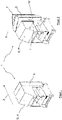
- FIG 1 shows a perspective and simplified representation of an X-ray inspection device R with a device housing G, which rests on a non-illustrated base.
- the device housing G takes in its housing interior I (see figure 2 ) components of the X-ray inspection device R that are not shown in detail, which can include, for example, components that are acted upon by coolant, such as an X-ray tube, a chiller, a dehumidifier, a cooling device, associated pipes or hoses.
- coolant such as an X-ray tube, a chiller, a dehumidifier, a cooling device, associated pipes or hoses.
- a control cabinet S directly adjoins the device housing G.
- the control cabinet S encloses a control cabinet interior M (see figure 3 ), which is intended to accommodate electrical equipment, not shown in detail, that is required for the operation of the X-ray inspection device R is.
- the interior M of the control cabinet S is hermetically separated from the housing interior I of the X-
- control cabinet S On a front side facing away from the wall W and accessible to operating personnel, the control cabinet S is closed by a control cabinet door T, which is in figure 2 and 3 in slightly open position and in figure 4 shown in the closed position.
- the device housing G has a housing opening O G on its rear side facing the control cabinet S, through which the housing interior I is accessible.
- the control cabinet 3 is relative to the device housing G about a vertical pivot axis A between an open position S o and an in figure 4 illustrated closed position S x pivotable.
- the wall W of the switch cabinet closes the housing opening OG completely and hermetically, so that liquid or gaseous coolant, for example, cannot penetrate the environment and in particular the switch cabinet S through the housing opening OG .
- the seal is supported by a seal D which is provided on the edge of the housing opening O G in the device housing and runs around the opening and which is acted upon by the wall W of the switch cabinet S in the closed position.
- the interior of the housing I of the X-ray inspection device R is accessible (the open position So shown is only selected as an example. It does allow access to the interior of the housing I even with the small opening angle shown, but this access can be gained by pivoting the control cabinet S further away from Depending on the design of the connection of the control cabinet S to the device housing G in the area of the pivot axis A, the control cabinet S can also be pivoted by more than 90° from the closed position in order to have almost unhindered access to the interior of the housing I to allow.)
- FIG 3 also shows that the switch cabinet S has a switch cabinet opening Os, which leads into the switch cabinet interior M.
- the switch cabinet opening is opposite the wall W of the switch cabinet and can be closed by the switch cabinet door T.
- the control cabinet door T is arranged on the frame of the control cabinet S in such a way that it can be pivoted relative to the frame of the control cabinet S about a pivot axis A′ parallel to the pivot axis A.
- Both pivot axes A, A' are on the same side of the arrangement, so that (looking at the arrangement from above) both the control cabinet S and its control cabinet door T pivot counterclockwise to open the respective opening O G , O S will.
- the housing opening O G of the X-ray inspection device R has the same dimensions as the control cabinet opening.
- the control cabinet door T is designed to be attached directly to the device housing G instead of to the frame of the control cabinet, so that the housing opening O G - if the control cabinet S can be dispensed with - instead of the wall W of the control cabinet S also with the one from the front Control cabinet S can be closed directly on the device housing offset control cabinet door T.
- the housing opening O G and the control cabinet opening Os are designed in the same way.
- the control cabinet door could also be referred to as a housing door, since it can either close the device housing G or the control cabinet S, depending on how it is installed.
- a housing door previously covering the housing opening O G can also be moved to the front of the control cabinet S after the interposition of a control cabinet S, in order to optionally close or release the control cabinet opening Os there.
- the device housing G can be easily expanded or reduced in a modular way with the help of the control cabinet S.
- An X-ray inspection device R initially designed without an additional control cabinet S can be easily converted by arranging the control cabinet S in the manner shown, for example to relocate certain components from the housing interior I of the X-ray inspection device R to the adjacent control cabinet S and thereby separated from the interior of the housing.
- the control cabinet S is arranged on the device housing according to the invention in such a way that it separates the housing interior I from the control cabinet interior M with its wall W in the closed position.
- the wall W fulfills a dual function, since it seals off or separates both the interior of the housing and the interior of the control cabinet.
- FIG 5 shows a development of the idea on which the invention is based in a simplified representation.
- a device housing G has been expanded to include a control cabinet S in the manner already described.
- the arrangement of device housing G and control cabinet S was supplemented by two more control cabinets S 1 and S 2 .
- the control cabinet S closes the housing opening O G of the device housing G with its wall W in a manner according to the invention (the covered openings or walls in figure 5 cannot be seen).
- the next control cabinet S 1 that is still added closes the control cabinet opening of the control cabinet S with its rear wall in accordance with the invention, while the control cabinet S 2 that is still added in turn closes the control cabinet opening of the first control cabinet S 1 .
- the control cabinet S 2 is closed on its front side with a control cabinet door T.
- All control cabinets can be pivoted relative to each other about a vertical pivot axis, not shown in detail, so that the control cabinet interiors of the individual control cabinets or the housing interior of the device housing I become accessible by the control cabinets arranged in front of the relevant opening being pivoted to the side.
Landscapes
- Engineering & Computer Science (AREA)
- Power Engineering (AREA)
- Casings For Electric Apparatus (AREA)
- Analysing Materials By The Use Of Radiation (AREA)
Applications Claiming Priority (1)
| Application Number | Priority Date | Filing Date | Title |
|---|---|---|---|
| DE102020134288.8A DE102020134288A1 (de) | 2020-12-18 | 2020-12-18 | Schaltschrankanordnung |
Publications (1)
| Publication Number | Publication Date |
|---|---|
| EP4016766A1 true EP4016766A1 (fr) | 2022-06-22 |
Family
ID=78957204
Family Applications (1)
| Application Number | Title | Priority Date | Filing Date |
|---|---|---|---|
| EP21215396.9A Pending EP4016766A1 (fr) | 2020-12-18 | 2021-12-17 | Système d'armoire électrique |
Country Status (6)
| Country | Link |
|---|---|
| US (1) | US11862947B2 (fr) |
| EP (1) | EP4016766A1 (fr) |
| JP (1) | JP7280341B2 (fr) |
| CN (1) | CN114243490B (fr) |
| CA (1) | CA3143063C (fr) |
| DE (1) | DE102020134288A1 (fr) |
Families Citing this family (5)
| Publication number | Priority date | Publication date | Assignee | Title |
|---|---|---|---|---|
| US12221810B2 (en) * | 2021-07-09 | 2025-02-11 | Hoffman Enclosures Inc. | Apparatus and methods for securing an equipment cabinet |
| US12464675B2 (en) | 2021-11-09 | 2025-11-04 | Hoffman Enclosures Inc. | Controlling high density liquid cooling system to liquid cool components |
| CN116093763B (zh) * | 2022-11-30 | 2024-07-12 | 广东省顺德开关厂有限公司 | 一种防水式自降温型箱变 |
| CN117559241B (zh) * | 2023-11-10 | 2024-06-07 | 江苏蓝博自动化科技有限公司 | 一种用于可降解餐具纸浆配浆系统的低压控制柜及方法 |
| CN120453887B (zh) * | 2025-06-04 | 2026-02-17 | 镇江春卓电气有限公司 | 一种智能型电力开关柜 |
Citations (5)
| Publication number | Priority date | Publication date | Assignee | Title |
|---|---|---|---|---|
| DE389017C (de) * | 1923-05-01 | 1924-01-24 | Kurt August Sterzel Dr Ing | Roentgeneinrichtung mit von fluessigem Isoliermittel umgebener Roentgenroehre |
| EP0748017A2 (fr) * | 1995-06-08 | 1996-12-11 | SIFE INDUSTRIALE S.p.A. | Armoire pour équipement électrique avec des compartiments |
| AT2350U1 (de) * | 1996-06-10 | 1998-08-25 | Murtac Mess Und Regeltechnik A | Bedienungsfreundlicher, leicht zugänglicher geräteschrank |
| JP6654246B2 (ja) * | 2016-01-15 | 2020-02-26 | エイヴィエル エミッション テスト システムズ ゲゼルシャフト ミット ベシュレンクテル ハフツングAVL Emission Test Systems GmbH | 排気ガス測定設備用の制御キャビネット |
| DE202020104233U1 (de) * | 2020-07-22 | 2020-08-25 | Gerard Colclough | Durchflusszelle zur Analyse von Fluiden |
Family Cites Families (17)
| Publication number | Priority date | Publication date | Assignee | Title |
|---|---|---|---|---|
| US1241615A (en) * | 1916-08-07 | 1917-10-02 | Homer J Farrow | Multiple-section fireproof cabinet for duplicate sales-books and the like. |
| US4240222A (en) * | 1978-12-26 | 1980-12-23 | Covington Dorris L | Tackle box |
| US4844565A (en) * | 1988-01-11 | 1989-07-04 | Unisys Corporation | Quick-release spacer-latching-connector assembly |
| JP2748462B2 (ja) | 1988-12-09 | 1998-05-06 | 松下電器産業株式会社 | 厨房装置 |
| US4978001A (en) * | 1989-11-20 | 1990-12-18 | Nelson Elsie C | Jewelry closet |
| JP3070787B2 (ja) * | 1991-12-19 | 2000-07-31 | 株式会社日立製作所 | 電子装置 |
| US7838142B2 (en) * | 2006-02-09 | 2010-11-23 | Scheucher Karl F | Scalable intelligent power supply system and method |
| KR100996520B1 (ko) | 2006-04-07 | 2010-11-24 | 가부시키가이샤 야스카와덴키 | 산업용 로봇의 컨트롤러 및 이를 이용한 로봇 시스템 |
| US20080040885A1 (en) * | 2006-07-18 | 2008-02-21 | Daoud Bassel H | Compact functionally layered electronics system |
| DE202009014666U1 (de) | 2009-10-30 | 2010-03-18 | Maha-Aip Gmbh & Co. Kg | Schaltschrank bzw. Geräteträgeranordnung, insbesondere zur Abgasmessung bei Kraftfahrzeugen |
| WO2011142685A2 (fr) * | 2010-05-11 | 2011-11-17 | Vasiljevic Marko | Coffret de compteur de distribution avec dispositif de ventilation à monter sur un pylône, un mur ou un support dans les lieux publics, indépendamment ou côte à côte |
| CN104620098B (zh) * | 2012-09-12 | 2019-12-13 | 世高株式会社 | X射线检查装置 |
| US20140111075A1 (en) * | 2012-10-22 | 2014-04-24 | Jeffrey A. Schneider | Electrical Housing with Laterally-Pivoting Hood |
| JP2018155550A (ja) * | 2017-03-16 | 2018-10-04 | 株式会社イシダ | X線検査装置 |
| US10753847B2 (en) | 2018-08-30 | 2020-08-25 | Olympus Scientific Solutions Americas Inc. | Flow cell for analysis of fluids |
| CN208665140U (zh) * | 2018-09-04 | 2019-03-29 | 张家港市惠氏电器有限公司 | 一种自助洗车机柜 |
| JP7338844B2 (ja) * | 2019-01-31 | 2023-09-05 | 株式会社イシダ | X線検査装置 |
-
2020
- 2020-12-18 DE DE102020134288.8A patent/DE102020134288A1/de active Pending
-
2021
- 2021-12-16 US US17/553,775 patent/US11862947B2/en active Active
- 2021-12-16 CA CA3143063A patent/CA3143063C/fr active Active
- 2021-12-17 JP JP2021205059A patent/JP7280341B2/ja active Active
- 2021-12-17 EP EP21215396.9A patent/EP4016766A1/fr active Pending
- 2021-12-20 CN CN202111567431.2A patent/CN114243490B/zh active Active
Patent Citations (5)
| Publication number | Priority date | Publication date | Assignee | Title |
|---|---|---|---|---|
| DE389017C (de) * | 1923-05-01 | 1924-01-24 | Kurt August Sterzel Dr Ing | Roentgeneinrichtung mit von fluessigem Isoliermittel umgebener Roentgenroehre |
| EP0748017A2 (fr) * | 1995-06-08 | 1996-12-11 | SIFE INDUSTRIALE S.p.A. | Armoire pour équipement électrique avec des compartiments |
| AT2350U1 (de) * | 1996-06-10 | 1998-08-25 | Murtac Mess Und Regeltechnik A | Bedienungsfreundlicher, leicht zugänglicher geräteschrank |
| JP6654246B2 (ja) * | 2016-01-15 | 2020-02-26 | エイヴィエル エミッション テスト システムズ ゲゼルシャフト ミット ベシュレンクテル ハフツングAVL Emission Test Systems GmbH | 排気ガス測定設備用の制御キャビネット |
| DE202020104233U1 (de) * | 2020-07-22 | 2020-08-25 | Gerard Colclough | Durchflusszelle zur Analyse von Fluiden |
Non-Patent Citations (3)
| Title |
|---|
| "Branchenl�sungen", RITTAL DAS SYSTEM, 1 April 2011 (2011-04-01), pages 1 - 64, XP055185497, Retrieved from the Internet <URL:http://www.guh-elektro.de/fileserver/henrich/files/4415.pdf> [retrieved on 20150423] * |
| ANONYMOUS: "Schaltschrank", WIKIPEDIA, 17 May 2020 (2020-05-17), XP093265474, Retrieved from the Internet <URL:https://de.wikipedia.org/w/index.php?title=Schaltschrank&oldid=200030611> [retrieved on 20250401] * |
| RITTAL -: "VX25 Brochure - Armoires �lectriques", 19 July 2018 (2018-07-19), pages 108 - 111, XP055746681, Retrieved from the Internet <URL:https://www.rittal.com/com_en/vx25/downloads/vx25_broschuere_fr.pdf> [retrieved on 20201103] * |
Also Published As
| Publication number | Publication date |
|---|---|
| US11862947B2 (en) | 2024-01-02 |
| US20220200249A1 (en) | 2022-06-23 |
| CA3143063C (fr) | 2024-01-23 |
| JP2022097456A (ja) | 2022-06-30 |
| CA3143063A1 (fr) | 2022-06-18 |
| JP7280341B2 (ja) | 2023-05-23 |
| DE102020134288A1 (de) | 2022-06-23 |
| CN114243490A (zh) | 2022-03-25 |
| CN114243490B (zh) | 2025-06-03 |
Similar Documents
| Publication | Publication Date | Title |
|---|---|---|
| DE102020134288A1 (de) | Schaltschrankanordnung | |
| DE19914408A1 (de) | Geräteschrank | |
| WO2002075885A1 (fr) | Installation de distribution electrique munie d'un dispositif de ventilation et dispositif de ventilation correspondant comportant deux elements de ventilation | |
| EP2135336B1 (fr) | Tiroir enfichable et armoire électrique pourvue d'une pluralité de tiroirs enfichables | |
| DE10216594B4 (de) | Einschubkassette und Schaltschrank | |
| EP2346127B1 (fr) | Installation de commutation à tension moyenne | |
| EP0505938A1 (fr) | Boîtier d'ordinateur du type à tiroir pourvu d'une plaque d'entrée de recouvrement en forme de porte | |
| DE102013114978A1 (de) | Verschlusssystem für einen Schalteranlagenraum und Verfahren zur Betätigung des Verschlusssystems | |
| DE102009022645A1 (de) | Klemmendeckel für einen Elektrizitätszähler | |
| EP3403476B1 (fr) | Armoire de commande pour systèmes de mesure de gaz d'échappement | |
| DE4131328A1 (de) | Verriegelungseinrichtung fuer betaetigungsoeffnungen von schaltantrieben | |
| DE102015114426A1 (de) | Hub-/Schwenkvorrichtung für einen Lukendeckel eines geschützten Fahrzeugs, Lukendeckelanordnung und geschütztes Fahrzeug | |
| DE102008049871A1 (de) | Schaltschrank | |
| WO2019174861A1 (fr) | Armoire d'installation de systèmes de ti, de traitement informatique de données, de réseau et/ou de télécommunication | |
| EP0048682B1 (fr) | Boîtier résistant à la pression à couvercle rectangulaire | |
| DE102009010759A1 (de) | Anordnung zur Errichtung von Geräten für Schienenmontage | |
| DE19632636C2 (de) | Schaltschrank | |
| WO2006105883A2 (fr) | Installation de distribution electrique et module de base pour installation de distribution electrique | |
| DE3235331A1 (de) | Elektrische schalt- oder verteilungsanlage fuer explosionsgefaehrdete raeume, insbesondere des grubenbetriebes | |
| DE29904611U1 (de) | Container zur Aufnahme eines PCs | |
| DE202025102765U1 (de) | Verriegelungseinheit für einen Deckel einer Abfallsammeleinrichtung | |
| EP0695474B1 (fr) | Dispositif d'entrainement pour sectionneur ou interrupteur de mise a la terre dans un tableau electrique | |
| DE4018205C2 (de) | Druckfestes gehaeuse mit quaderfoermiger gestalt | |
| DE102004011762B3 (de) | Gehäuse für die Elektroinstallation | |
| DE102010036081A1 (de) | Abgangskasten |
Legal Events
| Date | Code | Title | Description |
|---|---|---|---|
| PUAI | Public reference made under article 153(3) epc to a published international application that has entered the european phase |
Free format text: ORIGINAL CODE: 0009012 |
|
| STAA | Information on the status of an ep patent application or granted ep patent |
Free format text: STATUS: THE APPLICATION HAS BEEN PUBLISHED |
|
| AK | Designated contracting states |
Kind code of ref document: A1 Designated state(s): AL AT BE BG CH CY CZ DE DK EE ES FI FR GB GR HR HU IE IS IT LI LT LU LV MC MK MT NL NO PL PT RO RS SE SI SK SM TR |
|
| STAA | Information on the status of an ep patent application or granted ep patent |
Free format text: STATUS: REQUEST FOR EXAMINATION WAS MADE |
|
| 17P | Request for examination filed |
Effective date: 20221221 |
|
| RBV | Designated contracting states (corrected) |
Designated state(s): AL AT BE BG CH CY CZ DE DK EE ES FI FR GB GR HR HU IE IS IT LI LT LU LV MC MK MT NL NO PL PT RO RS SE SI SK SM TR |
|
| STAA | Information on the status of an ep patent application or granted ep patent |
Free format text: STATUS: EXAMINATION IS IN PROGRESS |
|
| 17Q | First examination report despatched |
Effective date: 20250408 |