EP4016785A1 - Système d'éclairage de secours à batterie centrale - Google Patents
Système d'éclairage de secours à batterie centrale Download PDFInfo
- Publication number
- EP4016785A1 EP4016785A1 EP20215864.8A EP20215864A EP4016785A1 EP 4016785 A1 EP4016785 A1 EP 4016785A1 EP 20215864 A EP20215864 A EP 20215864A EP 4016785 A1 EP4016785 A1 EP 4016785A1
- Authority
- EP
- European Patent Office
- Prior art keywords
- emergency
- energy storage
- lighting system
- emergency lighting
- storage means
- Prior art date
- Legal status (The legal status is an assumption and is not a legal conclusion. Google has not performed a legal analysis and makes no representation as to the accuracy of the status listed.)
- Pending
Links
Images
Classifications
-
- H—ELECTRICITY
- H02—GENERATION; CONVERSION OR DISTRIBUTION OF ELECTRIC POWER
- H02J—ELECTRIC POWER NETWORKS; CIRCUIT ARRANGEMENTS OR SYSTEMS FOR SUPPLYING OR DISTRIBUTING ELECTRIC POWER; SYSTEMS FOR STORING ELECTRIC ENERGY
- H02J7/00—Circuit arrangements for charging or discharging batteries or for supplying loads from batteries
- H02J7/34—Parallel operation in networks using both storage and other DC sources, e.g. providing buffering
- H02J7/35—Parallel operation in networks using both storage and other DC sources, e.g. providing buffering with light sensitive cells
-
- H—ELECTRICITY
- H02—GENERATION; CONVERSION OR DISTRIBUTION OF ELECTRIC POWER
- H02J—ELECTRIC POWER NETWORKS; CIRCUIT ARRANGEMENTS OR SYSTEMS FOR SUPPLYING OR DISTRIBUTING ELECTRIC POWER; SYSTEMS FOR STORING ELECTRIC ENERGY
- H02J7/00—Circuit arrangements for charging or discharging batteries or for supplying loads from batteries
- H02J7/80—Circuit arrangements for charging or discharging batteries or for supplying loads from batteries including monitoring or indicating arrangements
- H02J7/82—Control of state of charge [SOC]
-
- H—ELECTRICITY
- H02—GENERATION; CONVERSION OR DISTRIBUTION OF ELECTRIC POWER
- H02J—ELECTRIC POWER NETWORKS; CIRCUIT ARRANGEMENTS OR SYSTEMS FOR SUPPLYING OR DISTRIBUTING ELECTRIC POWER; SYSTEMS FOR STORING ELECTRIC ENERGY
- H02J7/00—Circuit arrangements for charging or discharging batteries or for supplying loads from batteries
- H02J7/90—Regulation of charging or discharging current or voltage
- H02J7/94—Regulation of charging or discharging current or voltage in response to battery current
- H02J7/947—Regulation of charging or discharging current or voltage in response to battery current in response to integrated charge or discharge current
-
- H—ELECTRICITY
- H02—GENERATION; CONVERSION OR DISTRIBUTION OF ELECTRIC POWER
- H02J—ELECTRIC POWER NETWORKS; CIRCUIT ARRANGEMENTS OR SYSTEMS FOR SUPPLYING OR DISTRIBUTING ELECTRIC POWER; SYSTEMS FOR STORING ELECTRIC ENERGY
- H02J9/00—Circuit arrangements for emergency or stand-by power supply, e.g. for emergency lighting
- H02J9/002—Circuit arrangements for emergency or stand-by power supply, e.g. for emergency lighting in which a reserve is maintained in an energy source by disconnecting non-critical loads, e.g. maintaining a reserve of charge in a vehicle battery for starting an engine
-
- H—ELECTRICITY
- H02—GENERATION; CONVERSION OR DISTRIBUTION OF ELECTRIC POWER
- H02J—ELECTRIC POWER NETWORKS; CIRCUIT ARRANGEMENTS OR SYSTEMS FOR SUPPLYING OR DISTRIBUTING ELECTRIC POWER; SYSTEMS FOR STORING ELECTRIC ENERGY
- H02J9/00—Circuit arrangements for emergency or stand-by power supply, e.g. for emergency lighting
- H02J9/04—Circuit arrangements for emergency or stand-by power supply, e.g. for emergency lighting in which the distribution system is disconnected from the normal source and connected to a standby source
- H02J9/06—Circuit arrangements for emergency or stand-by power supply, e.g. for emergency lighting in which the distribution system is disconnected from the normal source and connected to a standby source with automatic change-over, e.g. UPS systems
- H02J9/062—Circuit arrangements for emergency or stand-by power supply, e.g. for emergency lighting in which the distribution system is disconnected from the normal source and connected to a standby source with automatic change-over, e.g. UPS systems for AC powered loads
- H02J9/065—Circuit arrangements for emergency or stand-by power supply, e.g. for emergency lighting in which the distribution system is disconnected from the normal source and connected to a standby source with automatic change-over, e.g. UPS systems for AC powered loads for lighting purposes
-
- Y—GENERAL TAGGING OF NEW TECHNOLOGICAL DEVELOPMENTS; GENERAL TAGGING OF CROSS-SECTIONAL TECHNOLOGIES SPANNING OVER SEVERAL SECTIONS OF THE IPC; TECHNICAL SUBJECTS COVERED BY FORMER USPC CROSS-REFERENCE ART COLLECTIONS [XRACs] AND DIGESTS
- Y02—TECHNOLOGIES OR APPLICATIONS FOR MITIGATION OR ADAPTATION AGAINST CLIMATE CHANGE
- Y02E—REDUCTION OF GREENHOUSE GAS [GHG] EMISSIONS, RELATED TO ENERGY GENERATION, TRANSMISSION OR DISTRIBUTION
- Y02E10/00—Energy generation through renewable energy sources
- Y02E10/50—Photovoltaic [PV] energy
- Y02E10/56—Power conversion systems, e.g. maximum power point trackers
Definitions
- the present disclosure relates to lighting technology, and in particular to an emergency lighting system, a method of operating the same, and a control unit for the same.
- Emergency lighting systems maintain a level of emergency illumination when grid power fails.
- exemplary emergency lighting systems may rely on a central battery or a plurality of individual batteries charged by grid power.
- no level of emergency illumination can be maintained if mains power ceases to work and the one or more batteries become depleted.
- such emergency lighting systems fully depend on an availability of grid power.
- the object of the present invention is thus to provide an emergency lighting system capable of sustained maintenance of a level of emergency illumination when grid power fails.
- an emergency lighting (EL) system comprises energy storage means; and an emergency lighting driver.
- the energy storage means is chargeable by a photovoltaic (PV) system and/or a power grid connectable to the emergency lighting system; and operable above a state of charge (SOC) threshold under non-emergency conditions.
- the emergency lighting driver is operable to drive lighting means connectable to the emergency lighting system off the energy storage means in response to emergency conditions, using a charge below the SOC threshold reserved for emergency response.
- the energy storage means may comprise a modular energy storage means.
- the energy storage means may be located remotely from the emergency lighting driver.
- the energy storage means may comprise a rechargeable battery.
- the energy storage means may comprise a solar battery.
- the emergency lighting system may further be configured to communicate with a battery management unit of and connectable to the energy storage means so as to establish the SOC threshold, an SOC and/or a testing status of the energy storage means.
- the energy storage means may be chargeable by the power grid in response to a price of grid supply below a threshold.
- the energy storage means may be dischargeable to the power grid in response to a peak load signaled by the power grid.
- the emergency lighting system may be operable under non-emergency conditions to drive the lighting means or other loads off the energy storage means, using the charge above the SOC threshold.
- the SOC threshold may comprise an SOC of 10%, preferably 20%, and more preferably 30%.
- the emergency conditions may comprise a failure of the power grid.
- the emergency lighting driver may be operable to drive the lighting means for a period in excess of a multiple of a legally required emergency service time in dependence of the SOC of the energy storage means.
- a method of operating an emergency lighting system comprising energy storage means.
- the method comprises charging the energy storage means by a photovoltaic system and/or a power grid connectable to the emergency lighting system; operating the energy storage means above a state of charge under non-emergency conditions; and driving lighting means connectable to the emergency lighting system off the energy storage means in response to emergency conditions, using a charge below the SOC reserved for emergency response.
- the method may be performed by an emergency lighting system of the first aspect or any of its embodiments.
- a control unit for an emergency lighting system is provided.
- the control unit is designed for implementing the method of the second aspect or any of its embodiments.
- the present invention provides an EL system that
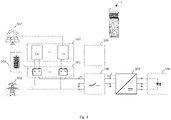
- Fig. 1 illustrates an emergency lighting system 1 according to an embodiment of the present disclosure.
- the emergency lighting system 1 comprises energy storage means 101 and an emergency lighting driver 105.
- the emergency lighting system 1 may further comprise lighting means 106 connectable to the emergency lighting system 1.
- the emergency lighting driver 105 may be an AC/DC converter, for example being able to operate the lighting means either from AC or DC supply.
- the energy storage means 101 may comprise a modular energy storage means 101.
- This may provide a higher degree of reliability (i.e., structural redundancy), and may enable taking advantage of scalability instead of using 12V lead (Pb) acid batteries in series even when not using a PV system.
- the energy storage means 101 may be located remotely from the emergency lighting driver 105; may comprise a rechargeable battery, and may in particular comprise a solar battery.
- This may enable linking up with energy storage means 101 already installed in a building, provide a higher degree of self-sufficiency, as self-produced energy is used, and provide an environmentally friendly EL system powered by solar power.
- Such energy storage means 101 are typically not discharged to SOC values close to 0%, but operated above an SOC threshold ranging between about 10% and 30% in order to maximize a service life of the energy storage means 101.
- SOC threshold ranging between about 10% and 30% in order to maximize a service life of the energy storage means 101.
- a charge below the SOC threshold is typically more than sufficient for emergency lighting.
- the SOC threshold 104 may comprise an SOC of 10%, preferably 20%, and more preferably 30%. The higher the applicable SOC threshold 104, the more capacity may be reserved for emergency response.
- the emergency lighting system 1 is operable under non-emergency (i.e., normal) conditions as well as under emergency conditions, which may comprise a failure of the power grid 103, in particular.
- the energy storage means 101 is operable above the SOC threshold 104.
- the energy storage means 101 may be chargeable by the power grid 103 in response to a price of grid supply below a threshold.
- a price threshold of 0,- € charging may take place in response to a negative price of grid supply, for example.
- charging may occur in response to a low price of grid supply.
- the energy storage means 101 may further be dischargeable to the power grid 103 in response to a peak load signaled by the power grid 103, for example.
- the emergency lighting system 1 may be operable to drive the lighting means 106 (such as LED luminaires, or other loads) off the energy storage means 101, using the charge above the SOC threshold 104.
- the lighting means 106 can as well be operated directly off the power grid 103.
- One main task of the emergency lighting system 1 is therefore to decide whether the loads are operated directly from the power grid 103 or from the connected energy storage means 101. It therefore may comprise a load switch 108 to select the appropriate supply 101, 103.
- the emergency lighting driver 105 is operable to drive the lighting means 106 (depicted on a right portion of Fig. 1 ) off the energy storage means 101, using a charge below the SOC threshold 104 reserved for emergency response.
- the emergency lighting driver 105 may be operable to drive the lighting means 106 for a period in excess of a multiple of a legally required emergency service time in dependence of the SOC of the energy storage means 101.
- the emergency lighting system 1 may further comprise a battery management unit 107 (depicted on a top-left portion of Fig. 1 ) of and connectable to the energy storage means 101.
- the emergency lighting system 1 may be configured to communicate with this battery management unit 107 so as to establish the SOC threshold 104, an SOC and/or a testing status of the energy storage means 101.
- PV and EL system may share its capacity by reserving a fraction thereof for emergency response.
- Such a communication on status and legally required testing may be mandated by a logical and/or spatial separation of the EL system 1 and the battery management 107.
- the battery management 107 may manage the energy storage means 101 and reserve the capacity needed for emergency response, while the EL system 1 may manage the lighting means 106 and perform the required testing and documentation.
- the emergency lighting system 1 may further comprise a control unit 109 for the emergency lighting system 1.
- the control unit 109 may be designed for implementing a method 2 according to a second aspect of the present disclosure or any of its embodiments, which will be explained next.
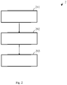
- Fig. 2 illustrates a method 2 of operating an emergency lighting system 1 comprising energy storage means 101 according to an embodiment of the present disclosure.
- the method 2 comprises basic steps of charging 201, operating 202 and driving 203.
- Step 201 involves charging the energy storage means 101 by a photovoltaic system 102 and/or a power grid 103 connectable to the emergency lighting system 1.
- Step 202 involves operating the energy storage means 101 above a state of charge SOC under non-emergency conditions.
- Step 203 involves driving lighting means 106 connectable to the emergency lighting system 1 off the energy storage means 101 in response to emergency conditions, using a charge below the SOC reserved for emergency response.
- the method 2 may be performed by an emergency lighting system 1 according to a first aspect of the present disclosure or any of its embodiments.
Landscapes
- Engineering & Computer Science (AREA)
- Power Engineering (AREA)
- Business, Economics & Management (AREA)
- Emergency Management (AREA)
- Charge And Discharge Circuits For Batteries Or The Like (AREA)
- Circuit Arrangement For Electric Light Sources In General (AREA)
- Supply And Distribution Of Alternating Current (AREA)
Priority Applications (3)
| Application Number | Priority Date | Filing Date | Title |
|---|---|---|---|
| EP20215864.8A EP4016785A1 (fr) | 2020-12-21 | 2020-12-21 | Système d'éclairage de secours à batterie centrale |
| CN202180079706.XA CN116601846A (zh) | 2020-12-21 | 2021-12-15 | 中央电池应急照明系统 |
| PCT/EP2021/085940 WO2022136058A1 (fr) | 2020-12-21 | 2021-12-15 | Système d'éclairage d'urgence à batterie centrale |
Applications Claiming Priority (1)
| Application Number | Priority Date | Filing Date | Title |
|---|---|---|---|
| EP20215864.8A EP4016785A1 (fr) | 2020-12-21 | 2020-12-21 | Système d'éclairage de secours à batterie centrale |
Publications (1)
| Publication Number | Publication Date |
|---|---|
| EP4016785A1 true EP4016785A1 (fr) | 2022-06-22 |
Family
ID=73856046
Family Applications (1)
| Application Number | Title | Priority Date | Filing Date |
|---|---|---|---|
| EP20215864.8A Pending EP4016785A1 (fr) | 2020-12-21 | 2020-12-21 | Système d'éclairage de secours à batterie centrale |
Country Status (3)
| Country | Link |
|---|---|
| EP (1) | EP4016785A1 (fr) |
| CN (1) | CN116601846A (fr) |
| WO (1) | WO2022136058A1 (fr) |
Citations (5)
| Publication number | Priority date | Publication date | Assignee | Title |
|---|---|---|---|---|
| KR20000015790A (ko) * | 1997-03-19 | 2000-03-15 | 넥스텍 파워 시스템즈, 인코포레이티드 | 고효율 조명을 위한 전력 시스템 |
| WO2010057138A2 (fr) * | 2008-11-14 | 2010-05-20 | Inovus Solar, Inc. | Éclairage d'extérieur économe en énergie à alimentation solaire |
| EP2437374A2 (fr) * | 2010-10-01 | 2012-04-04 | Birchcroft Plc. | Système d'éclairage CC |
| US20180054070A1 (en) * | 2016-08-16 | 2018-02-22 | Helion Concepts,Inc. | Hardware/software reconfigurable, intelligent and versatile electrical energy provisioning system for on-grid and off-grid applications |
| CN111404186A (zh) * | 2020-05-11 | 2020-07-10 | 国网湖南省电力有限公司 | 一种配变动态增容智能储能装置及控制方法 |
-
2020
- 2020-12-21 EP EP20215864.8A patent/EP4016785A1/fr active Pending
-
2021
- 2021-12-15 CN CN202180079706.XA patent/CN116601846A/zh active Pending
- 2021-12-15 WO PCT/EP2021/085940 patent/WO2022136058A1/fr not_active Ceased
Patent Citations (5)
| Publication number | Priority date | Publication date | Assignee | Title |
|---|---|---|---|---|
| KR20000015790A (ko) * | 1997-03-19 | 2000-03-15 | 넥스텍 파워 시스템즈, 인코포레이티드 | 고효율 조명을 위한 전력 시스템 |
| WO2010057138A2 (fr) * | 2008-11-14 | 2010-05-20 | Inovus Solar, Inc. | Éclairage d'extérieur économe en énergie à alimentation solaire |
| EP2437374A2 (fr) * | 2010-10-01 | 2012-04-04 | Birchcroft Plc. | Système d'éclairage CC |
| US20180054070A1 (en) * | 2016-08-16 | 2018-02-22 | Helion Concepts,Inc. | Hardware/software reconfigurable, intelligent and versatile electrical energy provisioning system for on-grid and off-grid applications |
| CN111404186A (zh) * | 2020-05-11 | 2020-07-10 | 国网湖南省电力有限公司 | 一种配变动态增容智能储能装置及控制方法 |
Also Published As
| Publication number | Publication date |
|---|---|
| WO2022136058A1 (fr) | 2022-06-30 |
| CN116601846A (zh) | 2023-08-15 |
Similar Documents
| Publication | Publication Date | Title |
|---|---|---|
| US12476474B2 (en) | Charging system for swapping station or energy storage station | |
| US20240396362A1 (en) | Hybrid battery system | |
| US6795322B2 (en) | Power supply with uninterruptible function | |
| US20110304298A1 (en) | Battery charging using multiple chargers | |
| US20160214491A1 (en) | Charging facility and energy management method for charging facility | |
| CN205489759U (zh) | 一种光伏储能空调装置 | |
| JP6800353B2 (ja) | 照明電源システム及び方法 | |
| KR20180090673A (ko) | 하이브리드 에너지 저장 시스템 | |
| KR20200048913A (ko) | 폐배터리 기반의 독립형 가정용 에너지 저장 시스템 | |
| CN210074859U (zh) | 一种具备电网回馈功能的光储充一体化系统 | |
| JPH10336916A (ja) | 非常用電源システム | |
| EP4657698A1 (fr) | Système de micro-réseau | |
| JP2001177995A (ja) | ハイブリッド電源システム | |
| CN111406352B (zh) | 储能系统 | |
| EP4016785A1 (fr) | Système d'éclairage de secours à batterie centrale | |
| EP4118728B1 (fr) | Système d'éclairage d'urgence | |
| CN114123461A (zh) | 移动式电化学储能组站不停电系统及控制方法 | |
| JP2016063716A (ja) | 給電設備及びその運転方法 | |
| CN218735088U (zh) | 多模式充电应急灯电路及照明设备 | |
| KR101215396B1 (ko) | 방전전류제어를 이용한 하이브리드 스마트그리드 무정전전원장치 | |
| KR20210076592A (ko) | 멀티 배터리의 순환 방전을 이용한 전원 공급 시스템 | |
| US12100992B2 (en) | Battery for an emergency lighting unit | |
| CN111095717A (zh) | 储能系统 | |
| US20160276850A1 (en) | Charging Bus | |
| KR101742796B1 (ko) | 직류 고전압 대용량 무접점 스위칭 장치를 이용한 이차 전지 충방전 전원 장치 |
Legal Events
| Date | Code | Title | Description |
|---|---|---|---|
| PUAI | Public reference made under article 153(3) epc to a published international application that has entered the european phase |
Free format text: ORIGINAL CODE: 0009012 |
|
| STAA | Information on the status of an ep patent application or granted ep patent |
Free format text: STATUS: THE APPLICATION HAS BEEN PUBLISHED |
|
| AK | Designated contracting states |
Kind code of ref document: A1 Designated state(s): AL AT BE BG CH CY CZ DE DK EE ES FI FR GB GR HR HU IE IS IT LI LT LU LV MC MK MT NL NO PL PT RO RS SE SI SK SM TR |
|
| STAA | Information on the status of an ep patent application or granted ep patent |
Free format text: STATUS: REQUEST FOR EXAMINATION WAS MADE |
|
| 17P | Request for examination filed |
Effective date: 20221208 |
|
| RBV | Designated contracting states (corrected) |
Designated state(s): AL AT BE BG CH CY CZ DE DK EE ES FI FR GB GR HR HU IE IS IT LI LT LU LV MC MK MT NL NO PL PT RO RS SE SI SK SM TR |
|
| STAA | Information on the status of an ep patent application or granted ep patent |
Free format text: STATUS: EXAMINATION IS IN PROGRESS |
|
| 17Q | First examination report despatched |
Effective date: 20250409 |