EP4016831B1 - Sensorlose steuerung eines motors durch eine variable frequenzsignalinjektion - Google Patents
Sensorlose steuerung eines motors durch eine variable frequenzsignalinjektion Download PDFInfo
- Publication number
- EP4016831B1 EP4016831B1 EP20306592.5A EP20306592A EP4016831B1 EP 4016831 B1 EP4016831 B1 EP 4016831B1 EP 20306592 A EP20306592 A EP 20306592A EP 4016831 B1 EP4016831 B1 EP 4016831B1
- Authority
- EP
- European Patent Office
- Prior art keywords
- current
- high frequency
- frequency signal
- motor
- signal
- Prior art date
- Legal status (The legal status is an assumption and is not a legal conclusion. Google has not performed a legal analysis and makes no representation as to the accuracy of the status listed.)
- Active
Links
Images

Classifications
-
- H—ELECTRICITY
- H02—GENERATION; CONVERSION OR DISTRIBUTION OF ELECTRIC POWER
- H02P—CONTROL OR REGULATION OF ELECTRIC MOTORS, ELECTRIC GENERATORS OR DYNAMO-ELECTRIC CONVERTERS; CONTROLLING TRANSFORMERS, REACTORS OR CHOKE COILS
- H02P6/00—Arrangements for controlling synchronous motors or other dynamo-electric motors using electronic commutation dependent on the rotor position; Electronic commutators therefor
- H02P6/14—Electronic commutators
- H02P6/16—Circuit arrangements for detecting position
- H02P6/18—Circuit arrangements for detecting position without separate position detecting elements
- H02P6/183—Circuit arrangements for detecting position without separate position detecting elements using an injected high frequency signal
-
- H—ELECTRICITY
- H02—GENERATION; CONVERSION OR DISTRIBUTION OF ELECTRIC POWER
- H02P—CONTROL OR REGULATION OF ELECTRIC MOTORS, ELECTRIC GENERATORS OR DYNAMO-ELECTRIC CONVERTERS; CONTROLLING TRANSFORMERS, REACTORS OR CHOKE COILS
- H02P21/00—Arrangements or methods for the control of electric machines by vector control, e.g. by control of field orientation
- H02P21/14—Estimation or adaptation of machine parameters, e.g. flux, current or voltage
-
- H—ELECTRICITY
- H02—GENERATION; CONVERSION OR DISTRIBUTION OF ELECTRIC POWER
- H02P—CONTROL OR REGULATION OF ELECTRIC MOTORS, ELECTRIC GENERATORS OR DYNAMO-ELECTRIC CONVERTERS; CONTROLLING TRANSFORMERS, REACTORS OR CHOKE COILS
- H02P21/00—Arrangements or methods for the control of electric machines by vector control, e.g. by control of field orientation
- H02P21/14—Estimation or adaptation of machine parameters, e.g. flux, current or voltage
- H02P21/18—Estimation of position or speed
-
- H—ELECTRICITY
- H02—GENERATION; CONVERSION OR DISTRIBUTION OF ELECTRIC POWER
- H02P—CONTROL OR REGULATION OF ELECTRIC MOTORS, ELECTRIC GENERATORS OR DYNAMO-ELECTRIC CONVERTERS; CONTROLLING TRANSFORMERS, REACTORS OR CHOKE COILS
- H02P21/00—Arrangements or methods for the control of electric machines by vector control, e.g. by control of field orientation
- H02P21/22—Current control, e.g. using a current control loop
-
- H—ELECTRICITY
- H02—GENERATION; CONVERSION OR DISTRIBUTION OF ELECTRIC POWER
- H02P—CONTROL OR REGULATION OF ELECTRIC MOTORS, ELECTRIC GENERATORS OR DYNAMO-ELECTRIC CONVERTERS; CONTROLLING TRANSFORMERS, REACTORS OR CHOKE COILS
- H02P21/00—Arrangements or methods for the control of electric machines by vector control, e.g. by control of field orientation
- H02P21/24—Vector control not involving the use of rotor position or rotor speed sensors
-
- H—ELECTRICITY
- H02—GENERATION; CONVERSION OR DISTRIBUTION OF ELECTRIC POWER
- H02P—CONTROL OR REGULATION OF ELECTRIC MOTORS, ELECTRIC GENERATORS OR DYNAMO-ELECTRIC CONVERTERS; CONTROLLING TRANSFORMERS, REACTORS OR CHOKE COILS
- H02P25/00—Arrangements or methods for the control of AC motors characterised by the kind of AC motor or by structural details
- H02P25/02—Arrangements or methods for the control of AC motors characterised by the kind of AC motor or by structural details characterised by the kind of motor
- H02P25/022—Synchronous motors
-
- H—ELECTRICITY
- H02—GENERATION; CONVERSION OR DISTRIBUTION OF ELECTRIC POWER
- H02P—CONTROL OR REGULATION OF ELECTRIC MOTORS, ELECTRIC GENERATORS OR DYNAMO-ELECTRIC CONVERTERS; CONTROLLING TRANSFORMERS, REACTORS OR CHOKE COILS
- H02P25/00—Arrangements or methods for the control of AC motors characterised by the kind of AC motor or by structural details
- H02P25/02—Arrangements or methods for the control of AC motors characterised by the kind of AC motor or by structural details characterised by the kind of motor
- H02P25/022—Synchronous motors
- H02P25/024—Synchronous motors controlled by supply frequency
- H02P25/026—Synchronous motors controlled by supply frequency thereby detecting the rotor position
-
- H—ELECTRICITY
- H02—GENERATION; CONVERSION OR DISTRIBUTION OF ELECTRIC POWER
- H02P—CONTROL OR REGULATION OF ELECTRIC MOTORS, ELECTRIC GENERATORS OR DYNAMO-ELECTRIC CONVERTERS; CONTROLLING TRANSFORMERS, REACTORS OR CHOKE COILS
- H02P27/00—Arrangements or methods for the control of AC motors characterised by the kind of supply voltage
- H02P27/04—Arrangements or methods for the control of AC motors characterised by the kind of supply voltage using variable-frequency supply voltage, e.g. inverter or converter supply voltage
- H02P27/06—Arrangements or methods for the control of AC motors characterised by the kind of supply voltage using variable-frequency supply voltage, e.g. inverter or converter supply voltage using DC to AC converters or inverters
- H02P27/08—Arrangements or methods for the control of AC motors characterised by the kind of supply voltage using variable-frequency supply voltage, e.g. inverter or converter supply voltage using DC to AC converters or inverters with pulse width modulation
- H02P27/085—Arrangements or methods for the control of AC motors characterised by the kind of supply voltage using variable-frequency supply voltage, e.g. inverter or converter supply voltage using DC to AC converters or inverters with pulse width modulation wherein the PWM mode is adapted on the running conditions of the motor, e.g. the switching frequency
-
- H—ELECTRICITY
- H02—GENERATION; CONVERSION OR DISTRIBUTION OF ELECTRIC POWER
- H02P—CONTROL OR REGULATION OF ELECTRIC MOTORS, ELECTRIC GENERATORS OR DYNAMO-ELECTRIC CONVERTERS; CONTROLLING TRANSFORMERS, REACTORS OR CHOKE COILS
- H02P2207/00—Indexing scheme relating to controlling arrangements characterised by the type of motor
- H02P2207/05—Synchronous machines, e.g. with permanent magnets or DC excitation
Definitions
- This disclosure relates to a control method for an electric motor.
- This disclosure also relates to a variable speed drive capable of controlling the electric motor.
- This disclosure also relates to an electric drive assembly comprising the variable speed drive and the electric motor.
- Electric motors such as induction motors or Permanent Magnet Synchronous Motors (PMSM) are commonly controlled by a Variable Speed Drive (VSD) using vector control.
- VSD Variable Speed Drive
- FOC Field Oriented Control
- FOC relies on the correct acquisition of the motor's rotor position.
- Rotor position is typically obtained by means of an optical or magnetic transducer (encoder), or extra windings in the rotor (resolver).
- encoder optical or magnetic transducer
- resolver extra windings in the rotor
- HF High Frequency
- EP 3 709 500 A1 states that a method for estimating the amplitude of a periodic component in a measured signal comprises performing a delta-sigma modulation on a received analog signal to obtain a digital signal; applying at least one filter to the digital signal and to a first periodic signal to estimate a first amplitude signal representative of the first periodic signal in the digital signal.
- the method further comprises a control operation of adapting a control law of an external entity based on at least the first amplitude signal; or calculating a monitoring value based on at least the first amplitude signal.
- a control device for an AC rotary machine includes a magnetic-pole-position correction amount calculation device that calculates a magnetic-pole-position correction amount based on a detection-current vector detected when a voltage application device applies a voltage to the AC rotary machine according to a voltage command and on the voltage command, and stores in a storage device the magnetic-pole-position correction amount as it is associated with the detection-current vector.
- a voltage-vector command generation device generates a voltage command for normal operation based on the detection-current vector detected by a current vector detection device and the magnetic-pole-position correction amount associated with the detection-current vector.
- High frequency signal injection has been shown to produce good results compared to other sensorless control strategies, especially at low motor speeds. However, it has also been shown to produce acoustic noise, vibration and additional losses in the motor. Decreasing the amplitude of the high frequency signal may reduce the acoustic noise, but also decreases the Signal-to-Noise Ratio (SNR) which makes it more difficult to extract the information contained in the high frequency current.
- SNR Signal-to-Noise Ratio
- the present invention aims to provide a high frequency signal injection control strategy which does not present the disadvantages mentioned above.
- variable frequency or frequencies of the high frequency signal can spread the spectrum of acoustic noise produced by the motor when the excitation voltage is applied to the motor.
- demodulating the current signal to obtain motor information is adapted to the varying frequency or frequencies of the high frequency signal.
- variable speed drive of an electric motor comprising a processor and a memory, the processor being configured to operate according to any of the above method.
- an electric drive assembly comprising the variable speed drive and an electric motor controlled by said variable speed drive.
- FIG 1 is a schematic diagram of an electric drive assembly 10 according to the present disclosure.
- the electric drive assembly 10 may be used in diverse industrial settings. For example, it may drive a fan of a heating, ventilation and air conditioning (HVAC) system. As another example, it may also be used to drive a water pump of a sewage installation. As yet another example, it may drive a conveyer on an assembly line. Many other industrial applications may be envisaged by the skilled person.
- HVAC heating, ventilation and air conditioning
- the electric drive assembly 10 comprises a variable speed drive 12, or VSD, and an electric motor 14.
- the electric motor 14 is an AC (Alternating Current) motor 14, preferably a synchronous motor, such as a permanent magnet synchronous motor (PMSM), or a synchronous reluctance motor (SynRM).
- a synchronous motor such as a permanent magnet synchronous motor (PMSM), or a synchronous reluctance motor (SynRM).
- the variable speed drive 12 is electrically connected to the electric motor 14.
- the variable speed drive 12 controls the operation of the electric motor 14 according to a control method.
- the variable speed drive 12 enables the electric motor 14 to be operated at a speed desired for the application.
- the variable speed drive 12 also allows controlling the torque output of the electric motor 14 to a load.
- the variable speed drive 12 generally comprises a rectifier module 16, a DC (Direct Current) power bus 18 and an inverter module 20.
- the rectifier module 16 comprises a diode bridge configured to convert a 3-phase AC voltage provided by an electrical grid G to a DC voltage.
- the DC voltage outputted by the rectifier module 12 may be applied to the DC power bus 18.
- the DC power bus 18 comprises two power lines connected together by a bus capacitor C bus configured to stabilize the voltage of the bus 18.
- the output of the DC power bus 18 may be connected to the inverter module 20.
- the inverter module 20 comprises several switching arms each comprising power transistors, for example of the IGBT (Insulated Gate Bipolar Transistor) type.
- the inverter module 20 may be intended to cut off the voltage supplied by the DC power bus 16, to achieve a variable output voltage which can operate the electric motor 14.
- variable speed drive 12 comprises a processor PROC.
- the processor PROC controls the other electrical components of the variable speed drive 12.
- the processor PROC is configured to operate according to the control method.
- Processor PROC may comprise electronic circuits for computation managed by an operating system.
- the variable speed drive 12 also comprises a non-transitory machine-readable or computer readable storage medium, such as, for example, memory or storage unit MEM, whereby the non-transitory machine-readable storage medium is encoded with instructions executable by processor PROC, the machine-readable storage medium comprising instructions to operate processor PROC to perform as per the control method.
- a computer readable storage according to this disclosure may be any electronic, magnetic, optical or other physical storage device that stores executable instructions.
- the computer readable storage may be, for example, Random Access Memory (RAM), an Electrically Erasable Programmable Read Only Memory (EEPROM), a storage drive, and optical disk, and the like.
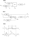
- Figure 2 illustrates a control system used by the variable speed drive 12 to control the operation of the motor 14.
- the control system enables the variable speed 12 drive to operate according to the control method described below.
- the control method comprises, at step 101, determining a control voltage u 0 .
- the control voltage u 0 is that which, when applied to the motor 14, will cause it to operate in the conditions desired for the application.
- the control voltage u 0 may enable the motor 14 to operate at a desired speed.
- determining the control voltage u 0 of the motor 14 at step 101 is achieved through field oriented control, or FOC.
- Figure 3 illustrates in more detail step 101 of determining the control voltage u 0 using FOC.
- determining the control voltage u 0 relies on a reference speed ⁇ ref , a flux reference ⁇ ref and information on the state of the motor 14.
- the speed reference ⁇ ref is that which the motor 14 is desired to operate at for the application.
- the flux reference ⁇ ref may be derived from the speed reference ⁇ ref and motor specifications.
- the information on the state of the motor 14 comprises a flux ⁇ and an actual speed ⁇ produced by the motor 14.
- the information on the state of the motor is derived from measurements taken at the motor 14.
- the control system is a closed loop system. In other words, determining a control voltage u 0 is achieved by receiving feedback on the instantaneous status of the motor 14 during the operation of the motor 14.
- the variable speed drive 12 adjusts the control voltage u 0 based on the feedback received.
- the control method is a sensorless control method. This means that the feedback entirely relies on current measurements provided by current sensors embedded in the variable speed drive 12. There are no external sensors mounted on the motor 14, such as shaft encoders and the like, to provide feedback to the variable speed drive 12 on the status of the motor 14.
- determining the control voltage u 0 of the motor 14 comprises using a speed controller and a flux controller.
- the speed controller at step 1010, derives a torque producing current l q from the reference speed ⁇ ref and the actual speed ⁇ of the motor 14.
- the flux controller at step 1011, derives a magnetizing current l d from the flux reference ⁇ ref and the actual flux ⁇ of the motor 14.
- the speed and the flux controllers may derive the torque producing current and the magnetizing current using proportional integral (PI) control.
- the torque producing current I q and the magnetizing current I d are two orthogonal signals.
- Determining the control voltage u 0 also comprises, at step 1012, using a current controller.
- the current controller converts the two orthogonal signals l q , I d into the control voltage u 0 .
- the current controller may convert the two orthogonal signals l q , I d using the current measurements taken at the motor 14. It should be noted that the control voltage u 0 determined according to FOC also comprises two orthogonal components (not represented here for simplicity).
- Determining the control voltage u 0 further comprises, at step 1013, changing the reference frame of the control voltage u 0 .
- the control voltage u 0 may be expressed in a rotor reference frame or a stator reference frame.
- the control voltage u 0 is initially determined in an estimation of the rotor reference frame, before being converted to the stator reference frame.
- the control voltage u 0 expressed in the stator reference frame defines the voltages to be applied to the stator windings to obtain the desired speed or torque from the motor 14.
- the control method comprises, at step 102, injecting a high frequency signal S 0 into the control voltage u 0 to obtain an excitation voltage u 1 .
- the excitation voltage u 1 is the combination of the control voltage u 0 and the high frequency signal S 0 .
- the high frequency signal S 0 integrates the control voltage u 0 .
- the high frequency signal S 0 could be a signal comprising multiple frequencies, in particular a fundamental frequency and any number of harmonic frequencies.
- the high frequency signal S 0 may be a square wave signal. The use of a square wave signal simplifies the synthetization of the high frequency signal S 0 .
- the high frequency signal S 0 could be a sinusoidal signal or any other shape signal.
- the one or more frequencies of the high frequency signal S 0 vary with time.
- the one or more frequencies of the high frequency signal S 0 vary randomly with time. In other words, the one or more frequencies of the high frequency signal S 0 do not follow a repeating pattern.
- the random variations of the high frequency signal S 0 spreads the spectra of acoustic noise produced in the motor 14 when the excitation voltage u 1 is applied to the motor 14. A reduction in the audible noise produced in the motor 14 may be achieved.
- the one or more frequencies of the high frequency signal S 0 are superior to a frequency bandwidth of the current controller used to determine control voltage u 0 at step 101.
- the high frequency signal S 0 does not interfere with the desired operation of the motor 14.
- the fundamental frequency of the high frequency signal S 0 can vary between 250 Hz and 1 kHz.
- the high frequency signal S 0 is injected in the estimated rotor reference frame.
- the high frequency signal S 0 could be injected in the stator reference frame.
- the high frequency signal S 0 could be injected in either orthogonal components forming the control voltage u 0 .
- the control method comprises, at block 103, converting the excitation voltage u 1 to a pulse width modulated voltage u pwm . Converting the excitation voltage u 1 to a pulse width modulation voltage u pwm uses a pulse width modulation carrier u car . Using the pulse width modulation carrier u car refers to modulating the excitation voltage u 1 with the pulse width modulation carrier u car .
- the frequency of the pulse-width modulated carrier u car is superior to the fundamental frequency of the high frequency signal S 0 .
- the pulse-width modulated carrier u car may have a frequency between 2 and 16 kHz.
- the fundamental frequency of the high frequency signal S 0 is therefore within an interval defined by the frequency bandwidth of the current controller and the frequency of the pulse-width modulated carrier u car .
- the fundamental frequency of the high frequency signal S 0 is close to the frequency of the pulse-width modulated carrier u car , so as not to disturb the desired operation of the motor 14.
- figure 2 shows a single phase control system 22. This is only for simplification.
- the electric motor 14 will be a three-phase motor. In this case, converting the excitation voltage u 1 at step 103 generates a pulse width modulated voltage u pwm for each of the three phases of the motor 14.
- the control method comprises, at step 104, applying the excitation voltage u 1 to the motor 14.
- the excitation voltage u 1 in the form of the pulse-width modulated voltage u pwm is sent to the converter 20 of the variable speed drive 12 to operate the motor 14.
- the motor 14 will react to the excitation voltage u 1 by rotating at a speed ⁇ and producing current y in stator windings.
- the control method comprises, at step 106, measuring the current y induced by the motor 14 during operation. As noted above, current measurements are provided by the variable speed drive 12.
- the current y measured at step 106 comprises a fundamental current y a and a disturbance current y b S 1 .
- the fundamental current y a is that induced by the control voltage u 0 .
- the fundamental current y a would be measured without injecting the high frequency signal S 0 at step 102.
- the fundamental current y a may be fed back to the control step 101 to update the control voltage u 0 .
- the fundamental current y a may be used by the current controller.
- the disturbance current y b S 1 is that induced by the high frequency signal S 0 .
- the disturbance current y b S 1 is the primitive S 1 of the injected high frequency signal S 0 modulated in amplitude by a ripple y b .
- An amplitude of the ripple y b is the amplitude of the motor's response to the high frequency signal So, and contains the information on the state of the motor used at step 101 to determine the control voltage u 0 .
- the amplitude of the ripple y b may be fed back to the control block 101 to update the control voltage u 0 .
- the amplitude of the ripple y b may provide the speed ⁇ and flux ⁇ used by the speed controller and the flux controller.
- the method comprises, at step 107, demodulating the current y measured at step 106.
- Demodulating the current y comprises separating the disturbance current y b S 1 from the fundamental current y a .
- Demodulating the current y also comprises determining the amplitude of the ripple y b of the disturbance current y b S 1 .
- the fundamental current y a and amplitude of the ripple y b can thus be fed back to the control step 101 to update the control voltage u 0 .
- the control system 22 is a closed loop control system 22.
- Block 107 of demodulating the signal is shown in more detail in figure 4 .
- demodulating the current y comprises, at block 1071, applying a first finite impulse response (FIR) filter to the current signal y.
- FIR finite impulse response
- a response of an FIR filter is of finite duration, and does not rely on previous inputs to the filter.
- the duration of the response from the first impulse response filter can therefore be adapted to the one or more frequencies of the high frequency signal S 0 .
- the duration of the response from the first impulse response filter can correspond to the one or more frequencies of the high frequency signal S 0 .
- the finite impulse response filter can thus suitably remove the disturbance current y b S 1 from the current y.
- the fundamental current y a may be extracted from the current y.
- Demodulating the current further comprises, at step 1072, subtracting the fundamental current y a from the current y.
- the disturbance current y b S 1 is separated from the current y.
- the disturbance current y b S 1 may be extracted from the current y.
- Demodulating the current y comprises determining the amplitude of the ripple y b , which carries the information on the state of the motor 14.
- the actual speed ⁇ and flux ⁇ used by the speed controller and the flux controller at step 101 may be determined from the amplitude of the ripple y b .
- Determining the amplitude of the ripple y b comprises calculating, at step 1073, the zero mean primitive S 1 of the high frequency signal S 0 .
- zero-mean primitive S 1 it is to be understood the primitive which is zero in average over each period of the high frequency signal S 0 .
- Determining the amplitude of the ripple y b comprises, at step 1074 multiplying the zero mean primitive S 1 of the high frequency signal S 0 with the disturbance current y b S 1 . It should be noted that multiplying the zero mean primitive S 1 of the high frequency signal S 0 with the disturbance current y b S 1 also comprises taking the transpose of the zero mean primitive S 1 of the high frequency signal S 0 . The ripple y b may thus be extracted from the disturbance current y b S 1 .
- Determining the amplitude of the ripple y b comprises, at step 1075, applying a second finite impulse response to the ripple y b .
- step 1075 comprises taking a sliding average of the disturbance current y b S 1 multiplied by the zero mean primitive S 1 .
- the sliding average corresponds to the amplitude of the ripple y b .
- the finite impulse response filter is particularly adapted to the varying frequency or frequencies of the disturbance current y b S 1 .
- Figure 5 illustrates an example of a high frequency signal S 0 which may be injected into the control voltage u 0 at step 102 and the disturbance current y b S 1 induced as a result of the injected high frequency signal S 0 .
- the high frequency signal S 0 is a square wave signal.
- the zero-mean primitive S 1 of the high frequency signal S 0 may be easily calculated when demodulating the disturbance current y b S 1 at step 1073.
- the disturbance current y b S 1 is a triangular signal, primitive S 1 of the high frequency signal S 0 modulated in amplitude by the ripple y b .
- the ripple y b may be extracted using the primitive S 1 of the injected signal S 0 as discussed above.
- the frequency of the disturbance current y b S 1 is high for a first duration T1, and low for a second duration T2.
- the duration of the response of the first and second finite impulse response filters applied at steps 1071 and 1075 may be adapted to the first duration T1, and then be adapted to the second duration T2.
- current demodulation is suited to the varying frequency or frequencies of the current y induced by the high frequency signal S 0 .
Landscapes
- Engineering & Computer Science (AREA)
- Power Engineering (AREA)
- Control Of Ac Motors In General (AREA)
- Control Of Motors That Do Not Use Commutators (AREA)
Claims (13)
- Verfahren zur sensorlosen Steuerung eines Elektromotors (14), der in einem Antrieb mit variabler Geschwindigkeit (12) implementiert ist, wobei das Verfahren Folgendes umfasst:- Bestimmen einer Steuerspannung (u0), die an den Motor (14) angelegt wird;- Einspeisen eines Hochfrequenzsignals (S0) in die Steuerspannung (u0), um eine Erregerspannung (u1) zu ermitteln;- Anlegen der Erregerspannung (u1) an den Motor (14);- Messen eines Stroms (y), der in dem Motor durch die Erregerspannung (u1) induziert wird, wobei der Strom (y) einen Grundstrom (ya), der durch die Steuerspannung (u0) induziert wird, und einen Störstrom (ybS1), der durch das Hochfrequenzsignal (S0) induziert wird, umfasst;- Demodulieren des aktuellen Signals (y),- Subtrahieren des Grundstroms (ya) vom Stromsignal (y), um den Störstrom (ybS1) zu extrahieren;- Bestimmen einer Amplitude einer Welligkeit (yb) des Störstroms (ybS1), wobei die Amplitude der Welligkeit (yb) vom Zustand des Motors abhängt,gekennzeichnet dadurch, dass die eine oder mehrere Frequenzen des Hochfrequenzsignals (S0) mit der Zeit variiert werden, und das Demodulieren des Stromsignals (y) umfasst:∘ Anwenden eines ersten Filters mit endlicher Impulsantwort auf das Stromsignal (y), um den Grundstrom (ya) zu extrahieren, wobei eine Dauer einer Antwort des ersten Filters mit endlicher Impulsantwort entsprechend der einen oder mehreren Frequenzen des Hochfrequenzsignals (S0) variiert.
- Verfahren nach Anspruch 1, wobei die Bestimmung der Amplitude der Welligkeit (yb) die Berechnung eines Null-Mittelwert-Primitivs (S1) des Hochfrequenzsignals (S0) und die Multiplikation des Störstroms (ybS1) mit dem Null-Mittelwert-Primitiv (S1) umfasst.
- Verfahren nach Anspruch 2, wobei die Bestimmung der Amplitude der Welligkeit (yb) ferner die Anwendung eines zweiten Filters mit endlicher Impulsantwort umfasst, wobei eine Dauer einer Antwort des zweiten Filters mit endlicher Impulsantwort entsprechend der einen oder mehreren Frequenzen des Hochfrequenzsignals (S0) variiert.
- Verfahren nach einem der Ansprüche 1 bis 3, wobei die eine oder mehrere Frequenzen des Hochfrequenzsignals (S0) mit der Zeit zufällig variieren.
- Verfahren nach einem der Ansprüche 1 bis 4, wobei das Hochfrequenzsignal (S0) ein sinusförmiges Signal ist.
- Verfahren nach einem der Ansprüche 1 bis 4, wobei das Hochfrequenzsignal (S0) ein Rechtecksignal ist.
- Verfahren nach einem der Ansprüche 1 bis 6, wobei das Bestimmen der Steuerspannung (u0) die Verwendung einer Stromsteuerung umfasst, das Anlegen der Erregerspannung (u1) an den Motor das Umwandeln der Erregerspannung (u1) in eine Pulsweitenmodulationsspannung (uPWM) unter Verwendung eines Pulsweitenmodulationsträgers (ucar) umfasst, und eine Grundfrequenz des Hochfrequenzsignals (S0) innerhalb eines Intervalls liegt, das durch eine Frequenzbandbreite der Stromsteuerung und eine Frequenz des Pulsweitenmodulationsträgers (ucar) definiert ist.
- Verfahren nach einem der Ansprüche 7, wobei die Grundfrequenz des Hochfrequenzsignals (S0) zwischen 250 Hz und 1 kHz variiert.
- Verfahren nach einem der Ansprüche 1 bis 8, wobei die Steuerspannung (u0) in einem geschätzten Rotor-Bezugsrahmen des Motors bestimmt wird und das Hochfrequenzsignal (S0) in den geschätzten Rotor-Bezugsrahmen eingespeist wird.
- Verfahren nach einem der Ansprüche 1 bis 9, umfassend das Bilden einer Rückkopplungsschleife durch Aktualisieren der Steuerspannung (u0) mit der Amplitude der Welligkeit (yb) und dem Grundstrom (ya).
- Antrieb (12) eines Elektromotors (14) mit variabler Geschwindigkeit, umfassend einen Prozessor (PROC) und einen Speicher (MEM), wobei der Prozessor (PROC) so konfiguriert ist, dass er nach einem der vorstehenden Ansprüche arbeitet.
- Elektrische Antriebsbaugruppe (10), umfassend den drehzahlvariablen Antrieb (12) nach Anspruch 11 und einen Elektromotor (14), der von dem drehzahlvariablen Antrieb (12) gesteuert wird.
- Computerlesbares Speichermedium, umfassend Anweisungen, die, wenn sie von einem Prozessor ausgeführt werden, den Prozessor veranlassen, das Verfahren nach einem der Ansprüche 1 bis 10 auszuführen.
Priority Applications (4)
| Application Number | Priority Date | Filing Date | Title |
|---|---|---|---|
| ES20306592T ES2982473T3 (es) | 2020-12-17 | 2020-12-17 | Control de pérdida de sensor de un motor mediante inyección de señal de frecuencia variable |
| EP20306592.5A EP4016831B1 (de) | 2020-12-17 | 2020-12-17 | Sensorlose steuerung eines motors durch eine variable frequenzsignalinjektion |
| US17/543,835 US11626821B2 (en) | 2020-12-17 | 2021-12-07 | Sensorless control of a motor by variable frequency signal injection |
| CN202111511875.4A CN114649984A (zh) | 2020-12-17 | 2021-12-07 | 通过可变频率信号注入对马达的无传感器控制 |
Applications Claiming Priority (1)
| Application Number | Priority Date | Filing Date | Title |
|---|---|---|---|
| EP20306592.5A EP4016831B1 (de) | 2020-12-17 | 2020-12-17 | Sensorlose steuerung eines motors durch eine variable frequenzsignalinjektion |
Publications (2)
| Publication Number | Publication Date |
|---|---|
| EP4016831A1 EP4016831A1 (de) | 2022-06-22 |
| EP4016831B1 true EP4016831B1 (de) | 2024-05-08 |
Family
ID=74141320
Family Applications (1)
| Application Number | Title | Priority Date | Filing Date |
|---|---|---|---|
| EP20306592.5A Active EP4016831B1 (de) | 2020-12-17 | 2020-12-17 | Sensorlose steuerung eines motors durch eine variable frequenzsignalinjektion |
Country Status (4)
| Country | Link |
|---|---|
| US (1) | US11626821B2 (de) |
| EP (1) | EP4016831B1 (de) |
| CN (1) | CN114649984A (de) |
| ES (1) | ES2982473T3 (de) |
Families Citing this family (2)
| Publication number | Priority date | Publication date | Assignee | Title |
|---|---|---|---|---|
| US12542502B2 (en) | 2024-02-02 | 2026-02-03 | Stmicroelectronics International N.V. | System and method for indirectly measuring an angular position and/or rotational speed of a wound-rotor motor |
| EP4712334A1 (de) | 2024-09-13 | 2026-03-18 | Schneider Toshiba Inverter Europe SAS | Verfahren zur bestimmung des betriebszustandes einer elektrischen maschine zur sensorlosen steuerung der elektrischen maschine mit signaleinspeisung |
Family Cites Families (3)
| Publication number | Priority date | Publication date | Assignee | Title |
|---|---|---|---|---|
| US9093940B2 (en) * | 2013-02-14 | 2015-07-28 | Deere & Company | Methods of determining initial position of a rotor and systems thereof |
| WO2016038992A1 (ja) * | 2014-09-12 | 2016-03-17 | 三菱電機株式会社 | 交流回転機の制御装置及び磁極位置補正量演算方法 |
| EP3709500B1 (de) * | 2019-03-12 | 2024-11-06 | Schneider Toshiba Inverter Europe SAS | Schätzung der amplitude einer periodischen komponente in einem gemessenen signal durch einen delta-sigma-modulator |
-
2020
- 2020-12-17 ES ES20306592T patent/ES2982473T3/es active Active
- 2020-12-17 EP EP20306592.5A patent/EP4016831B1/de active Active
-
2021
- 2021-12-07 US US17/543,835 patent/US11626821B2/en active Active
- 2021-12-07 CN CN202111511875.4A patent/CN114649984A/zh active Pending
Also Published As
| Publication number | Publication date |
|---|---|
| ES2982473T3 (es) | 2024-10-16 |
| US11626821B2 (en) | 2023-04-11 |
| US20220200493A1 (en) | 2022-06-23 |
| CN114649984A (zh) | 2022-06-21 |
| EP4016831A1 (de) | 2022-06-22 |
Similar Documents
| Publication | Publication Date | Title |
|---|---|---|
| Piippo et al. | Signal injection in sensorless PMSM drives equipped with inverter output filter | |
| US6501243B1 (en) | Synchronous motor-control apparatus and vehicle using the control apparatus | |
| US9124209B2 (en) | Method and apparatus for controlling power converter with inverter output filter | |
| JP3802894B2 (ja) | Acマシンのためのセンサーレス位置制御アルゴリズム | |
| US8624532B2 (en) | System and method for synchronizing sinusoidal drive to permanent magnet motor without distorting drive voltage | |
| US9294019B2 (en) | Method and apparatus for controlling power converter with inverter output filter | |
| Niasar et al. | A novel position sensorless control of a four-switch, brushless DC motor drive without phase shifter | |
| EP2709267A1 (de) | Antriebssystem für elektrischen synchronmotor | |
| WO2009024835A1 (en) | Motor controller for determining a position of a rotor of an ac motor, ac motor system, and method of determining a position of a rotor of an ac motor | |
| US11626821B2 (en) | Sensorless control of a motor by variable frequency signal injection | |
| KR101485989B1 (ko) | 모터 제어 장치 | |
| Park et al. | Sensorless control of brushless DC motors with torque constant estimation for home appliances | |
| Kano et al. | Sensorless control of interior permanent magnet synchronous motor: An overview and design study | |
| JP4542797B2 (ja) | 同期機の制御装置 | |
| JP2019146360A (ja) | インバータ制御装置 | |
| KR100845110B1 (ko) | 센서리스 인버터의 관성 모멘트 추정방법 | |
| JP6726839B2 (ja) | インバータ制御装置 | |
| JP2004282838A (ja) | インバータ駆動誘導電動機の制動方法 | |
| JP7045962B2 (ja) | 交流電動機の制御装置及びその制御方法 | |
| KR100459470B1 (ko) | 유도전동기에서 고주파 주입을이용한 속도 센서리스 벡터 제어기 | |
| Morita et al. | Sensorless Control Based on Extended-EMF Using Current Oversampling for PMSM | |
| Afjei et al. | Analysis of torque ripple reduction methods in switched reluctance motor | |
| JP4720565B2 (ja) | 回転速度検出装置 | |
| JP2007282367A (ja) | モータ駆動制御装置 | |
| KR100356516B1 (ko) | 유도전동기의 속도제어장치 |
Legal Events
| Date | Code | Title | Description |
|---|---|---|---|
| PUAI | Public reference made under article 153(3) epc to a published international application that has entered the european phase |
Free format text: ORIGINAL CODE: 0009012 |
|
| STAA | Information on the status of an ep patent application or granted ep patent |
Free format text: STATUS: THE APPLICATION HAS BEEN PUBLISHED |
|
| AK | Designated contracting states |
Kind code of ref document: A1 Designated state(s): AL AT BE BG CH CY CZ DE DK EE ES FI FR GB GR HR HU IE IS IT LI LT LU LV MC MK MT NL NO PL PT RO RS SE SI SK SM TR |
|
| STAA | Information on the status of an ep patent application or granted ep patent |
Free format text: STATUS: REQUEST FOR EXAMINATION WAS MADE |
|
| 17P | Request for examination filed |
Effective date: 20221209 |
|
| RBV | Designated contracting states (corrected) |
Designated state(s): AL AT BE BG CH CY CZ DE DK EE ES FI FR GB GR HR HU IE IS IT LI LT LU LV MC MK MT NL NO PL PT RO RS SE SI SK SM TR |
|
| GRAP | Despatch of communication of intention to grant a patent |
Free format text: ORIGINAL CODE: EPIDOSNIGR1 |
|
| STAA | Information on the status of an ep patent application or granted ep patent |
Free format text: STATUS: GRANT OF PATENT IS INTENDED |
|
| RIC1 | Information provided on ipc code assigned before grant |
Ipc: H02P 21/18 20160101ALI20231128BHEP Ipc: H02P 6/18 20160101AFI20231128BHEP |
|
| INTG | Intention to grant announced |
Effective date: 20231218 |
|
| GRAS | Grant fee paid |
Free format text: ORIGINAL CODE: EPIDOSNIGR3 |
|
| GRAA | (expected) grant |
Free format text: ORIGINAL CODE: 0009210 |
|
| STAA | Information on the status of an ep patent application or granted ep patent |
Free format text: STATUS: THE PATENT HAS BEEN GRANTED |
|
| AK | Designated contracting states |
Kind code of ref document: B1 Designated state(s): AL AT BE BG CH CY CZ DE DK EE ES FI FR GB GR HR HU IE IS IT LI LT LU LV MC MK MT NL NO PL PT RO RS SE SI SK SM TR |
|
| REG | Reference to a national code |
Ref country code: GB Ref legal event code: FG4D |
|
| REG | Reference to a national code |
Ref country code: CH Ref legal event code: EP |
|
| REG | Reference to a national code |
Ref country code: DE Ref legal event code: R096 Ref document number: 602020030559 Country of ref document: DE |
|
| REG | Reference to a national code |
Ref country code: IE Ref legal event code: FG4D |
|
| REG | Reference to a national code |
Ref country code: LT Ref legal event code: MG9D |
|
| REG | Reference to a national code |
Ref country code: NL Ref legal event code: MP Effective date: 20240508 |
|
| PG25 | Lapsed in a contracting state [announced via postgrant information from national office to epo] |
Ref country code: IS Free format text: LAPSE BECAUSE OF FAILURE TO SUBMIT A TRANSLATION OF THE DESCRIPTION OR TO PAY THE FEE WITHIN THE PRESCRIBED TIME-LIMIT Effective date: 20240908 |
|
| PG25 | Lapsed in a contracting state [announced via postgrant information from national office to epo] |
Ref country code: BG Free format text: LAPSE BECAUSE OF FAILURE TO SUBMIT A TRANSLATION OF THE DESCRIPTION OR TO PAY THE FEE WITHIN THE PRESCRIBED TIME-LIMIT Effective date: 20240508 |
|
| PG25 | Lapsed in a contracting state [announced via postgrant information from national office to epo] |
Ref country code: HR Free format text: LAPSE BECAUSE OF FAILURE TO SUBMIT A TRANSLATION OF THE DESCRIPTION OR TO PAY THE FEE WITHIN THE PRESCRIBED TIME-LIMIT Effective date: 20240508 Ref country code: FI Free format text: LAPSE BECAUSE OF FAILURE TO SUBMIT A TRANSLATION OF THE DESCRIPTION OR TO PAY THE FEE WITHIN THE PRESCRIBED TIME-LIMIT Effective date: 20240508 |
|
| PG25 | Lapsed in a contracting state [announced via postgrant information from national office to epo] |
Ref country code: GR Free format text: LAPSE BECAUSE OF FAILURE TO SUBMIT A TRANSLATION OF THE DESCRIPTION OR TO PAY THE FEE WITHIN THE PRESCRIBED TIME-LIMIT Effective date: 20240809 |
|
| PG25 | Lapsed in a contracting state [announced via postgrant information from national office to epo] |
Ref country code: PT Free format text: LAPSE BECAUSE OF FAILURE TO SUBMIT A TRANSLATION OF THE DESCRIPTION OR TO PAY THE FEE WITHIN THE PRESCRIBED TIME-LIMIT Effective date: 20240909 |
|
| REG | Reference to a national code |
Ref country code: AT Ref legal event code: MK05 Ref document number: 1685841 Country of ref document: AT Kind code of ref document: T Effective date: 20240508 |
|
| REG | Reference to a national code |
Ref country code: ES Ref legal event code: FG2A Ref document number: 2982473 Country of ref document: ES Kind code of ref document: T3 Effective date: 20241016 |
|
| PG25 | Lapsed in a contracting state [announced via postgrant information from national office to epo] |
Ref country code: NL Free format text: LAPSE BECAUSE OF FAILURE TO SUBMIT A TRANSLATION OF THE DESCRIPTION OR TO PAY THE FEE WITHIN THE PRESCRIBED TIME-LIMIT Effective date: 20240508 |
|
| PG25 | Lapsed in a contracting state [announced via postgrant information from national office to epo] |
Ref country code: AT Free format text: LAPSE BECAUSE OF FAILURE TO SUBMIT A TRANSLATION OF THE DESCRIPTION OR TO PAY THE FEE WITHIN THE PRESCRIBED TIME-LIMIT Effective date: 20240508 |
|
| PG25 | Lapsed in a contracting state [announced via postgrant information from national office to epo] |
Ref country code: PL Free format text: LAPSE BECAUSE OF FAILURE TO SUBMIT A TRANSLATION OF THE DESCRIPTION OR TO PAY THE FEE WITHIN THE PRESCRIBED TIME-LIMIT Effective date: 20240508 |
|
| PG25 | Lapsed in a contracting state [announced via postgrant information from national office to epo] |
Ref country code: LV Free format text: LAPSE BECAUSE OF FAILURE TO SUBMIT A TRANSLATION OF THE DESCRIPTION OR TO PAY THE FEE WITHIN THE PRESCRIBED TIME-LIMIT Effective date: 20240508 |
|
| PG25 | Lapsed in a contracting state [announced via postgrant information from national office to epo] |
Ref country code: PT Free format text: LAPSE BECAUSE OF FAILURE TO SUBMIT A TRANSLATION OF THE DESCRIPTION OR TO PAY THE FEE WITHIN THE PRESCRIBED TIME-LIMIT Effective date: 20240909 Ref country code: PL Free format text: LAPSE BECAUSE OF FAILURE TO SUBMIT A TRANSLATION OF THE DESCRIPTION OR TO PAY THE FEE WITHIN THE PRESCRIBED TIME-LIMIT Effective date: 20240508 Ref country code: NO Free format text: LAPSE BECAUSE OF FAILURE TO SUBMIT A TRANSLATION OF THE DESCRIPTION OR TO PAY THE FEE WITHIN THE PRESCRIBED TIME-LIMIT Effective date: 20240808 Ref country code: NL Free format text: LAPSE BECAUSE OF FAILURE TO SUBMIT A TRANSLATION OF THE DESCRIPTION OR TO PAY THE FEE WITHIN THE PRESCRIBED TIME-LIMIT Effective date: 20240508 Ref country code: LV Free format text: LAPSE BECAUSE OF FAILURE TO SUBMIT A TRANSLATION OF THE DESCRIPTION OR TO PAY THE FEE WITHIN THE PRESCRIBED TIME-LIMIT Effective date: 20240508 Ref country code: IS Free format text: LAPSE BECAUSE OF FAILURE TO SUBMIT A TRANSLATION OF THE DESCRIPTION OR TO PAY THE FEE WITHIN THE PRESCRIBED TIME-LIMIT Effective date: 20240908 Ref country code: HR Free format text: LAPSE BECAUSE OF FAILURE TO SUBMIT A TRANSLATION OF THE DESCRIPTION OR TO PAY THE FEE WITHIN THE PRESCRIBED TIME-LIMIT Effective date: 20240508 Ref country code: GR Free format text: LAPSE BECAUSE OF FAILURE TO SUBMIT A TRANSLATION OF THE DESCRIPTION OR TO PAY THE FEE WITHIN THE PRESCRIBED TIME-LIMIT Effective date: 20240809 Ref country code: FI Free format text: LAPSE BECAUSE OF FAILURE TO SUBMIT A TRANSLATION OF THE DESCRIPTION OR TO PAY THE FEE WITHIN THE PRESCRIBED TIME-LIMIT Effective date: 20240508 Ref country code: BG Free format text: LAPSE BECAUSE OF FAILURE TO SUBMIT A TRANSLATION OF THE DESCRIPTION OR TO PAY THE FEE WITHIN THE PRESCRIBED TIME-LIMIT Effective date: 20240508 Ref country code: AT Free format text: LAPSE BECAUSE OF FAILURE TO SUBMIT A TRANSLATION OF THE DESCRIPTION OR TO PAY THE FEE WITHIN THE PRESCRIBED TIME-LIMIT Effective date: 20240508 Ref country code: RS Free format text: LAPSE BECAUSE OF FAILURE TO SUBMIT A TRANSLATION OF THE DESCRIPTION OR TO PAY THE FEE WITHIN THE PRESCRIBED TIME-LIMIT Effective date: 20240808 |
|
| PG25 | Lapsed in a contracting state [announced via postgrant information from national office to epo] |
Ref country code: DK Free format text: LAPSE BECAUSE OF FAILURE TO SUBMIT A TRANSLATION OF THE DESCRIPTION OR TO PAY THE FEE WITHIN THE PRESCRIBED TIME-LIMIT Effective date: 20240508 |
|
| PG25 | Lapsed in a contracting state [announced via postgrant information from national office to epo] |
Ref country code: EE Free format text: LAPSE BECAUSE OF FAILURE TO SUBMIT A TRANSLATION OF THE DESCRIPTION OR TO PAY THE FEE WITHIN THE PRESCRIBED TIME-LIMIT Effective date: 20240508 |
|
| PG25 | Lapsed in a contracting state [announced via postgrant information from national office to epo] |
Ref country code: CZ Free format text: LAPSE BECAUSE OF FAILURE TO SUBMIT A TRANSLATION OF THE DESCRIPTION OR TO PAY THE FEE WITHIN THE PRESCRIBED TIME-LIMIT Effective date: 20240508 |
|
| PG25 | Lapsed in a contracting state [announced via postgrant information from national office to epo] |
Ref country code: SK Free format text: LAPSE BECAUSE OF FAILURE TO SUBMIT A TRANSLATION OF THE DESCRIPTION OR TO PAY THE FEE WITHIN THE PRESCRIBED TIME-LIMIT Effective date: 20240508 Ref country code: RO Free format text: LAPSE BECAUSE OF FAILURE TO SUBMIT A TRANSLATION OF THE DESCRIPTION OR TO PAY THE FEE WITHIN THE PRESCRIBED TIME-LIMIT Effective date: 20240508 |
|
| PG25 | Lapsed in a contracting state [announced via postgrant information from national office to epo] |
Ref country code: SM Free format text: LAPSE BECAUSE OF FAILURE TO SUBMIT A TRANSLATION OF THE DESCRIPTION OR TO PAY THE FEE WITHIN THE PRESCRIBED TIME-LIMIT Effective date: 20240508 |
|
| PGFP | Annual fee paid to national office [announced via postgrant information from national office to epo] |
Ref country code: IT Payment date: 20241220 Year of fee payment: 5 |
|
| PG25 | Lapsed in a contracting state [announced via postgrant information from national office to epo] |
Ref country code: SM Free format text: LAPSE BECAUSE OF FAILURE TO SUBMIT A TRANSLATION OF THE DESCRIPTION OR TO PAY THE FEE WITHIN THE PRESCRIBED TIME-LIMIT Effective date: 20240508 Ref country code: SK Free format text: LAPSE BECAUSE OF FAILURE TO SUBMIT A TRANSLATION OF THE DESCRIPTION OR TO PAY THE FEE WITHIN THE PRESCRIBED TIME-LIMIT Effective date: 20240508 Ref country code: RO Free format text: LAPSE BECAUSE OF FAILURE TO SUBMIT A TRANSLATION OF THE DESCRIPTION OR TO PAY THE FEE WITHIN THE PRESCRIBED TIME-LIMIT Effective date: 20240508 Ref country code: EE Free format text: LAPSE BECAUSE OF FAILURE TO SUBMIT A TRANSLATION OF THE DESCRIPTION OR TO PAY THE FEE WITHIN THE PRESCRIBED TIME-LIMIT Effective date: 20240508 Ref country code: DK Free format text: LAPSE BECAUSE OF FAILURE TO SUBMIT A TRANSLATION OF THE DESCRIPTION OR TO PAY THE FEE WITHIN THE PRESCRIBED TIME-LIMIT Effective date: 20240508 Ref country code: CZ Free format text: LAPSE BECAUSE OF FAILURE TO SUBMIT A TRANSLATION OF THE DESCRIPTION OR TO PAY THE FEE WITHIN THE PRESCRIBED TIME-LIMIT Effective date: 20240508 |
|
| REG | Reference to a national code |
Ref country code: DE Ref legal event code: R097 Ref document number: 602020030559 Country of ref document: DE |
|
| PLBE | No opposition filed within time limit |
Free format text: ORIGINAL CODE: 0009261 |
|
| STAA | Information on the status of an ep patent application or granted ep patent |
Free format text: STATUS: NO OPPOSITION FILED WITHIN TIME LIMIT |
|
| 26N | No opposition filed |
Effective date: 20250211 |
|
| PGFP | Annual fee paid to national office [announced via postgrant information from national office to epo] |
Ref country code: ES Payment date: 20250114 Year of fee payment: 5 |
|
| PG25 | Lapsed in a contracting state [announced via postgrant information from national office to epo] |
Ref country code: SI Free format text: LAPSE BECAUSE OF FAILURE TO SUBMIT A TRANSLATION OF THE DESCRIPTION OR TO PAY THE FEE WITHIN THE PRESCRIBED TIME-LIMIT Effective date: 20240508 |
|
| PG25 | Lapsed in a contracting state [announced via postgrant information from national office to epo] |
Ref country code: MC Free format text: LAPSE BECAUSE OF FAILURE TO SUBMIT A TRANSLATION OF THE DESCRIPTION OR TO PAY THE FEE WITHIN THE PRESCRIBED TIME-LIMIT Effective date: 20240508 |
|
| REG | Reference to a national code |
Ref country code: CH Ref legal event code: PL |
|
| PG25 | Lapsed in a contracting state [announced via postgrant information from national office to epo] |
Ref country code: LU Free format text: LAPSE BECAUSE OF NON-PAYMENT OF DUE FEES Effective date: 20241217 |
|
| PG25 | Lapsed in a contracting state [announced via postgrant information from national office to epo] |
Ref country code: SE Free format text: LAPSE BECAUSE OF FAILURE TO SUBMIT A TRANSLATION OF THE DESCRIPTION OR TO PAY THE FEE WITHIN THE PRESCRIBED TIME-LIMIT Effective date: 20240508 |
|
| REG | Reference to a national code |
Ref country code: BE Ref legal event code: MM Effective date: 20241231 |
|
| PG25 | Lapsed in a contracting state [announced via postgrant information from national office to epo] |
Ref country code: BE Free format text: LAPSE BECAUSE OF NON-PAYMENT OF DUE FEES Effective date: 20241231 |
|
| PG25 | Lapsed in a contracting state [announced via postgrant information from national office to epo] |
Ref country code: CH Free format text: LAPSE BECAUSE OF NON-PAYMENT OF DUE FEES Effective date: 20241231 |
|
| PG25 | Lapsed in a contracting state [announced via postgrant information from national office to epo] |
Ref country code: IE Free format text: LAPSE BECAUSE OF NON-PAYMENT OF DUE FEES Effective date: 20241217 |
|
| PGFP | Annual fee paid to national office [announced via postgrant information from national office to epo] |
Ref country code: GB Payment date: 20251223 Year of fee payment: 6 |
|
| PGFP | Annual fee paid to national office [announced via postgrant information from national office to epo] |
Ref country code: FR Payment date: 20251223 Year of fee payment: 6 |
|
| PGFP | Annual fee paid to national office [announced via postgrant information from national office to epo] |
Ref country code: DE Payment date: 20251229 Year of fee payment: 6 |