EP4016903B1 - Informationsverarbeitungsverfahren, vorrichtung und computerlesbares speichermedium - Google Patents
Informationsverarbeitungsverfahren, vorrichtung und computerlesbares speichermedium Download PDFInfo
- Publication number
- EP4016903B1 EP4016903B1 EP20852242.5A EP20852242A EP4016903B1 EP 4016903 B1 EP4016903 B1 EP 4016903B1 EP 20852242 A EP20852242 A EP 20852242A EP 4016903 B1 EP4016903 B1 EP 4016903B1
- Authority
- EP
- European Patent Office
- Prior art keywords
- pucch
- transmitting
- uci
- spreading factor
- preset condition
- Prior art date
- Legal status (The legal status is an assumption and is not a legal conclusion. Google has not performed a legal analysis and makes no representation as to the accuracy of the status listed.)
- Active
Links
Images



Classifications
-
- H—ELECTRICITY
- H04—ELECTRIC COMMUNICATION TECHNIQUE
- H04L—TRANSMISSION OF DIGITAL INFORMATION, e.g. TELEGRAPHIC COMMUNICATION
- H04L5/00—Arrangements affording multiple use of the transmission path
- H04L5/003—Arrangements for allocating sub-channels of the transmission path
- H04L5/0053—Allocation of signalling, i.e. of overhead other than pilot signals
-
- H—ELECTRICITY
- H04—ELECTRIC COMMUNICATION TECHNIQUE
- H04L—TRANSMISSION OF DIGITAL INFORMATION, e.g. TELEGRAPHIC COMMUNICATION
- H04L1/00—Arrangements for detecting or preventing errors in the information received
- H04L1/0001—Systems modifying transmission characteristics according to link quality, e.g. power backoff
- H04L1/0023—Systems modifying transmission characteristics according to link quality, e.g. power backoff characterised by the signalling
-
- H—ELECTRICITY
- H04—ELECTRIC COMMUNICATION TECHNIQUE
- H04L—TRANSMISSION OF DIGITAL INFORMATION, e.g. TELEGRAPHIC COMMUNICATION
- H04L5/00—Arrangements affording multiple use of the transmission path
- H04L5/0001—Arrangements for dividing the transmission path
- H04L5/0003—Two-dimensional division
- H04L5/0005—Time-frequency
- H04L5/0007—Time-frequency the frequencies being orthogonal, e.g. OFDM(A) or DMT
-
- H—ELECTRICITY
- H04—ELECTRIC COMMUNICATION TECHNIQUE
- H04L—TRANSMISSION OF DIGITAL INFORMATION, e.g. TELEGRAPHIC COMMUNICATION
- H04L5/00—Arrangements affording multiple use of the transmission path
- H04L5/003—Arrangements for allocating sub-channels of the transmission path
- H04L5/0032—Distributed allocation, i.e. involving a plurality of allocating devices, each making partial allocation
- H04L5/0035—Resource allocation in a cooperative multipoint environment
-
- H—ELECTRICITY
- H04—ELECTRIC COMMUNICATION TECHNIQUE
- H04L—TRANSMISSION OF DIGITAL INFORMATION, e.g. TELEGRAPHIC COMMUNICATION
- H04L5/00—Arrangements affording multiple use of the transmission path
- H04L5/0091—Signalling for the administration of the divided path, e.g. signalling of configuration information
- H04L5/0094—Indication of how sub-channels of the path are allocated
-
- H—ELECTRICITY
- H04—ELECTRIC COMMUNICATION TECHNIQUE
- H04W—WIRELESS COMMUNICATION NETWORKS
- H04W72/00—Local resource management
- H04W72/04—Wireless resource allocation
- H04W72/044—Wireless resource allocation based on the type of the allocated resource
- H04W72/0446—Resources in time domain, e.g. slots or frames
-
- H—ELECTRICITY
- H04—ELECTRIC COMMUNICATION TECHNIQUE
- H04W—WIRELESS COMMUNICATION NETWORKS
- H04W72/00—Local resource management
- H04W72/04—Wireless resource allocation
- H04W72/044—Wireless resource allocation based on the type of the allocated resource
- H04W72/0453—Resources in frequency domain, e.g. a carrier in FDMA
-
- H—ELECTRICITY
- H04—ELECTRIC COMMUNICATION TECHNIQUE
- H04W—WIRELESS COMMUNICATION NETWORKS
- H04W72/00—Local resource management
- H04W72/04—Wireless resource allocation
- H04W72/044—Wireless resource allocation based on the type of the allocated resource
- H04W72/0457—Variable allocation of band or rate
-
- H—ELECTRICITY
- H04—ELECTRIC COMMUNICATION TECHNIQUE
- H04W—WIRELESS COMMUNICATION NETWORKS
- H04W72/00—Local resource management
- H04W72/12—Wireless traffic scheduling
- H04W72/1263—Mapping of traffic onto schedule, e.g. scheduled allocation or multiplexing of flows
- H04W72/1268—Mapping of traffic onto schedule, e.g. scheduled allocation or multiplexing of flows of uplink data flows
-
- H—ELECTRICITY
- H04—ELECTRIC COMMUNICATION TECHNIQUE
- H04W—WIRELESS COMMUNICATION NETWORKS
- H04W72/00—Local resource management
- H04W72/20—Control channels or signalling for resource management
- H04W72/21—Control channels or signalling for resource management in the uplink direction of a wireless link, i.e. towards the network
-
- H—ELECTRICITY
- H04—ELECTRIC COMMUNICATION TECHNIQUE
- H04W—WIRELESS COMMUNICATION NETWORKS
- H04W72/00—Local resource management
- H04W72/20—Control channels or signalling for resource management
- H04W72/23—Control channels or signalling for resource management in the downlink direction of a wireless link, i.e. towards a terminal
- H04W72/232—Control channels or signalling for resource management in the downlink direction of a wireless link, i.e. towards a terminal the control data signalling from the physical layer, e.g. DCI signalling
-
- H—ELECTRICITY
- H04—ELECTRIC COMMUNICATION TECHNIQUE
- H04L—TRANSMISSION OF DIGITAL INFORMATION, e.g. TELEGRAPHIC COMMUNICATION
- H04L1/00—Arrangements for detecting or preventing errors in the information received
- H04L1/12—Arrangements for detecting or preventing errors in the information received by using return channel
- H04L1/16—Arrangements for detecting or preventing errors in the information received by using return channel in which the return channel carries supervisory signals, e.g. repetition request signals
- H04L1/1607—Details of the supervisory signal
- H04L1/1671—Details of the supervisory signal the supervisory signal being transmitted together with control information
Definitions
- the present disclosure relates to the field of communications technologies, and in particular, to an information processing method, a device, and a computer-readable storage medium.
- an unlicensed band may be used to supplement a licensed band (licensed band), to help an operator expand services.
- the unlicensed band may be in 5 GHz, 37 GHz, and 60 GHz bands.
- a large bandwidth (80 or 100 MHz) of the unlicensed band can reduce implementation complexity of a base station and a terminal device.
- interlaced resource blocks For a 5G communications system running on an unlicensed band (for example, 5 GHz), interlaced resource blocks (interlace) are used as allocation units for uplink transmission to meet a spectrum occupation requirement in the unlicensed band and increase uplink transmission coverage under a spectral power density requirement.
- PUCCH Physical Uplink Control Channel
- enhancement is also made on the basis of PUCCH in a licensed 5G communications system, but the enhancement is based on a 20 MHz bandwidth. In the 20 MHz bandwidth, the PUCCH must occupy at least one entire interlace.
- the terminal device does not necessarily need to use such configuration. In these cases, use of the transmission mode in the prior art leads to lower resource utilization.
- EP 3 461 050 A1 discloses a method for transmitting and receiving a physical uplink control channel (PUCCH) between a terminal and a base station, and a device for supporting same.
- US 2018/0220413 A1 discloses a method and apparatus for sending uplink control information.
- US 2016/0036578 A1 discloses transmission of uplink control channels over an unlicensed radio frequency spectrum band.
- EP 3 618 328 A1 discloses a method for transmitting and receiving an uplink signal between a terminal and a base station in a wireless communication system for supporting an unlicensed band, and an apparatus for supporting same.
- WO 2020/205741 A1 discloses a resource allocation and user multiplexing capacity enhancements for interlace based physical uplink control channel (PUCCH) formats in new radio (NR) using unlicensed spectrum (NR-U).
- Embodiments of the present disclosure provide an information processing method, a device, and a computer-readable storage medium, as defined in the appended set of claims, to resolve a problem of low resource utilization.
- information required for actually transmitting the PUCCH can be adjusted based on the characteristic parameter of the UCI to be fed back, so that resource utilization is improved.
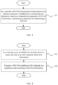
- FIG. 1 is a flowchart of an information processing method according to this embodiment of the present disclosure. As shown in FIG. 1 , the method includes the following step.
- Step 101 In a case that a PUCCH transmission format based on an interlace structure is scheduled for a terminal device, determine, based on a characteristic parameter of UCI to be fed back, a transmission parameter for transmitting a PUCCH.
- the transmission parameter includes at least one of the following:
- the PUCCH transmission format based on the interlace structure is scheduled for the terminal device and the PUCCH transmission format can support UCI of more than two bits, at least one of the foregoing information is determined.
- the characteristic parameter includes a bit quantity of the UCI, or, according to the invention as claimed, a bit quantity and a code rate of the UCI.
- a transmission parameter satisfying a preset condition when the PUCCH is transmitted is determined based on the characteristic parameter of the UCI.
- the preset condition is: a code rate of uplink information to be transmitted on the PUCCH is lower than or equal to a configured code rate; and the uplink information includes the UCI, or, according to the invention as claimed, the uplink information includes the UCI and a cyclic redundancy check (Cyclic redundancy check, CRC).
- the configured code rate may be configured by a network-side device.
- the UCI when the UCI is sent, if the number of UCI bits is greater than 2 and less than or equal to 11, an RM (Reed-Muller) coding mode is used for the UCI, there is no need to add a CRC, and a code rate of carried information represents the code rate of the UCI; or if the number of UCI bits is greater than 11, polar (polar) coding is used, a CRC bit needs to be added for checking, and a code rate of carried information is a code rate of the UCI plus the CRC.
- RM Random-Muller
- a base station configures PUCCH resource parameters, including a start interlace index S interlace PUCCH corresponding to an allocated interlace, the number N interlace PUCCH of interlaces, a start OFDM symbol position S symbol PUCCH , the number N symbol PUCCH of OFDM symbols, a spreading factor N SF PUCCH , an orthogonal sequence w n , a code rate r , and the like.
- RRC Radio Resource Control
- N interlace PUCCH if O UCI + O CRC > M PRB PUCCH ⁇ N sc , ctrl RB ⁇ N symbol PUCCH ⁇ Q m ⁇ r , the number of interlaces for transmitting the PUCCH by the UE is N interlace PUCCH , that is, the UE uses the number of interlaces configured by using RRC, to transmit the PUCCH.
- the determining a transmission parameter satisfying a preset condition for transmitting the PUCCH includes: determining the minimum number of OFDM symbols satisfying the preset condition.
- N is a positive integer: O UCI + O CRC ⁇ M PRB PUCCH ⁇ N sc , ctrl RB ⁇ N ⁇ Q m ⁇ r , N ⁇ N symbol PUCCH ;
- O UCI represents a bit quantity of the UCI;
- O CRC represents a bit quantity of the CRC;
- M PRB PUCCH represents the number of PRBs included in N interlace PUCCH interlaces configured by the network-side device, that is, the number of PRBs for transmitting the PUCCH;
- N N symbol PUCCH
- the number of OFDM symbols for transmitting the PUCCH by the UE is N symbol PUCCH , that is, the UE uses the number of OFDM symbols configured by using RRC, to transmit the PUCCH.
- the determining a transmission parameter satisfying a preset condition for transmitting the PUCCH includes: first obtaining a spreading factor set configured by the network-side device, where the spreading factor set may include one or more spreading factors; then determining, from the spreading factor set, a largest spreading factor satisfying the preset condition; and finally using the largest spreading factor as the spreading factor for transmitting the PUCCH.
- an orthogonal sequence corresponding to the largest spreading factor can be used as the orthogonal sequence for transmitting the PUCCH.
- the largest spreading factor satisfying the following inequality is used as the spreading factor for transmitting the PUCCH: O UCI + O CRC ⁇ M PRB PUCCH ⁇ N sc , ctrl RB ⁇ N symbol PUCCH ⁇ Q m ⁇ r / N SF PUCCH ,
- N SF PUCCH is a smallest spreading factor configured by the network-side device
- the spreading factor for transmitting the PUCCH by the UE is a smallest spreading factor configured by the network-side device, that is, the UE uses the smallest spreading factor configured by using RRC, to transmit the PUCCH.
- the method may be applied to the terminal device, for example, a mobile phone, a tablet personal computer (Tablet Personal Computer), a laptop computer (Laptop Computer), a personal digital assistant (personal digital assistant, PDA), a mobile Internet device (Mobile Internet Device, MID), or a wearable device (Wearable Device).
- the method may also be applied to the network-side device, for example, the base station.
- information required for actually transmitting the PUCCH can be adjusted based on the characteristic parameter of the UCI to be fed back, so that resource utilization is improved.
- FIG. 2 is a flowchart of an information processing method according to this embodiment of the present disclosure. The method is applied to a terminal device. As shown in FIG. 2 , the method includes the following steps.
- Step 201 In a case that a size of a BWP of the terminal device is larger than that of an LBT subband, obtain first information.
- the first information is used to indicate at least one of the following information: a resource configuration of a PUCCH and a transmission mode of the PUCCH.
- the transmission mode includes transmission in only one LBT subband or repeated transmission in different LBT subbands of a target bandwidth part.
- the target bandwidth part is the BWP of the terminal device, or the target bandwidth part is a subset of the BWP of the terminal device.
- the target bandwidth part may be configured by a network-side device, or indicated by a network-side device by using downlink control information (downlink control information, DCI), or determined by the terminal device according to a preset rule.
- DCI downlink control information
- Step 202 Transmit the PUCCH in different LBT subbands in a repetition mode according to the first information.
- the PUCCH can be repeatedly transmitted in each LBT subband.
- the first information is preconfigured or dynamically indicated by using higher layer signaling.
- the first information may include at least one of the following:
- FIG. 3 is a flowchart of an information processing method according to this embodiment of the present disclosure. The method is applied to a terminal device. As shown in FIG. 3 , the method includes the following steps.
- Step 301 Perform idle channel detection in a case that time domain resources for a first PUCCH and a second PUCCH overlap, where the first PUCCH corresponds to first UCI and the second PUCCH corresponds to second UCI.
- Step 302 Determine a transmission mode of the first UCI and the second UCI based on a result of the idle channel detection.
- This step includes: determining, based on a multiplexing rule, a multiplex PUCCH after the first UCI and the second UCI are multiplexed; and in a case that the multiplex PUCCH includes the first PUCCH or the second PUCCH, transmitting the first UCI and/or the second UCI based on the result of the idle channel detection, if either of the following conditions is satisfied:
- the performing idle channel detection includes: performing idle channel detection on the multiplex PUCCH before the multiplex PUCCH is transmitted or in an LBT subband in which the multiplex PUCCH is located; and the determining a transmission mode of the first UCI and the second UCI includes: in a case that a result of the idle channel detection before the multiplex PUCCH is transmitted or in the LBT subband in which the multiplex PUCCH is located indicates "idle", transmitting the first UCI and the second UCI on the multiplexed PUCCH.
- idle channel detection is performed before the first PUCCH or the second PUCCH, or in an LBT subband in which the first PUCCH or the second PUCCH is located; and in a case that a result of the idle channel detection before the first PUCCH or the second PUCCH or in the LBT subband the first PUCCH or the second PUCCH is located indicates "idle", the first UCI or the second UCI is transmitted.
- a network-side device performs blind detection. If the first PUCCH is received, the network-side device can determine that the first PUCCH carries the first UCI, or the first UCI and the second UCI; if the second PUCCH is received, the network-side device can determine that the first PUCCH carries the second UCI, or the first UCI and the second UCI; or if the third PUCCH is received, the network-side device can determine that the third PUCCH carries the first UCI and the second UCI.
- FIG. 4 is a flowchart of an information processing method according to this embodiment of the present disclosure. The method is applied to a network-side device. As shown in FIG. 4 , the method includes the following steps.
- Step 401 In a case that a size of a BWP of a terminal device is larger than that of an LBT subband, send first information to the terminal device.
- Step 402 Receive a PUCCH transmitted by the terminal device, where the PUCCH is transmitted by the terminal device in different LBT subbands of a target bandwidth part in a repetition mode according to the first information.
- the first information is used to indicate at least one of the following information: a resource configuration of the PUCCH and a transmission mode of the PUCCH; and the target bandwidth part is the BWP of the terminal device, or the target bandwidth part is a subset of the BWP of the terminal device.
- the method may further include: configuring the target bandwidth part, or indicating the target bandwidth part to the terminal device by using DCI.
- the first information includes any one of the following:
- An embodiment of the present disclosure provides a PUCCH information processing method in a case of an NR unlicensed band.
- the method mainly includes: when a PUCCH transmission format based on an interlace structure is scheduled for UE and the corresponding PUCCH transmission format is capable of supporting UCI of more than two bits, the UE determines at least one of the following based on a bit quantity and a code rate of UCI to be fed back:
- PUCCH resource configuration mode a base station indicates an interlace allocated to the PUCCH and an LBT subband in which the PUCCH is located, or an interlace allocated to the PUCCH (which may include a start interlace index and the number of interlaces), a start PRB index corresponding to the interlace, and the number of occupied PRBs (or a start PRB index and an end PRB index). If PUCCH transmission based on the interlaced resource block structure is scheduled for the UE, the UE transmits the PUCCH in N bandwidths of 20 MHz in a repetition mode based on the indication or configuration of the base station.
- the UE performs transmission based on an LBT result:
- the UE performs LBT before the PUCCH on which the UCI is multiplexed is transmitted or in the LBT subband in which the PUCCH is located. If it is detected that the channel is idle, the UE transmits the multiplexed UCI on the multiplexed PUCCH. If the UE performs LBT before transmitting the PUCCH on which the UCI is multiplexed or in the LBT subband in which the multiplex PUCCH is located and detects that the channel is busy, and the UE performs LBT before another PUCCH is transmitted or in the LBT subband in which the another PUCCH is located and detects that the channel is idle, the UE transmits the another PUCCH and UCI carried in the another PUCCH.
- the base station configures PUCCH resource parameters, including a start interlace index S interlace PUCCH corresponding to an allocated interlace, the number N interlace PUCCH of interlaces, a start OFDM symbol position S symbol PUCCH , the number N symbol PUCCH of OFDM symbols, a spreading factor N SF PUCCH , an orthogonal sequence w n , a code rate r , and the like.
- PUCCH resource parameters including a start interlace index S interlace PUCCH corresponding to an allocated interlace, the number N interlace PUCCH of interlaces, a start OFDM symbol position S symbol PUCCH , the number N symbol PUCCH of OFDM symbols, a spreading factor N SF PUCCH , an orthogonal sequence w n , a code rate r , and the like.
- the UE adjusts, based on the bit quantity and code rate of UCI to be sent, the number of interlaces of the PUCCH during transmission:
- the number of interlaces actually used by the UE for transmission is M, and indexes are S interlace PUCCH to S interlace PUCCH + M .
- the UE adjusts, based on the bit quantity and code rate of UCI to be sent, the number of OFDM symbols of the PUCCH during transmission: If the number of interlaces allocated to the PUCCH is greater than 1, the UE may adjust, based on the bit quantity and code rate of UCI to be fed back, the number of OFDM symbols used during actual transmission, where O UCI + O CRC ⁇ M PRB PUCCH ⁇ N sc , ctrl RB ⁇ N ⁇ Q m ⁇ r , where N ⁇ N symbol PUCCH .
- the number of PUCCH symbols used by the UE for transmission is N, and indexes are S symbol PUCCH to S symbol PUCCH + N .
- the UE adjusts, based on the bit quantity and code rate of UCI to be sent, a spreading factor (and an orthogonal sequence) used for the PUCCH during transmission:
- the UE may adjust interlaces during actual transmission, based on the bit quantity and code rate of UCI to be fed back, where O UCI + O CRC ⁇ M PRB PUCCH ⁇ N sc RB ⁇ N symbol PUCCH ⁇ Q m ⁇ r / N SF PUCCH .
- O UCI + O CRC ⁇ M PRB PUCCH ⁇ N sc RB ⁇ N symbol PUCCH ⁇ Q m ⁇ r / N SF PUCCH For a spreading factor, the UE tries from a largest spreading factor, and then a second largest spreading factor, until a largest spreading factor that satisfies the foregoing inequality.
- a UL BWP bandwidth activated by the UE is 80 MHz.
- transmission of the PUCCH is usually performed in a 20 MHz bandwidth.
- PUCCH transmission designs including a transmission sequence, an orthogonal sequence, rate matching, and the like, are all in one or more interlaces within 20 MHz.
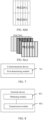
- transmitting the PUCCH in the entire BWP helps the UE preempt a channel and avoid unnecessary LBT. For example, as shown in FIG.
- two PUSCHs are scheduled for the UE, and each PUSCH occupies an 80 MHz bandwidth, but the two PUSCHs are not continuous in time domain, and a PUCCH is scheduled between the PUSCHs.
- the PUCCH channel bandwidth is 20 MHz, in other 60 MHz without the PUCCH, because there is a gap between the two PUSCHs, a channel resource may be preempted by another access point before a PUSCH 2 is transmitted, and consequently the PUSCH 2 cannot be transmitted.
- the UE may transmit the PUCCH in the entire BWP based on an instruction of the base station.
- the UE repeats the PUCCH transmitted in 20 MHz in different LBT subbands in a repetition mode.
- a PUCCH 1 is a channel state information (Channel State Information, CSI) PUCCH
- a PUCCH 2 is a scheduling request (Scheduling Request, SR) PUCCH.
- the two PUCCHs are located in a same LBT subband, but have different start symbols.
- the UE Based on a UCI multiplexing rule, when time domain resources for the CSI PUCCH and the SR PUCCH overlap, the UE multiplexes an SR on the CSI PUCCH, that is, the SR is transmitted on the PUCCH 1.
- the UE performs LBT before the PUCCH 1 is transmitted; and if detecting that the channel is idle, sends the PUCCH 1; or if detecting that the channel is busy, cannot transmit the PUCCH 1.
- the UE if the UE detects, before the PUCCH 1 is transmitted, that the channel is idle, the UE transmits the CSI and the SR on the PUCCH 1; if detecting that the channel is busy, the UE cannot transmit the PUCCH 1; if the SR is positive, the UE may continue to perform LBT before the PUCCH 2; if the UE detects that the channel is idle in this case, the UE transmits the positive SR (the UE does not transmit the CSI) through the PUCCH 2.
- the PUCCH 1 and the PUCCH 2 are located in different subbands. Therefore, the UE may perform LBT in different LBT subbands separately. If detecting, in the LBT subband in which the PUCCH 1 is located, that the channel is idle, the UE transmits the CSI and the SR on the PUCCH 1; if the subband in which the PUCCH 1 is located is busy, and the subband in which the PUCCH 2 is located is idle, the UE transmits the positive SR (without transmitting the CSI) through the PUCCH 2.
- the PUCCH 1 is a CSI PUCCH
- the PUCCH 2 is an SPS hybrid automatic repeat request acknowledgement (Hybrid automatic repeat request acknowledgement, HARQ-ACK) PUCCH.
- HARQ-ACK Hybrid automatic repeat request acknowledgement
- the UE If the UE detects, before the PUCCH 1 or in the LBT subband in which the PUCCH 1 is located, that the channel is idle, the UE transmits the CSI and the HARQ-ACK on the PUCCH 1; if the UE detects, before the PUCCH 1 or in the LBT subband in which the PUCCH 1 is located, that the channel is busy, and the UE detects, before the PUCCH 2 or in the LBT subband in which the PUCCH 2 is located, that the channel is idle, the UE transmits the HARQ-ACK (the UE does not transmit the CSI) on the PUCCH 2.
- the PUCCH 1 is a PUCCH carrying a HARQ-ACK corresponding to a physical downlink shared channel (Physical downlink shared channel, PDSCH) dynamically scheduled by a PDCCH
- the PUCCH 2 is a CSI PUCCH
- a PUCCH 3 is a PUCCH for multiplexing the HARQ-ACK and the CSI and determined based on a rule for multiplexing the HARQ-ACK and the CSI.
- the UE detects, before the PUCCH 3 is transmitted, that the channel is idle, the UE transmits the PUCCH 3 (carrying the HARQ-ACK and the CSI); if detecting that the channel is busy, the UE may continue to perform LBT before the PUCCH 2; if detecting, before the PUCCH 2 is transmitted, that the channel is idle, the UE may transmit the PUCCH 2 (carrying the CSI); if detecting that the channel is busy, the UE may continue to perform LBT before the PUCCH 1; if detecting, before the PUCCH 1 is transmitted, that the channel is idle, the UE may transmit the PUCCH 1 (carrying the HARQ-ACK).
- the UE detects a channel idle state before the multiplex PUCCH is transmitted or in the LBT subband in which the multiplex PUCCH is located. If it is detected that the channel is idle, the multiplex PUCCH and multiplexed UCI of the multiplex PUCCH are transmitted; if it is detected that the channel is busy, and if the first PUCCH or the second PUCCH and the multiplex PUCCH are located in different subbands, or a start symbol of the first PUCCH or the second PUCCH is later than a start symbol of the multiplexed PUCCH, the UE may perform idle channel detection in the subband in which the first PUCCH or the second PUCCH is located or before the first PUCCH or the second PUCCH is transmitted; if detecting that the channel is idle, the UE transmits the first PUCCH and the UCI of the first PUCCH, or the second PUCCH and the UCI of the second PUCCH.
- the UE performs, before the PUCCHs are transmitted, idle channel detection in a chronological order of the start symbols corresponding to the PUCCHs. If it is detected that the channel is idle before a PUCCH having an earliest start symbol is transmitted, the corresponding PUCCH and its UCI are transmitted; if it is detected that the channel is busy, idle channel detection is performed before a PUCCH after the PUCCH having the earliest start symbol; if it is detected that the channel is idle, the corresponding PUCCH and its UCI are transmitted, and so on, until a PUCCH having a latest start symbol.
- a method for PUCCH transmission in NRU including adaptive adjustment of PUCCH transmission resources (interlace, symbol, and spreading factor), a method for PUCCH transmission in a broadband case, and a method for PUCCH multiplexing, thereby improving resource utilization, facilitating system access in NRU, and improving effectiveness of system communication.
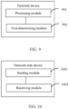
- a communications device in this embodiment of the present disclosure may include: a first determining module 701, configured to: in a case that a physical uplink control channel PUCCH transmission format based on an interlace structure is scheduled for the terminal device, determine, based on a characteristic parameter of UCI to be fed back, a transmission parameter for transmitting a PUCCH.
- a first determining module 701 configured to: in a case that a physical uplink control channel PUCCH transmission format based on an interlace structure is scheduled for the terminal device, determine, based on a characteristic parameter of UCI to be fed back, a transmission parameter for transmitting a PUCCH.
- the transmission parameter includes at least one of the following:
- the characteristic parameter includes a bit quantity of the UCI, or, according to the invention as claimed, a bit quantity and a code rate of the UCI.
- the first determining module 701 is specifically configured to determine, based on the characteristic parameter of the UCI, a transmission parameter satisfying a preset condition for transmitting the PUCCH, where the preset condition is: a code rate of uplink information to be transmitted on the PUCCH is lower than or equal to a configured code rate; and the uplink information includes the UCI, or, according to the invention as claimed, the uplink information includes the UCI and a CRC.
- the first determining module 701 is specifically configured to determine the minimum number of interlaces satisfying the preset condition; or determine the minimum number of OFDM symbols satisfying the preset condition.
- the first determining module 701 is specifically configured to: obtain a spreading factor set configured by a network-side device; determine, from the spreading factor set, a largest spreading factor satisfying the preset condition; and use the largest spreading factor as the spreading factor for transmitting the PUCCH.
- the first determining module is specifically configured to use an orthogonal sequence corresponding to the largest spreading factor as the orthogonal sequence for transmitting the PUCCH.
- the communications device in this embodiment of the present disclosure may be a terminal device or a network-side device.
- This embodiment is an embodiment of a communications device (terminal device or network-side device) corresponding to the information processing method in the foregoing Embodiment 1.
- the foregoing method embodiments are all applicable to the embodiment of the terminal device, with the same technical effect achieved.
- information required for actually transmitting the PUCCH can be adjusted based on the characteristic parameter of the UCI to be fed back, so that resource utilization is improved.
- a terminal device in this embodiment of the present disclosure may include: an obtaining module 801, configured to obtain first information in a case that a size of a BWP of the terminal device is larger than that of a listen before talk LBT subband; and a transmission module 802, configured to transmit a PUCCH in different LBT subbands of a target bandwidth part in a repetition mode according to the first information, where the first information is used to indicate at least one of the following information: a resource configuration of the PUCCH and a transmission mode of the PUCCH; and the target bandwidth part is the BWP of the terminal device, or the target bandwidth part is a subset of the BWP of the terminal device.
- the target bandwidth part is configured by a network-side device, or indicated by a network-side device by using downlink control information DCI, or obtained by the terminal device according to a preset rule.
- the first information is preconfigured or dynamically indicated by using higher layer signaling; and the first information includes at least one of the following:
- This embodiment is an embodiment of a terminal device corresponding to the information processing method in the foregoing Embodiment 2.
- the foregoing method embodiments are all applicable to the embodiment of the terminal device, with the same technical effect achieved.
- a terminal device in this embodiment of the present disclosure may include: a processing module 901, configured to perform idle channel detection in a case that time domain resources for a first PUCCH and a second PUCCH overlap, where the first PUCCH corresponds to first UCI and the second PUCCH corresponds to second UCI; and a first determining module 902, configured to determine a transmission mode of the first UCI and the second UCI based on a result of the idle channel detection.
- the first determining module 902 may include:
- the processing module 901 is configured to perform idle channel detection on the multiplex PUCCH before the multiplex PUCCH is transmitted or in an LBT subband in which the multiplex PUCCH is located; and the first determining module 902 is specifically configured to: in a case that a result of the idle channel detection before the multiplex PUCCH is transmitted or in the LBT subband in which the multiplex PUCCH is located indicates "idle", transmit the first UCI and the second UCI on the multiplexed PUCCH.
- the processing module 901 is configured to: in a case that a result of the idle channel detection before the multiplex PUCCH is transmitted or in the LBT subband in which the multiplex PUCCH is located indicates "busy”, perform idle channel detection before the first PUCCH or the second PUCCH is transmitted, or in an LBT subband in which the first PUCCH or the second PUCCH is located; and the first determining module 902 is specifically configured to: in a case that a result of the idle channel detection before the first PUCCH or the second PUCCH or inthe LBT subband the first PUCCH or the second PUCCH is located indicates "idle", transmit the first UCI or the second UCI.
- This embodiment is an embodiment of a terminal device corresponding to the information processing method in the foregoing Embodiment 3.
- the foregoing method embodiments are all applicable to the embodiment of the terminal device, with the same technical effect achieved.
- a network-side device in this embodiment of the present disclosure may include:
- the network-side device may further include a processing module, configured to configure the target bandwidth part, or indicate the target bandwidth part to the terminal device by using DCI.
- a processing module configured to configure the target bandwidth part, or indicate the target bandwidth part to the terminal device by using DCI.
- the first information includes any one of the following:
- This embodiment is an embodiment of a network-side device corresponding to the information processing method in the foregoing Embodiment 4.
- the foregoing method embodiments are all applicable to the embodiment of the terminal device, with the same technical effect achieved.
- FIG. 11 is a schematic structural diagram of hardware of a terminal device for implementing the embodiments of the present disclosure.
- the terminal device 1100 includes but is not limited to components such as a radio frequency unit 1101, a network module 1102, an audio output unit 1103, an input unit 1104, a sensor 1105, a display unit 1106, a user input unit 1107, an interface unit 1108, a memory 1109, a processor 1110, and a power supply 1111.
- a radio frequency unit 1101 such as a radio frequency unit 1101, a network module 1102, an audio output unit 1103, an input unit 1104, a sensor 1105, a display unit 1106, a user input unit 1107, an interface unit 1108, a memory 1109, a processor 1110, and a power supply 1111.
- a person skilled in the art can understand that the structure of the terminal device shown in FIG. 11 does not constitute any limitation on the terminal device.
- the terminal device may include more or fewer components than those shown in the figure, or a combination of some components, or the components disposed
- the terminal device includes but is not limited to a mobile phone, a tablet computer, a laptop computer, a palmtop computer, an in-vehicle mobile terminal, a wearable device, a pedometer, and the like.
- the processor 1110 is configured to perform the steps of the information processing method in Embodiment 1, with the same technical effect achieved. Alternatively, the processor 1110 is configured to perform the steps of the information processing method in Embodiment 2, with the same technical effect achieved. Alternatively, the processor 1110 is configured to perform the steps of the information processing method in Embodiment 3, with the same technical effect achieved.
- the radio frequency unit 1101 may be configured to receive and send information, or to receive and send a signal in a call process, and specifically, after receiving downlink data from a base station, send the downlink data to the processor 1110 for processing; and also send uplink data to the base station.
- the radio frequency unit 1101 includes but is not limited to an antenna, at least one amplifier, a transceiver, a coupler, a low noise amplifier, a duplexer, and the like.
- the radio frequency unit 1101 may also communicate with a network and other devices via a wireless communications system.
- the terminal device provides a user with wireless broadband internet access through the network module 1102, for example, helping the user to transmit and receive e-mails, browse web pages, and access streaming media.
- the audio output unit 1103 may convert audio data received by the radio frequency unit 1101 or the network module 1102 or stored in the memory 1109 into an audio signal and output the audio signal as a sound.
- the audio output unit 1103 may further provide audio output (for example, a call signal received sound or a message received sound) related to a specific function performed by the terminal device 1100.
- the audio output unit 1103 includes a speaker, a buzzer, a receiver, and the like.
- the input unit 1104 is configured to receive an audio or video signal.
- the input unit 1104 may include a graphics processing unit (Graphics Processing Unit, GPU) 11041 and a microphone 11042.
- the graphics processing unit 11041 processes image data of a still picture or video obtained by an image capture apparatus (such as a camera) in a video capture mode or an image capture mode.
- a processed image frame may be displayed on the display unit 1106.
- the image frame processed by the graphics processing unit 11041 may be stored in the memory 1109 (or another storage medium) or be sent by the radio frequency unit 1101 or the network module 1102.
- the microphone 11042 is capable of receiving sounds and processing such sounds into audio data.
- the processed audio data can be converted into a format that can be sent to a mobile communication base station through the radio frequency unit 1101 in a telephone call mode, for outputting.
- the terminal device 1100 may further include at least one sensor 1105, for example, an optical sensor, a motion sensor, and other sensors.
- the optical sensor includes an ambient light sensor and a proximity sensor.
- the ambient light sensor may adjust luminance of the display panel 11061 based on brightness of ambient light
- the proximity sensor may turn off the display panel 11061 and/or backlight when the terminal device 1100 moves close to an ear.
- an accelerometer sensor can detect magnitudes of accelerations in all directions (usually three axes), can detect a magnitude and a direction of gravity when the mobile phone is in a static state, and can be applied to posture recognition (such as screen switching between portrait and landscape, related games, and magnetometer posture calibration) of the terminal device, functions related to vibration recognition (such as pedometer and tapping), and the like.
- the sensor 1105 may also include a fingerprint sensor, a pressure sensor, an iris sensor, a molecular sensor, a gyroscope, a barometer, a hygrometer, a thermometer, an infrared sensor, and the like. Details are not described herein.
- the display unit 1106 is configured to display information input by the user or information provided to the user.
- the display unit 1106 may include the display panel 11061, and the display panel 11061 may be configured in a form of a liquid crystal display (Liquid Crystal Display, LCD), an organic light-emitting diode (Organic Light-Emitting Diode, OLED), or the like.
- LCD Liquid Crystal Display
- OLED Organic Light-Emitting Diode
- the user input unit 1107 may be configured to receive input digit or character information and generate key signal input related to user setting and function control of the terminal device.
- the user input unit 1107 includes a touch panel 11071 and other input devices 11072.
- the touch panel 11071 is also referred to as a touchscreen and can collect a touch operation (such as an operation performed by the user on the touch panel 11071 or near the touch panel 11071 with a finger or by using any proper object or accessory such as a stylus) of the user on or near the touch panel 11071.
- the touch panel 11071 may include two parts: a touch detection apparatus and a touch controller.
- the touch detection apparatus detects a touch azimuth of a user, detects a signal brought by a touch operation, and transmits the signal to the touch controller.
- the touch controller receives touch information from the touch detection apparatus, converts the touch information into touchpoint coordinates, and sends the touchpoint coordinates to the processor 1110, and receives a command sent by the processor 1110 and executes the command.
- the touch panel 11071 may be implemented in a plurality of forms, for example, as a resistive, capacitive, infrared, or surface acoustic wave touch panel.
- the user input unit 1107 may further include the other input devices 11072 in addition to the touch panel 11071.
- the other input devices 11072 may include but are not limited to a physical keyboard, a function key (such as a volume control key or a switch key), a trackball, a mouse, and a joystick. Details are not described herein.
- the touch panel 11071 may cover the display panel 11061.
- the touch panel 11071 transmits the touch operation to the processor 1110 to determine a type of a touch event. Then, the processor 1110 provides a corresponding visual output on the display panel 11061 based on the type of the touch event.
- the touch panel 11071 and the display panel 11061 act as two independent parts to implement input and output functions of the terminal device, in some embodiments, the touch panel 11071 and the display panel 11061 may be integrated to implement the input and output functions of the terminal device. This is not specifically limited herein.
- the interface unit 1108 is an interface between an external apparatus and the terminal device 1100.
- an external apparatus may include a wired or wireless headset port, an external power supply (or a battery charger) port, a wired or wireless data port, a memory port, a port for connecting an apparatus with an identification module, an audio input/output (I/O) port, a video I/O port, an earphone port, and the like.
- the interface unit 1108 may be configured to receive an input (for example, data information or power) from an external apparatus and transmit the received input to one or more elements within the terminal device 1100, or may be configured to transmit data between the terminal device 1100 and the external apparatus.
- the memory 1109 may be configured to store software programs and various data.
- the memory 1109 may primarily include a program storage area and a data storage area.
- the program storage area may store an operating system, an application program (such as an audio play function and an image play function) required by at least one function, and the like.
- the data storage area may store data (such as audio data and a phone book) created based on use of the mobile phone.
- the memory 1109 may include a high-speed random access memory, and may further include a non-volatile memory such as a disk storage device, a flash memory device, or another volatile solid-state storage device.
- the processor 1110 is a control center of the terminal device, uses various interfaces and lines to connect parts of the entire terminal device, and executes various functions and processing data of the terminal device by running or executing software programs and/or modules stored in the memory 1109 and invoking data stored in the memory 1109, so as to perform overall monitoring on the terminal device.
- the processor 1110 may include one or more processing units.
- the processor 1110 may integrate an application processor and a modem processor.
- the application processor mainly processes the operating system, a user interface, the application program, and the like.
- the modem processor mainly processes wireless communication. It can be understood that the modem processor may alternatively be not integrated in the processor 1110.
- the terminal device 1100 may further include a power supply 1111 (such as a battery) that supplies power to components.
- a power supply 1111 may be logically connected to the processor 1110 through a power management system. In this way, functions such as charge management, discharge management, and power consumption management are implemented by using the power management system.
- the terminal device 1100 includes some functional modules that are not shown. Details are not described herein.
- an embodiment of the present disclosure further provides a terminal device, including a processor 1110, a memory 1109, and a computer program stored in the memory 1109 and capable of running on the processor 1110.
- a terminal device including a processor 1110, a memory 1109, and a computer program stored in the memory 1109 and capable of running on the processor 1110.
- the computer program is executed by the processor 1110, the processes of the foregoing embodiment of the information processing method are implemented, with the same technical effect achieved. To avoid repetition, details are not described again herein.
- a network-side device in an embodiment of the present disclosure includes a processor 1200, configured to read a program in a memory 1220 to perform the following process:
- a bus architecture may include any quantity of interconnect buses and bridges, specifically for interconnecting various circuits of one or more processors represented by the processor 1200 and a memory represented by the memory 1220.
- the bus architecture may further interconnect various other circuits such as a peripheral device, a voltage regulator, and a power management circuit. These are all well known in the art, and therefore are not further described in this specification.
- the bus interface provides an interface.
- the transceiver 1210 may be a plurality of components, that is, the transceiver 1210 includes a transmitter and a receiver, and provides a unit for communicating with various other apparatuses on a transmission medium.
- the processor 1200 is responsible for management of the bus architecture and general processing, and the memory 1220 is capable of storing data that is used by the processor 1200 during operation.
- the processor 1200 is responsible for management of the bus architecture and general processing, and the memory 1220 is capable of storing data that is used by the processor 1200 during operation.
- the processor 1200 is further configured to read the computer program to perform the following step: configuring the target bandwidth part, or indicating the target bandwidth part to the terminal device by using DCI.
- the first information includes any one of the following:
- An embodiment of the present disclosure further provides a computer-readable storage medium, where a computer program is stored in the computer-readable storage medium.
- a computer program is stored in the computer-readable storage medium.
- the computer-readable storage medium is, for example, a read-only memory (Read-Only Memory, ROM), a random access memory (Random Access Memory, RAM), a magnetic disk, or an optical disc.
- the computer software product is stored in a storage medium (for example, a ROM/RAM, a magnetic disk, or an optical disc), and includes several instructions for instructing a terminal device (which may be a mobile phone, a computer, a server, an air conditioner, a network device, or the like) to perform the method described in the embodiments of the present disclosure.
- a storage medium for example, a ROM/RAM, a magnetic disk, or an optical disc
- a terminal device which may be a mobile phone, a computer, a server, an air conditioner, a network device, or the like
Landscapes
- Engineering & Computer Science (AREA)
- Signal Processing (AREA)
- Computer Networks & Wireless Communication (AREA)
- Quality & Reliability (AREA)
- Mobile Radio Communication Systems (AREA)
Claims (12)
- Verfahren zur Informationsverarbeitung, das Folgendes aufweist:in einem Fall, dass ein Übertragungsformat eines physikalischen Uplink-Steuerkanals, PUCCH-Übertragungsformat, basierend auf einer Interlace-Struktur für ein Endgerät geplant ist, Bestimmen (101) eines Übertragungsparameters zum Übertragen eines PUCCH basierend auf einem charakteristischen Parameter von Uplink-Steuerinformationen, UCI, die zurückgespeist werden sollen;wobei der charakteristische Parameter eine Bitmenge und eine Coderate der UCI aufweist;dadurch gekennzeichnet, dass der Übertragungsparameter die Anzahl von Interlaces zum Übertragen des PUCCH aufweist;wobei das Bestimmen (101) eines Übertragungsparameters zum Übertragen eines PUCCH basierend auf einem charakteristischen Parameter von Uplink-Steuerinformationen, UCI, die zurückgespeist werden sollen, Folgendes aufweist:Bestimmen eines Übertragungsparameters, der einer voreingestellten Bedingung zum Übertragen der PUCCH entspricht, basierend auf dem charakteristischen Parameter der UCI, wobeidie voreingestellte Bedingung ist: eine Coderate der auf dem PUCCH zu übertragenden Uplink-Informationen niedriger als eine konfigurierte Coderate oder gleich dieser ist; unddie Uplink-Informationen die UCI und eine zyklische Redundanzprüfung, CRC, aufweisen.
- Verfahren nach Anspruch 1, wobei der Übertragungsparameter ferner Folgendes aufweist:die Anzahl von Symbolen des orthogonalen Frequenzmultiplexverfahrens, OFDM-Symbolen, zum Übertragen des PUCCH; und/odereinen Spreizfaktor zum Übertragen des PUCCH; und/odereine orthogonale Sequenz zum Übertragen des PUCCH.
- Verfahren nach Anspruch 1, wobei das Bestimmen eines Übertragungsparameters, der einer voreingestellten Bedingung zum Übertragen des PUCCH entspricht, Folgendes aufweist:Bestimmen der minimalen Anzahl von Interfaces, die der voreingestellten Bedingung entsprechen; oderBestimmen der minimalen Anzahl von OFDM-Symbolen, die der voreingestellten Bedingung entsprechen.
- Verfahren nach Anspruch 1, wobei das Bestimmen eines Übertragungsparameters, der einer voreingestellten Bedingung zum Übertragen des PUCCH entspricht, Folgendes aufweist:Erhalten eines Spreizfaktorsatzes, der von einem netzwerkseitigen Gerät konfiguriert ist;Bestimmen, aus dem Spreizfaktorsatz, eines größten Spreizfaktors, der der voreingestellten Bedingung entspricht; undVerwenden des größten Spreizfaktors als Spreizfaktor zum Übertragen des PUCCH.
- Kommunikationsgerät, wobei das Kommunikationsgerät ein Endgerät oder ein netzwerkseitiges Gerät ist und Folgendes aufweist:ein erstes Bestimmungsmodul (701), das konfiguriert ist, um: in einem Fall, dass ein Übertragungsformat eines physikalischen Uplink-Steuerkanals, PUCCH-Übertragungsformat, basierend auf einer Interface-Struktur für das Endgerät geplant ist, basierend auf einem charakteristischen Parameter von UCI, die zurückgespeist werden sollen, einen Übertragungsparameter zum Übertragen eines PUCCH zu bestimmen;wobei der charakteristische Parameter eine Bitmenge und eine Coderate der UCI aufweist;dadurch gekennzeichnet, dass der Übertragungsparameter die Anzahl von Interlaces zum Übertragen des PUCCH aufweist;wobei das erste Bestimmungsmodul (701) konfiguriert ist, um:basierend auf dem charakteristischen Parameter der UCI, einen Übertragungsparameter, der einer voreingestellten Bedingung zum Übertragen des PUCCH entspricht, zu bestimmen, wobeidie voreingestellte Bedingung ist: eine Coderate von auf dem PUCCH zu übertragenden Uplink-Informationen niedriger als eine konfigurierte Coderate oder gleich dieser ist; unddie Uplink-Informationen die UCI und eine zyklische Redundanzprüfung, CRC, aufweisen.
- Kommunikationsgerät nach Anspruch 5, wobei der Übertragungsparameter ferner Folgendes aufweist:die Anzahl von Symbolen des orthogonalen Frequenzmultiplexverfahrens, OFDM-Symbolen, zum Übertragen des PUCCH; und/odereinen Spreizfaktor zum Übertragen des PUCCH; und/odereine orthogonale Sequenz zum Übertragen des PUCCH.
- Kommunikationsgerät nach Anspruch 5, wobei das erste Bestimmungsmodul (701) konfiguriert ist, um:die minimale Anzahl von Interlaces zu bestimmen, die der voreingestellten Bedingung entsprechen; oderdie minimale Anzahl von OFDM-Symbolen zu bestimmen, die der voreingestellten Bedingung entsprechen.
- Kommunikationsgerät nach Anspruch 5, wobei das erste Bestimmungsmodul (701) konfiguriert ist, um:einen Spreizfaktorsatz zu erhalten, der von einem netzwerkseitigen Gerät konfiguriert ist;aus dem Spreizfaktorsatz einen größten Spreizfaktor zu bestimmen, der die voreingestellte Bedingung erfüllt; undden größten Spreizfaktor als den Spreizfaktor zum Übertragen des PUCCH zu verwenden.
- Computerlesbares Speichermedium, wobei das computerlesbare Speichermedium Anweisungen speichert, die, wenn sie von einem Computer ausgeführt werden, den Computer veranlassen, Folgendes auszuführen:in einem Fall, dass ein Übertragungsformat eines physikalischen Uplink-Steuerkanals, PUCCH-Übertragungsformat, basierend auf einer Interlace-Struktur für ein Endgerät geplant ist, Bestimmen (101) eines Übertragungsparameters zum Übertragen eines PUCCH basierend auf einem charakteristischen Parameter von Uplink-Steuerinformationen, UCI, die zurückgespeist werden sollen;wobei der charakteristische Parameter eine Bitmenge und eine Coderate der UCI aufweist;dadurch gekennzeichnet, dass der Übertragungsparameter die Anzahl der Interlaces zum Übertragen des PUCCH aufweist;wobei das Computerprogramm ferner von einem Prozessor ausgeführt wird, um Folgendes zu auszuführen:Bestimmen eines Übertragungsparameters, der einer voreingestellten Bedingung zum Übertragen des PUCCH entspricht, basierend auf dem charakteristischen Parameter der UCI, wobeidie voreingestellte Bedingung ist: eine Coderate der auf dem PUCCH zu übertragenden Uplink-Informationen niedriger als eine konfigurierte Coderate oder gleich dieser ist; unddie Uplink-Informationen die UCI und eine zyklische Redundanzprüfung, CRC, aufweisen.
- Computerlesbares Speichermedium nach Anspruch 9, wobei der Übertragungsparameter ferner Folgendes aufweist:die Anzahl von Symbolen des orthogonalen Frequenzmultiplexverfahrens, OFDM-Symbolen, zum Übertragen des PUCCH; und/odereinen Spreizfaktor zum Übertragen des PUCCH; und/odereine orthogonale Sequenz zum Übertragen des PUCCH.
- Computerlesbares Speichermedium nach Anspruch 9, wobei die Anweisungen ferner den Computer veranlassen, Folgendes auszuführen:Bestimmen der minimalen Anzahl von Interfaces, die der voreingestellten Bedingung entsprechen; oderBestimmen der minimalen Anzahl von OFDM-Symbolen, die der voreingestellten Bedingung entsprechen.
- Computerlesbares Speichermedium nach Anspruch 9, wobei die Anweisungen den Computer ferner veranlassen, Folgendes auszuführen:Erhalten eines Spreizfaktorsatzes, der von einem netzwerkseitigen Gerät konfiguriert ist;Bestimmen eines größten Spreizfaktors, der der voreingestellten Bedingung entspricht, aus dem Spreizfaktorsatz; undVerwenden des größten Spreizfaktors als Spreizfaktor zum Übertragen des PUCCH.
Applications Claiming Priority (2)
| Application Number | Priority Date | Filing Date | Title |
|---|---|---|---|
| CN201910748114.7A CN111835487B (zh) | 2019-08-13 | 2019-08-13 | 一种信息处理方法、设备及计算机可读存储介质 |
| PCT/CN2020/108227 WO2021027780A1 (zh) | 2019-08-13 | 2020-08-10 | 信息处理方法、设备及计算机可读存储介质 |
Publications (3)
| Publication Number | Publication Date |
|---|---|
| EP4016903A1 EP4016903A1 (de) | 2022-06-22 |
| EP4016903A4 EP4016903A4 (de) | 2022-10-05 |
| EP4016903B1 true EP4016903B1 (de) | 2024-09-18 |
Family
ID=72912584
Family Applications (1)
| Application Number | Title | Priority Date | Filing Date |
|---|---|---|---|
| EP20852242.5A Active EP4016903B1 (de) | 2019-08-13 | 2020-08-10 | Informationsverarbeitungsverfahren, vorrichtung und computerlesbares speichermedium |
Country Status (10)
| Country | Link |
|---|---|
| US (1) | US20220174701A1 (de) |
| EP (1) | EP4016903B1 (de) |
| JP (1) | JP7307269B2 (de) |
| KR (1) | KR102886613B1 (de) |
| CN (1) | CN111835487B (de) |
| BR (1) | BR112022002668A2 (de) |
| ES (1) | ES2991870T3 (de) |
| HU (1) | HUE068451T2 (de) |
| PT (1) | PT4016903T (de) |
| WO (1) | WO2021027780A1 (de) |
Families Citing this family (1)
| Publication number | Priority date | Publication date | Assignee | Title |
|---|---|---|---|---|
| EP4510731A4 (de) * | 2022-04-14 | 2025-06-18 | Beijing Xiaomi Mobile Software Co., Ltd. | Ressourcenkonfigurationsverfahren und vorrichtung dafür |
Family Cites Families (21)
| Publication number | Priority date | Publication date | Assignee | Title |
|---|---|---|---|---|
| US9949275B2 (en) * | 2013-10-01 | 2018-04-17 | Qualcomm Incorporated | Physical uplink control management in LTE/LTE-A systems with unlicensed spectrum |
| US10033505B2 (en) * | 2014-07-31 | 2018-07-24 | Qualcomm Incorporated | Transmission of uplink control channels over an unlicensed radio frequency spectrum band |
| US10827491B2 (en) * | 2014-10-07 | 2020-11-03 | Qualcomm Incorporated | Techniques for transmitting a sounding reference signal or scheduling request over an unlicensed radio frequency spectrum band |
| US9918302B2 (en) | 2014-12-12 | 2018-03-13 | Qualcomm Incorporated | Techniques for managing transmissions in an unlicensed radio frequency spectrum band |
| US9949169B2 (en) * | 2015-05-22 | 2018-04-17 | Qualcomm Incorporated | Control flow enhancements for LTE-unlicensed |
| JP6608051B2 (ja) * | 2015-07-10 | 2019-11-20 | エルジー エレクトロニクス インコーポレイティド | 非免許帯域及びキャリア結合を支援する無線接続システムにおいてデータバースト送信方法及び装置 |
| CN106470089B (zh) * | 2015-08-14 | 2021-05-11 | 中兴通讯股份有限公司 | 一种上行控制信息的发送方法及装置 |
| CN106559198B (zh) * | 2015-09-25 | 2019-09-17 | 电信科学技术研究院 | 一种基于pucch的上行控制信息传输方法及装置 |
| US10368348B2 (en) * | 2015-11-18 | 2019-07-30 | Qualcomm Incorporated | Physical control channel signaling on a shared communication medium |
| ES3013564T3 (en) * | 2015-12-07 | 2025-04-14 | Ericsson Telefon Ab L M | Uplink control channel configuration for unlicensed carriers |
| CN107026723B (zh) * | 2016-02-02 | 2020-10-09 | 电信科学技术研究院 | 一种传输上行控制信息的方法和设备 |
| US10856282B2 (en) * | 2016-02-22 | 2020-12-01 | Apple Inc. | Interlaces allocation and indication |
| CN112332944A (zh) | 2016-03-11 | 2021-02-05 | 苹果公司 | 上行链路控制信息的码分复用 |
| CN107241802B (zh) * | 2016-03-29 | 2022-12-02 | 中兴通讯股份有限公司 | 上行控制信息uci的发送方法及装置 |
| WO2017217799A1 (ko) * | 2016-06-16 | 2017-12-21 | 엘지전자 주식회사 | 무선 통신 시스템에서 물리 상향링크 제어 채널 송수신 방법 및 이를 지원하는 장치 |
| CN109275191B (zh) * | 2017-07-18 | 2021-03-30 | 华为技术有限公司 | 一种传输方法及其装置 |
| CN109842431B (zh) * | 2017-11-16 | 2020-11-13 | 维沃移动通信有限公司 | 传输反馈信息的方法、终端设备和网络设备 |
| CN110035535A (zh) * | 2018-01-12 | 2019-07-19 | 华为技术有限公司 | 一种上行控制信息的传输方法、接入网设备以及终端设备 |
| CN110049559B (zh) * | 2018-01-17 | 2021-11-12 | 维沃移动通信有限公司 | 侦听指示方法、终端及网络设备 |
| JP2020521365A (ja) * | 2018-02-14 | 2020-07-16 | エルジー エレクトロニクス インコーポレイティド | 非免許帯域を支援する無線通信システムにおいて端末と基地局の間の上りリンク信号を送受信する方法及びそれを支援する装置 |
| EP3949238B1 (de) * | 2019-03-29 | 2025-07-16 | Apple Inc. | Ressourcenzuweisung und verbesserungen der benutzermultiplexkapazität für interlace-basierte physikalische uplink-steuerkanalformate in neuem unlizenziertem funk (nr) |
-
2019
- 2019-08-13 CN CN201910748114.7A patent/CN111835487B/zh active Active
-
2020
- 2020-08-10 JP JP2022508946A patent/JP7307269B2/ja active Active
- 2020-08-10 EP EP20852242.5A patent/EP4016903B1/de active Active
- 2020-08-10 PT PT208522425T patent/PT4016903T/pt unknown
- 2020-08-10 WO PCT/CN2020/108227 patent/WO2021027780A1/zh not_active Ceased
- 2020-08-10 HU HUE20852242A patent/HUE068451T2/hu unknown
- 2020-08-10 BR BR112022002668A patent/BR112022002668A2/pt unknown
- 2020-08-10 ES ES20852242T patent/ES2991870T3/es active Active
- 2020-08-10 KR KR1020227008214A patent/KR102886613B1/ko active Active
-
2022
- 2022-02-11 US US17/670,293 patent/US20220174701A1/en active Pending
Also Published As
| Publication number | Publication date |
|---|---|
| JP7307269B2 (ja) | 2023-07-11 |
| EP4016903A4 (de) | 2022-10-05 |
| PT4016903T (pt) | 2024-10-21 |
| ES2991870T3 (es) | 2024-12-05 |
| US20220174701A1 (en) | 2022-06-02 |
| EP4016903A1 (de) | 2022-06-22 |
| BR112022002668A2 (pt) | 2022-05-10 |
| HUE068451T2 (hu) | 2024-12-28 |
| KR102886613B1 (ko) | 2025-11-13 |
| KR20220046641A (ko) | 2022-04-14 |
| WO2021027780A1 (zh) | 2021-02-18 |
| CN111835487A (zh) | 2020-10-27 |
| JP2022544520A (ja) | 2022-10-19 |
| CN111835487B (zh) | 2022-07-01 |
Similar Documents
| Publication | Publication Date | Title |
|---|---|---|
| KR102903299B1 (ko) | Uci의 전송 방법, 수신 방법, 단말 및 네트워크 장치 | |
| US12207268B2 (en) | Method for transmitting uplink control information, method for receiving uplink control information, terminal, and network-side device | |
| US11968012B2 (en) | Information transmission method and terminal | |
| US11917685B2 (en) | Frequency domain resource allocation method, terminal, and network device | |
| EP3876645B1 (de) | Uplink-übertragungsverfahren, benutzervorrichtung und netzwerkseitige vorrichtung | |
| CN111835489B (zh) | 一种传输方法、配置方法、终端及网络侧设备 | |
| CN111182634B (zh) | 数据传输方法、终端及网络设备 | |
| EP4096326A1 (de) | Verfahren zur verarbeitung von frequenzdomänen, verfahren zur konfigurierung von frequenzdomänen und zugehörige vorrichtung | |
| CN111800240B (zh) | 信息传输方法、装置、终端、设备及介质 | |
| WO2020192547A1 (zh) | 信息传输、接收方法、终端及网络侧设备 | |
| CN111130713B (zh) | 一种传输方法、发送端设备、接收端设备及网络侧设备 | |
| CN111800880B (zh) | 上行控制信息的传输方法、终端设备及存储介质 | |
| CN111615197A (zh) | 资源调整方法及设备 | |
| EP4016903B1 (de) | Informationsverarbeitungsverfahren, vorrichtung und computerlesbares speichermedium | |
| WO2019214420A1 (zh) | 业务调度方法、终端及网络设备 | |
| HK40067340A (en) | Information processing method, device and computer-readable storage medium | |
| HK40067340B (en) | Information processing method, device and computer-readable storage medium | |
| HK40047080B (en) | Information transmission method and terminal | |
| CN113498202A (zh) | 一种非授权频段传输的方法及通信设备 | |
| HK40047080A (en) | Information transmission method and terminal | |
| HK40076955A (en) | Frequency domain resource processing method, frequency domain resource configuration method and related device | |
| HK40062035A (en) | Method, terminal and network equipment for frequency domain resource allocation |
Legal Events
| Date | Code | Title | Description |
|---|---|---|---|
| STAA | Information on the status of an ep patent application or granted ep patent |
Free format text: STATUS: THE INTERNATIONAL PUBLICATION HAS BEEN MADE |
|
| PUAI | Public reference made under article 153(3) epc to a published international application that has entered the european phase |
Free format text: ORIGINAL CODE: 0009012 |
|
| STAA | Information on the status of an ep patent application or granted ep patent |
Free format text: STATUS: REQUEST FOR EXAMINATION WAS MADE |
|
| 17P | Request for examination filed |
Effective date: 20220301 |
|
| AK | Designated contracting states |
Kind code of ref document: A1 Designated state(s): AL AT BE BG CH CY CZ DE DK EE ES FI FR GB GR HR HU IE IS IT LI LT LU LV MC MK MT NL NO PL PT RO RS SE SI SK SM TR |
|
| REG | Reference to a national code |
Ref country code: HK Ref legal event code: DE Ref document number: 40067340 Country of ref document: HK |
|
| A4 | Supplementary search report drawn up and despatched |
Effective date: 20220905 |
|
| RIC1 | Information provided on ipc code assigned before grant |
Ipc: H04L 1/16 20060101ALI20220830BHEP Ipc: H04L 1/00 20060101ALI20220830BHEP Ipc: H04W 72/04 20090101ALI20220830BHEP Ipc: H04L 5/00 20060101AFI20220830BHEP |
|
| DAV | Request for validation of the european patent (deleted) | ||
| DAX | Request for extension of the european patent (deleted) | ||
| GRAP | Despatch of communication of intention to grant a patent |
Free format text: ORIGINAL CODE: EPIDOSNIGR1 |
|
| STAA | Information on the status of an ep patent application or granted ep patent |
Free format text: STATUS: GRANT OF PATENT IS INTENDED |
|
| INTG | Intention to grant announced |
Effective date: 20240405 |
|
| GRAS | Grant fee paid |
Free format text: ORIGINAL CODE: EPIDOSNIGR3 |
|
| GRAA | (expected) grant |
Free format text: ORIGINAL CODE: 0009210 |
|
| STAA | Information on the status of an ep patent application or granted ep patent |
Free format text: STATUS: THE PATENT HAS BEEN GRANTED |
|
| AK | Designated contracting states |
Kind code of ref document: B1 Designated state(s): AL AT BE BG CH CY CZ DE DK EE ES FI FR GB GR HR HU IE IS IT LI LT LU LV MC MK MT NL NO PL PT RO RS SE SI SK SM TR |
|
| REG | Reference to a national code |
Ref country code: GB Ref legal event code: FG4D |
|
| REG | Reference to a national code |
Ref country code: CH Ref legal event code: EP |
|
| REG | Reference to a national code |
Ref country code: DE Ref legal event code: R096 Ref document number: 602020038100 Country of ref document: DE |
|
| REG | Reference to a national code |
Ref country code: IE Ref legal event code: FG4D |
|
| REG | Reference to a national code |
Ref country code: NL Ref legal event code: FP |
|
| REG | Reference to a national code |
Ref country code: PT Ref legal event code: SC4A Ref document number: 4016903 Country of ref document: PT Date of ref document: 20241021 Kind code of ref document: T Free format text: AVAILABILITY OF NATIONAL TRANSLATION Effective date: 20241015 |
|
| REG | Reference to a national code |
Ref country code: ES Ref legal event code: FG2A Ref document number: 2991870 Country of ref document: ES Kind code of ref document: T3 Effective date: 20241205 |
|
| REG | Reference to a national code |
Ref country code: HU Ref legal event code: AG4A Ref document number: E068451 Country of ref document: HU |
|
| REG | Reference to a national code |
Ref country code: LT Ref legal event code: MG9D |
|
| PG25 | Lapsed in a contracting state [announced via postgrant information from national office to epo] |
Ref country code: NO Free format text: LAPSE BECAUSE OF FAILURE TO SUBMIT A TRANSLATION OF THE DESCRIPTION OR TO PAY THE FEE WITHIN THE PRESCRIBED TIME-LIMIT Effective date: 20241218 |
|
| PG25 | Lapsed in a contracting state [announced via postgrant information from national office to epo] |
Ref country code: GR Free format text: LAPSE BECAUSE OF FAILURE TO SUBMIT A TRANSLATION OF THE DESCRIPTION OR TO PAY THE FEE WITHIN THE PRESCRIBED TIME-LIMIT Effective date: 20241219 Ref country code: FI Free format text: LAPSE BECAUSE OF FAILURE TO SUBMIT A TRANSLATION OF THE DESCRIPTION OR TO PAY THE FEE WITHIN THE PRESCRIBED TIME-LIMIT Effective date: 20240918 |
|
| PG25 | Lapsed in a contracting state [announced via postgrant information from national office to epo] |
Ref country code: BG Free format text: LAPSE BECAUSE OF FAILURE TO SUBMIT A TRANSLATION OF THE DESCRIPTION OR TO PAY THE FEE WITHIN THE PRESCRIBED TIME-LIMIT Effective date: 20240918 |
|
| PG25 | Lapsed in a contracting state [announced via postgrant information from national office to epo] |
Ref country code: LV Free format text: LAPSE BECAUSE OF FAILURE TO SUBMIT A TRANSLATION OF THE DESCRIPTION OR TO PAY THE FEE WITHIN THE PRESCRIBED TIME-LIMIT Effective date: 20240918 |
|
| PG25 | Lapsed in a contracting state [announced via postgrant information from national office to epo] |
Ref country code: HR Free format text: LAPSE BECAUSE OF FAILURE TO SUBMIT A TRANSLATION OF THE DESCRIPTION OR TO PAY THE FEE WITHIN THE PRESCRIBED TIME-LIMIT Effective date: 20240918 |
|
| PG25 | Lapsed in a contracting state [announced via postgrant information from national office to epo] |
Ref country code: RS Free format text: LAPSE BECAUSE OF FAILURE TO SUBMIT A TRANSLATION OF THE DESCRIPTION OR TO PAY THE FEE WITHIN THE PRESCRIBED TIME-LIMIT Effective date: 20241218 |
|
| PG25 | Lapsed in a contracting state [announced via postgrant information from national office to epo] |
Ref country code: RS Free format text: LAPSE BECAUSE OF FAILURE TO SUBMIT A TRANSLATION OF THE DESCRIPTION OR TO PAY THE FEE WITHIN THE PRESCRIBED TIME-LIMIT Effective date: 20241218 Ref country code: NO Free format text: LAPSE BECAUSE OF FAILURE TO SUBMIT A TRANSLATION OF THE DESCRIPTION OR TO PAY THE FEE WITHIN THE PRESCRIBED TIME-LIMIT Effective date: 20241218 Ref country code: LV Free format text: LAPSE BECAUSE OF FAILURE TO SUBMIT A TRANSLATION OF THE DESCRIPTION OR TO PAY THE FEE WITHIN THE PRESCRIBED TIME-LIMIT Effective date: 20240918 Ref country code: HR Free format text: LAPSE BECAUSE OF FAILURE TO SUBMIT A TRANSLATION OF THE DESCRIPTION OR TO PAY THE FEE WITHIN THE PRESCRIBED TIME-LIMIT Effective date: 20240918 Ref country code: GR Free format text: LAPSE BECAUSE OF FAILURE TO SUBMIT A TRANSLATION OF THE DESCRIPTION OR TO PAY THE FEE WITHIN THE PRESCRIBED TIME-LIMIT Effective date: 20241219 Ref country code: FI Free format text: LAPSE BECAUSE OF FAILURE TO SUBMIT A TRANSLATION OF THE DESCRIPTION OR TO PAY THE FEE WITHIN THE PRESCRIBED TIME-LIMIT Effective date: 20240918 Ref country code: BG Free format text: LAPSE BECAUSE OF FAILURE TO SUBMIT A TRANSLATION OF THE DESCRIPTION OR TO PAY THE FEE WITHIN THE PRESCRIBED TIME-LIMIT Effective date: 20240918 |
|
| REG | Reference to a national code |
Ref country code: AT Ref legal event code: MK05 Ref document number: 1725585 Country of ref document: AT Kind code of ref document: T Effective date: 20240918 |
|
| PG25 | Lapsed in a contracting state [announced via postgrant information from national office to epo] |
Ref country code: IS Free format text: LAPSE BECAUSE OF FAILURE TO SUBMIT A TRANSLATION OF THE DESCRIPTION OR TO PAY THE FEE WITHIN THE PRESCRIBED TIME-LIMIT Effective date: 20250118 |
|
| PG25 | Lapsed in a contracting state [announced via postgrant information from national office to epo] |
Ref country code: RO Free format text: LAPSE BECAUSE OF FAILURE TO SUBMIT A TRANSLATION OF THE DESCRIPTION OR TO PAY THE FEE WITHIN THE PRESCRIBED TIME-LIMIT Effective date: 20240918 Ref country code: SM Free format text: LAPSE BECAUSE OF FAILURE TO SUBMIT A TRANSLATION OF THE DESCRIPTION OR TO PAY THE FEE WITHIN THE PRESCRIBED TIME-LIMIT Effective date: 20240918 |
|
| PG25 | Lapsed in a contracting state [announced via postgrant information from national office to epo] |
Ref country code: EE Free format text: LAPSE BECAUSE OF FAILURE TO SUBMIT A TRANSLATION OF THE DESCRIPTION OR TO PAY THE FEE WITHIN THE PRESCRIBED TIME-LIMIT Effective date: 20240918 Ref country code: AT Free format text: LAPSE BECAUSE OF FAILURE TO SUBMIT A TRANSLATION OF THE DESCRIPTION OR TO PAY THE FEE WITHIN THE PRESCRIBED TIME-LIMIT Effective date: 20240918 |
|
| PG25 | Lapsed in a contracting state [announced via postgrant information from national office to epo] |
Ref country code: PL Free format text: LAPSE BECAUSE OF FAILURE TO SUBMIT A TRANSLATION OF THE DESCRIPTION OR TO PAY THE FEE WITHIN THE PRESCRIBED TIME-LIMIT Effective date: 20240918 Ref country code: CZ Free format text: LAPSE BECAUSE OF FAILURE TO SUBMIT A TRANSLATION OF THE DESCRIPTION OR TO PAY THE FEE WITHIN THE PRESCRIBED TIME-LIMIT Effective date: 20240918 |
|
| PG25 | Lapsed in a contracting state [announced via postgrant information from national office to epo] |
Ref country code: SK Free format text: LAPSE BECAUSE OF FAILURE TO SUBMIT A TRANSLATION OF THE DESCRIPTION OR TO PAY THE FEE WITHIN THE PRESCRIBED TIME-LIMIT Effective date: 20240918 |
|
| REG | Reference to a national code |
Ref country code: DE Ref legal event code: R097 Ref document number: 602020038100 Country of ref document: DE |
|
| PG25 | Lapsed in a contracting state [announced via postgrant information from national office to epo] |
Ref country code: DK Free format text: LAPSE BECAUSE OF FAILURE TO SUBMIT A TRANSLATION OF THE DESCRIPTION OR TO PAY THE FEE WITHIN THE PRESCRIBED TIME-LIMIT Effective date: 20240918 |
|
| PGFP | Annual fee paid to national office [announced via postgrant information from national office to epo] |
Ref country code: GB Payment date: 20250626 Year of fee payment: 6 |
|
| PLBE | No opposition filed within time limit |
Free format text: ORIGINAL CODE: 0009261 |
|
| STAA | Information on the status of an ep patent application or granted ep patent |
Free format text: STATUS: NO OPPOSITION FILED WITHIN TIME LIMIT |
|
| PGFP | Annual fee paid to national office [announced via postgrant information from national office to epo] |
Ref country code: NL Payment date: 20250704 Year of fee payment: 6 |
|
| 26N | No opposition filed |
Effective date: 20250619 |
|
| PG25 | Lapsed in a contracting state [announced via postgrant information from national office to epo] |
Ref country code: SE Free format text: LAPSE BECAUSE OF FAILURE TO SUBMIT A TRANSLATION OF THE DESCRIPTION OR TO PAY THE FEE WITHIN THE PRESCRIBED TIME-LIMIT Effective date: 20240918 |
|
| PGFP | Annual fee paid to national office [announced via postgrant information from national office to epo] |
Ref country code: HU Payment date: 20250728 Year of fee payment: 6 |
|
| PGFP | Annual fee paid to national office [announced via postgrant information from national office to epo] |
Ref country code: PT Payment date: 20250807 Year of fee payment: 6 Ref country code: ES Payment date: 20250909 Year of fee payment: 6 |
|
| PGFP | Annual fee paid to national office [announced via postgrant information from national office to epo] |
Ref country code: DE Payment date: 20250702 Year of fee payment: 6 |
|
| PGFP | Annual fee paid to national office [announced via postgrant information from national office to epo] |
Ref country code: IT Payment date: 20250722 Year of fee payment: 6 |
|
| PGFP | Annual fee paid to national office [announced via postgrant information from national office to epo] |
Ref country code: FR Payment date: 20250703 Year of fee payment: 6 |
|
| REG | Reference to a national code |
Ref country code: CH Ref legal event code: H13 Free format text: ST27 STATUS EVENT CODE: U-0-0-H10-H13 (AS PROVIDED BY THE NATIONAL OFFICE) Effective date: 20260324 |
|
| PG25 | Lapsed in a contracting state [announced via postgrant information from national office to epo] |
Ref country code: MC Free format text: LAPSE BECAUSE OF FAILURE TO SUBMIT A TRANSLATION OF THE DESCRIPTION OR TO PAY THE FEE WITHIN THE PRESCRIBED TIME-LIMIT Effective date: 20240918 |
|
| PG25 | Lapsed in a contracting state [announced via postgrant information from national office to epo] |
Ref country code: LU Free format text: LAPSE BECAUSE OF NON-PAYMENT OF DUE FEES Effective date: 20250810 |
|
| PG25 | Lapsed in a contracting state [announced via postgrant information from national office to epo] |
Ref country code: CH Free format text: LAPSE BECAUSE OF NON-PAYMENT OF DUE FEES Effective date: 20250831 |